Microsquirting the NC30, part #48: Voltage stability

It’s been almost a year since the last NC30 post, where I had fabricated a new battery and found that the bike tune had changed and it ran poorly. The bike sat for a while since I got busy working on the Sonex, but I was forced to take it out last month since it needed the safety inspection for the registration to get renewed. Even with a fresh tank of gas, the problem remained.

I figured the problem has to be electrically related, since it showed up with the new battery. The one thing I could think was that the new battery somehow had different voltage drop to the Microsquirt, which uses the voltage to adjust for the injector dead time. If this measurement is bad it seems it could screw with the fuel/air ratio, especially at short injector times when the dead time is very important.

I had noticed that the battery voltage in the logged data has a lot of noise, and if you look at the data closely you can see the pulse width going up and down with the battery voltage measurements. If those measurements aren’t actually what the fuel injectors see, then they won’t be getting the correct dead time correction. It seemed worth looking into. If the +12V line is noisy, which isn’t unreasonable since the fuel injectors and ignition coils both draw fairly high current and are switched on and off with millisecond durations, adding a big capacitor to decouple those transient loads should improve voltage stability.

I scoped the voltage at the battery and at the Microsquirt, and got the following:

Scope plot of the voltage at the battery (yellow, almost invisible) and at the Microsquirt (blue). The four large spikes are the ignition events.

You can’t even see the yellow line, which is the battery voltage, but it is quite stable. The voltage at the Microsquirt, though, is pretty terrible. There’s about 1V of switching noise at 2000Hz and dual spikes that look suspiciously like the NC30 firing order with a 1:3 spacing. Sure enough, the frequency of those spikes in the plot above correspond to about 1300RPM, which is the engine idle frequency. Those are probably the ignition events, and the slight voltage drop before them the 5ms coil dwell when the ignition coil current ramps up. It’s not obvious where the fuel injectors trigger but the smaller spikes about out of phase might be it.

In any case, that’s a lot of noise. Given that the dead time correction is 0.14ms/V and the pulse time at idle is ~1.5ms, a 1V error on the measured voltage translates into a 10% error in the pulse width. Given that the dead time is 1.0ms, the true open time is 0.5ms so it actually is a 30% error in the amount of delivered fuel. That’s significant.

To fix this, I ordered a couple capacitors from Mouser. A ballpark estimate of what capacitance we’d need says a 1A current over 1ms should drop the voltage 0.1V. That translates to a capacitance C=Q/V = 1*0.001/0.1 = 0.01F or 10,000uF. Scanning the products I found some 25V ones that have higher capacitance, pretty low ESR (equivalent series resistance, which measures the voltage drop you get from running current into or out of the capacitor) and were reasonably priced. I picked an 82,000uF one.

The 82,000uF, 25V Kemet capacitor I got.

Capacitors of this size are physically quite large, but this one is fairly narrow and long which makes it easier to stick it under the subframe bracket.

Connecting it was a bit of work, though. There are no exposed connections in the wiring, both the ground and power wiring is spliced and shrink tubed, so that had to come apart. To make it a bit easier in the future I decided to create a small “ground block” for the various ground connections near the Microsquirt. This includes the uS itself, the wideband controllers, the relay used by the uS to turn on the fuel pump/ignition coils, the temp gauge, the ground line going back to the battery, and now this new capacitor.

The ground block was made to avoid having to splice a bunch of ground wires, which was getting old. It’s insulated from the frame to avoid creating a ground loop.

I tapped a bunch of holes in a piece of 1/4″ thick scrap aluminum and put ring connectors on all the wires. The block itself is isolated from the frame with plastic spacers, since we don’t want to create a ground loop. It is essential to avoid picking up noise that the only connection to the frame is at a single point through the wire going back to the battery.

For the positive wire, I had to uncover the splice and solder another wire to it that I ran to the capacitor. There should be no new connections made here (I hope…)

The capacitor mounted under the subframe bracket.

The connections on the capacitor are M5 screws and are quite close together. Since you really don’t want to short caps of this size, I both insulated the positive ring terminal with shrink tubing and then covered the entire terminal and screw with kapton tape. The cap is zip tied to the bottom of the subframe bracket. It’s a bit tight for the large Metri-Pack connectors that also are located there, but there should be no problem getting the seat back on.

One thing I was worried about was the inrush current. When the Microsquirt closes the relay, this capacitor will essentially be a complete short connected to the battery, and the current will basically be limited by the wire resistance. If this gets too out of hand, it might blow the 30A main fuse, but it does not seem to be a problem.

So does it work? Here’s an identical scope capture after adding the cap:

After adding the capacitor, the voltage trace is much more stable. The ignition events are still visible, but are down to maybe 0.5V.

This looks way better. The switching noise is basically gone and even the ignition events are now maybe 0.5V in amplitude compared to someting like 6V before.

Looking at the data logged by the Microsquirt, the battery voltage measurement also seems a lot less noisy:

Here are two examples of the Microsquirt recorded battery voltage. The bright trace is with the capacitor, the faint one without it.

The old log, shown in the faint trace, shows significant noise in the measurements (the resolution of the measurement is 0.1V) while the new one in the bright trace is basically stable. (The large-scale voltage changes up and down are real, that’s the voltage changing when the engine is revved up from idle.)

Because the weather here has sucked badly, I haven’t gone for an actual test ride yet. It will be interesting to see if there’s less noise in the air/fuel ratio now and if the dead time voltage correction will need tweaking.

Engine is back on the plane

Finally, the engine is back on the plane! Last weekend, we borrowed an engine hoist and trucked the engine back down to the airport. With the hoist, it was pretty easy to guide it into place and bolt it up.

The engine being guided into position on the accessory plate. This has to be done carefully since the trigger magnet for the secondary ignition has to pass through a hole in the stator.

The Aerovee is bolted back in place, almost 5 months after it came off.

That was all we had time to do, though, but at least now I can go down there by myself when I get a free moment and start hooking everything up.

Aerovee Oil Filter

After sealing up the engine guts, I had one more task to perform in the shop before the engine goes back on the plane. Based on what our bearings looked like, it was obvious that the lack of an oil filter had not worked to our advantage, to put it mildly. Deciding to add an oil filter was a no-brainer.

The trick was to figure out how to do it. Most people adding oil filters to their VW’s use a “full-flow” filter which is mounted directly after the oil pump. The oil comes out of the pump, goes out of the engine to the filter mounted somewhere, and is then routed back to where it normally would have gone without the pump. This is the same routing that our oil cooler, mounted under the engine, had.

This setup has the advantage that you always filter all oil (hence the “full-flow” part.) The drawback is the flip side of the coin, there is no way for the oil to bypass the filter when it is cold and viscous, or if the filter gets severely clogged. Since the oil pump is essentially a positive-displacement pump that will develop whatever pressure is necessary to sustain the flow determined by the speed of the gears, this can lead to very high pressures in the filter, up in the hundreds of psi, and there are instances of filters blowing open. (People have also blown out the oil cooler in the Sonex, presumably for the same reasons.)

An additional drawback of a full-flow filter setup in the Sonex is that the only reasonable place to mount the oil filter is behind the engine, but the pump is on the front. This means you have to run some very long oil lines.

An alternative is to mount the oil filter and cooler where the stock oil cooler is located. In VW’s, the oil cooler sits on top of the engine, and there’s an oil outlet and inlet on the top of the case. The oil going this route also has the option of bypassing the cooler; if the oil pressure gets too high, a spring-loaded plunger will move and allow oil to flow directly into the oil galleries, bypassing the cooler.

In stock VW’s, this functions as a rudimentary thermostat. Since pushing cold oil through the oil cooler presents requires higher pressure, this activates the plunger and lets some oil bypass the cooler. If the oil is hot, the pressure drop is lower, the plunger remains closed, and all oil will go through the cooler.

Now, this system was designed for single-grade 30W oil, not today’s multi-grade oil which have much less viscosity change with temperature. Who knows how well it actually works today, but if nothing else it will limit the pressure in the oil cooler. For this reason, I chose to move the oil cooler to this circuit, and add the oil filter there, too. If the choice is between blowing an oil filter open, which obviously results in a catastrophic loss of all engine oil in a few seconds, and only filtering part of the oil, I’m going to go with filtering part of the oil. That just sounds like the less bad option to me, especially in an aircraft engine.

This may be a bad idea, however, since adding the filter to the oil cooler circuit will further increase the pressure drop and make more oil bypass the cooler. If the pressure drop is too high, the oil might overheat. We’ll just have to see how it works. It may be necessary to run less viscous oil than the 20W-50 that Sonex recommends.

Once I decided on going this route, the problems became more practical. The oil filter needed to be mounted somewhere and an adapter for connecting to the top-mounted oil passages had to be fabricated.

The oil filter could be mounted to the firewall, but it is made of thin stainless sheet metal, and the oil filter is quite heavy, more so when it’s filled with oil. After trying out different locations on the actual airplane, my Dad and I concluded that the best place was to mount it to two of the engine mount tubes, near the top of the engine compartment. From here, we could route the AN-8 oil hoses, which are quite large, to the engine and oil cooler quite easily.

To hold the filter to the engine mount without harming the tubes, I designed a bracket that clamps around the upper tube, which takes most of the load. The lower tube just prevents the bracket from rotating and is attached with an Adel clamp. I did not want to rigidly lock the two tubes together with the bracket, since that would interfere with the load path of the engine mount.

The large oil filter mounted to the custom-fabricated bracket that clamps onto the engine mount tube. The rubber-lined Adel clamp on the bottom tub just prevents the bracket from rotating around the upper one. This should securely hold the quite heavy filter. The hose connections are close to the firewall but clears it without a problem. One hose will go down to the oil cooler mounted under the engine, the other goes forward to the oil outlet on top of the engine.

The adapter to attach the oil lines to the engine needs to interface with the oil cooler attachment on the engine case, and use the same flying-saucer shaped O-rings that the stock oil cooler uses. I took a bunch of measurements on the engine and drew it up in Fusion 360, but after fabricating it I discovered that I’d made a mistake and nothing lined up. Frustrating to say the least, especially since it’s a fairly complicated milling job.

I made the first attempt back in November, and it wasn’t until this weekend that I managed to find time for the second try. This time I had double- and triple-measured, and even 3d-printed a test piece to make sure everything would fit.

Working on the oil adapter. This is the fourth and final setup, the 1/2″ NPT oil outlet has already been tapped.

After rough-clearing the last setup, it looked like this. The vertical 3/8″ hole is the oil return line.

The finished adapter mounted on the engine. The outlet goes to the right, where the line will bend around and go back to the filter. The return line will come from the oil cooler and back from the left side of the picture. The outlet also has a temperature sensor, which should provide a more accurate oil temperature than the old sensor which was located in the corner of the oil sump.

The oil lines will be made of -8 AN aluminum tubing from the adapter to the baffles at the back of the engine, where they will go through the baffle and then transition to hoses. Since the engine is mounted on flexible rubber mounts, you can’t run a hard line between parts mounted on the engine and parts mounted elsewhere.

In this picture, with the return elbow removed, you can barely see the orange O-ring that’s sitting between the adapter and the engine. I hope the O-ring has enough squish to not leak oil. If it turns out more squish is needed, we can just take some material off the bottom of the adapter.

With this part done, my garage work on the engine is officially over. That was 4.5 months and a lot more work than I anticipated when we took it off. But I hope it’ll be worth it.

What work remains replacing all the wiring and accessories, needs to be done in situ with the engine back on the plane. So the next operation is to haul the engine back down to the airport and mount it on the plane.

Engine guts 14: Final assembly

This is it, the final post in the engine guts series!

After I had worked out how to do all the rocker geometry setup, as described in the previous post, it only took a morning to do it for the other head. Amazing how much more efficient things are when you know exactly what has to be done.

With the rocker geometry worked out, it was time to take off the heads and cylinders one final time and proceed with final assembly. This whole time the pistons have not had their rings, since that just makes it unnecessarily hard to turn the engine over, and the piston wrist pins not had their snap rings. Sealant also has to be applied to the base of the cylinder barrels to avoid oil leaks there.

This did not take long but I had to stop myself and go over the check list to make sure I didn’t stumble on the goal line and forget something. The base of the cylinders was sealed with RTV before, which is not what is called for. Most old assembly instructions call for Aviation Form-a-gasket, but these days there are better products available so I used Loctite 518 here.

The cylinders go on for the last time, now with the piston rings mounted, the snap rings holding the wrist pin in place, and Loctite 518 applied to the base of the cylinder barrel and shim.

After putting the cylinders in place, the head goes back on, but first you have to remember to add the “SuperTin” baffle that snaps to the bottom of the cylinders. (I’ve forgotten that once back last year when I worked on it at the airport…) The pushrod tubes also have to be mounted. Since these were unused, the accordions were fully expanded. They were so long that it was hard to get any of the nuts on the head studs to engage so I could start compressing them. The pushrod tubes are a common location for oil leaks. They have silicone seals on the ends, but out of an abundance of caution I also applied a thin layer of Hylomar to the tubes and the mounting surfaces in the heads and case. Given how much they compressed as the head was tightened, I don’t think they’ll be leaking now. (It’s the next time the heads come off that you have to watch for it, because then the tubes will already be compressed.)

Since four of the stud nuts are inside the valve cover, it’s also possible to leak oil out past the washers/nuts, so I applied Hylomar to them, too. The Aerovee instructions don’t call for any sealant on these nuts, but other instructions do.

So, that’s it. As of now, both heads are on for good, and most accessories are bolted on. The pushrods are not mounted, however, because people recommend turning the engine over without spark plugs and pushrods until you have oil pressure. This avoids loading up the valve train without oil. It’ll be quick to mount them and adjust the valves once we have oil in the engine.

At last, the assembled Aerovee! It can now be hauled back to the airport so N132EA can stop looking like a jet wannabe.

The one biggish thing that remains, apart from hooking everything back up again, is fabricate the adapter that will mount to the oil cooler attachment on top of the engine and connect the new oil filter. The CAD is all done, I just need to spend some time on the mill to get it done.


Engine guts 13: Setting valve geometry

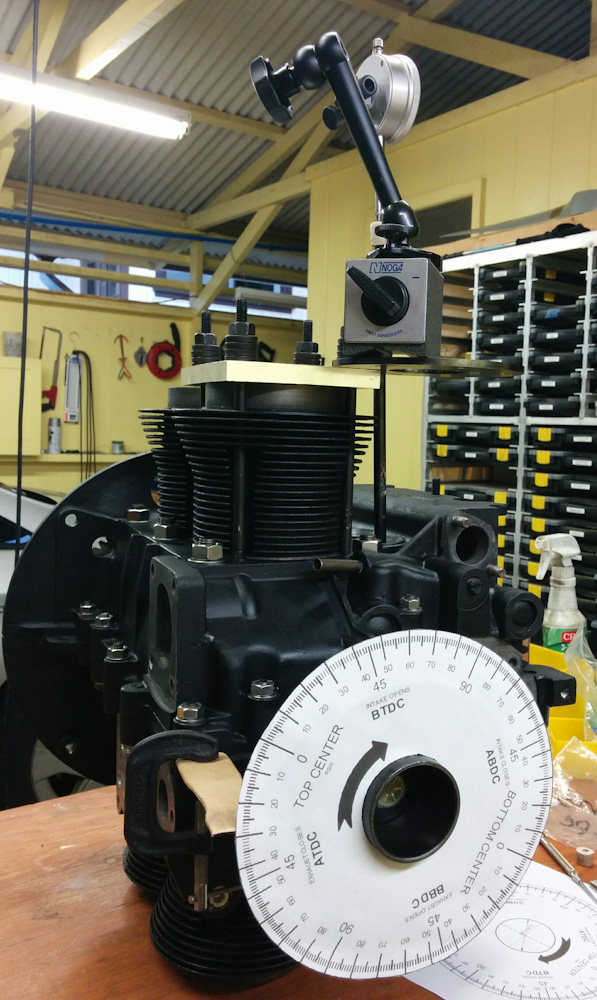
After setting deck height, it was time to set the valve geometry or, rather, the rocker arm geometry.

The entire upper valve train is getting replaced, except the valves themselves. The valve springs have started rusting, and the engine also has dual valve springs which is way overkill for the cam and RPM we are running and only serves to increase the wear and lost power due to valve train friction.

Increased spring pressure is needed if you run the engine at high RPM since the springs provide the force needed to decelerate the valve train as the valves approach max lift and begin to close. The acceleration, and hence spring force, needed here is obviously proportional to the RPM, and if the springs aren’t strong enough, the valve train will lose contact with the cam lobe. This is called “valve float” and is obviously bad since then the valves are no longer following the cam profile. However, this becomes a factor when you go over maybe 6000 RPM or have cams with very aggressive lift profiles, and our airplane engine never exceeds 4000. Single high-pressure springs should be plenty for us.

The rocker arms also have to be replaced because the threads on one of the adjusters has galled. Normally, you could just replace the adjuster, but our rocker arms are apparently some special CB Performance made for a short period a decade ago in that they have 9mm threads rather than 8mm. You can no longer get 9mm adjusters, it seems, and an entirely new rocker assembly isn’t very expensive, so I elected to replace it. The new one also has better adjusters, more on that below.

Finally, if you replace the rocker arms with a different type, you need new pushrods because their length will change. So I also have a new set of 8 pushrods that need to be cut to the correct length. Which will be determined as part of the procedure here.

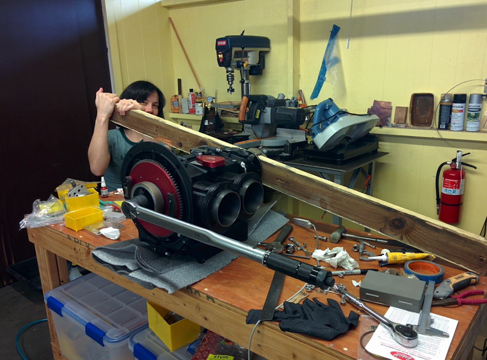
The first step is to replace the valve springs, which requires removing the valves. This requires compressing the valve springs, which in turn requires some sort of tool since these spring pressure is at least several hundred pounds. There is a dedicated tool you can buy to compress VW valve springs that makes this easy, the only problem is that it’s a large piece of metal that is prohibitively expensive to ship to Hawaii. So I decided to DIY my way through it. Once I saw how someone had done it online, it was simple: You use your drill press to push down on the spring, after having fabricated a tool that mounts in the drill chuck and fits on the valve retainer. Like this:

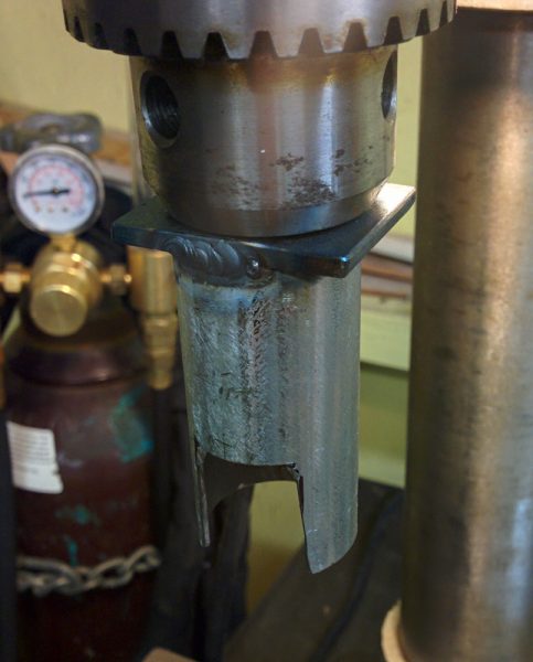
This is the DIY valve spring compressor. It’s a steel tube welded onto a steel rod so it can be mounted in a drill chuck. The tube is notched so you can get access to the valve keepers.

That took maybe half an hour to fiddle together, and it worked like a charm. In another half hour, all the springs were off. It’s amazing how having the right tool can make a job go from impossible to trivial….

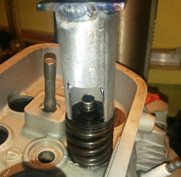
The valve spring compressor in action. It worked surprisingly well, especially given how crappy the drill press is. Note the rust spots on the valve spring. You really don’t want one of those to break, so that was reason enough to replace them.

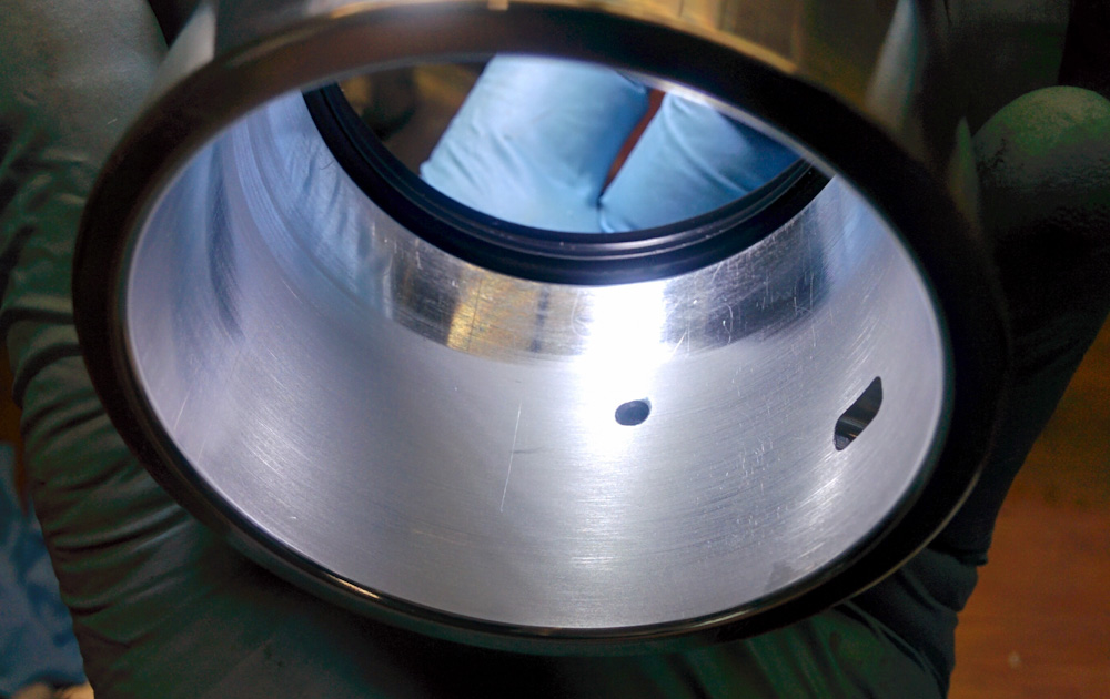
With the valves off, it quickly became apparent that the valve seats were not in a good shape. They are made out of some sort of steel, and it clearly is susceptible to rusting.

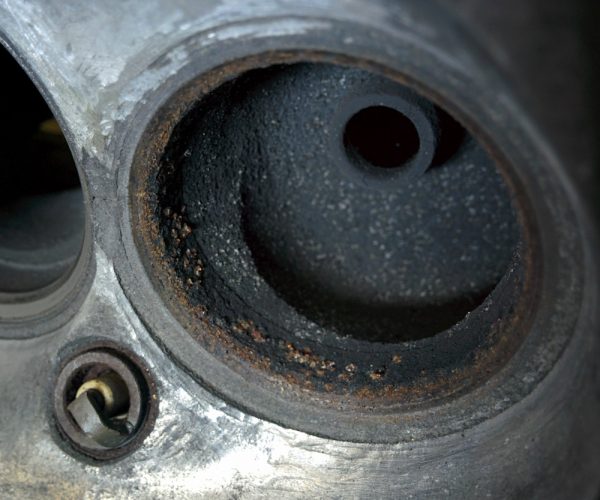
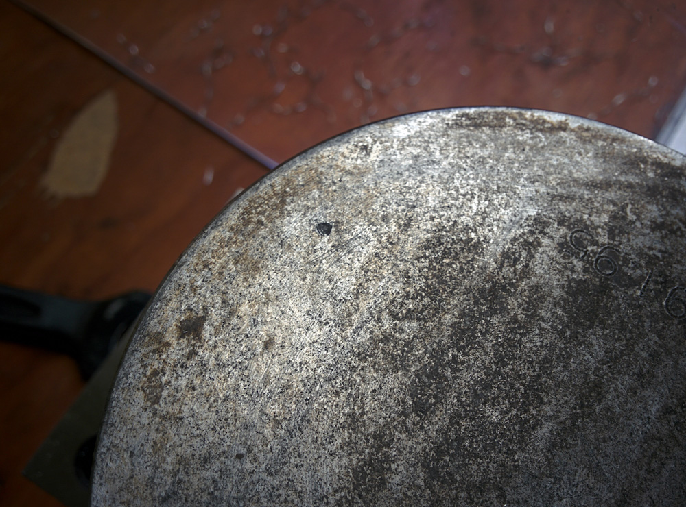
One of the exhaust valve seats after the valve came off. It’s clearly rusty and will need some freshening up.

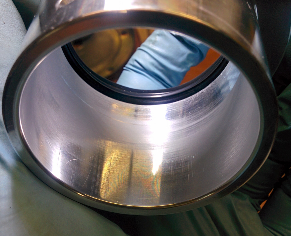
Luckily I have some valve lapping compound on hand and after lapping them for a few minutes, the seats cleaned up fine. All except one of the exhaust valves, which did not look good. I gave it back to Bear’s VW so they could re-cut the seat.

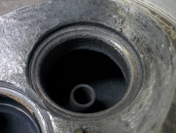
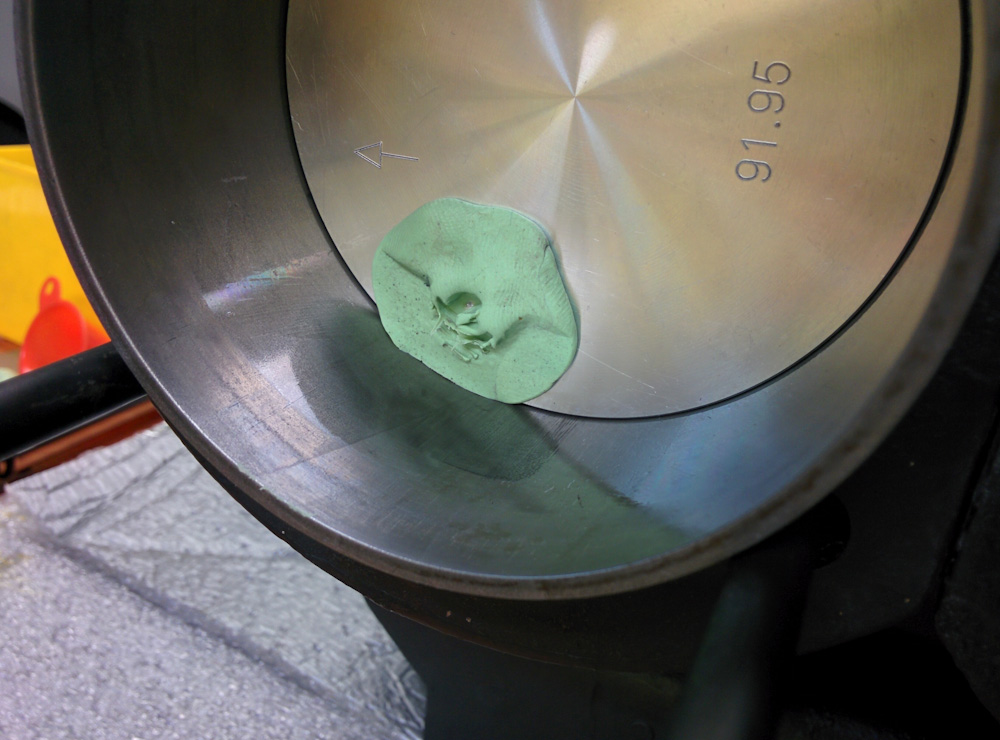
All the valve seats cleaned up nicely after some lapping except this one. There’s pitting all across the seat area, so this one went back to the VW shop to have the seat re-cut.

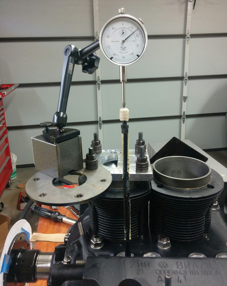
With all the valve seats reconditioned, the valves could be put back. However, it’s easier to fiddle with the rocker arm geometry if you don’t have to fight the valve springs all the time, so people recommend using some weaker springs for this. After a trip to Ace, I had the head back to looking like this.

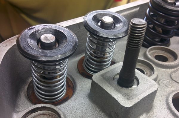
Cylinder #1 with the temporary valve springs used while working on the rocker arms. This makes it easy to push the valves in by hand and doesn’t put a huge load on the adjustable pushrod when measuring the pushrod length. The new valve springs are visible on the #3 valves to the right.

With the temporary valve springs, it’s easy to push the valves in either by hand or with the rocker arm, and the springs aren’t so strong they turn the engine, like the real ones do. Now, let’s talk rocker arm geometry. I’ve borrowed this figure from Bob Hoover’s HVX page so we have something to discuss from:

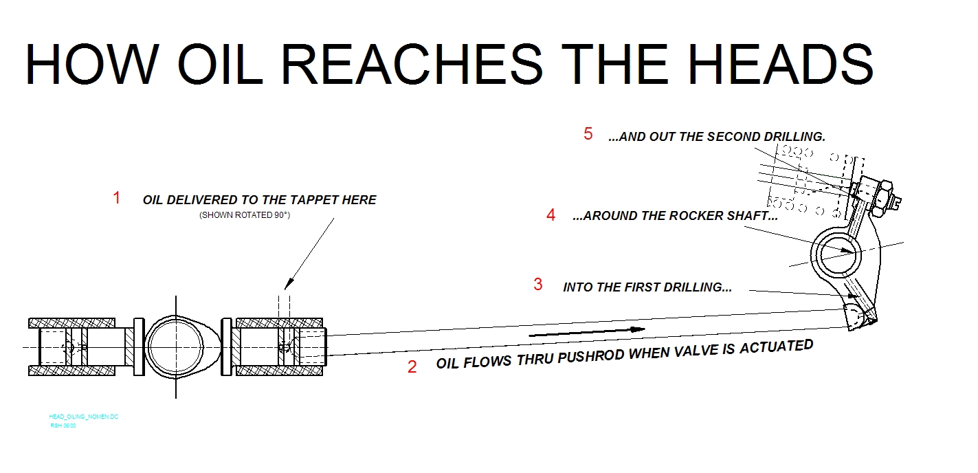
This image from Bob Hoover’s oil mods page shows the valve train components. It’s focused on oil flow but shows the layout pretty clearly. The valve stem and springs are shown faintly in the upper right. The rocker arm, which rotates around the rocker shaft (4) pushes on the valve stem, and in turn is pushed on by the pushrod (2), which is pushed on by the lifter (1) which is pushed on by the cam lobe over on the left.

There’s a lot of pushing going on here, but the basic function of the rocker arm is to reverse the pushing action of the pushrod, which is being pushed outward, away from the engine centerline, when the valve is actuated, into an inward motion of the valve stem. Because the rocker arm uses a rotating motion to generate a linear motion, it introduces a nonlinearity whenever the line between the contact points and the rocker shaft center is not perpendicular to the direction of the linear motion. Let’s expand on this further.

The pushrod end is spherical and sits in a spherical cup on the rocker arm. The inner pushrod end is pushed linearly outward by the lifter, but the rocker arm end has to move along a circle centered on the rocker arm shaft. The translation between pushrod linear motion x and the angle of the rocker arm α is x = R tan α, with suitable definitions of x and α. Since tan α ≈ α for small angles, we keep the nonlinearity small if we minimize the range of α.

On the valve end, the same thing applies. Let’s call the linear motion of the valve y and the angle of this side of the rocker arm β. We then have y = R’ tan β. We want to minimize the range of β, too. The same argument about nonlinearity applies on this side, too, but there’s another, more important reason. Unlike the pushrod, which sits in the rocker arm cup, the valve end slides against the rocker arm adjuster. The larger the value of angle β, the larger the sideways motion of the valve adjuster across the face of the valve stem. The sideways offset, which scales as cos β, should be minimized since it both wears the valve stem face and pushes the valve sideways in the guides, increasing valve guide wear.

If your eyes glazed over there, the conclusion is that to minimize nonlinearity and valve guide wear, we should minimize the range of angles traversed as the valve lifts, and that means we want to make the lines connecting the valve adjuster/pushrod cup and the rocker arm shaft center perpendicular to the valve stem/pushrod when the valve is at half lift.

The rocker arms have adjustment screws at the valve end. There are two styles of adjusters available. The old rocker arms had “elephant’s foot” adjusters, which consist of a large foot with a swivel pad.

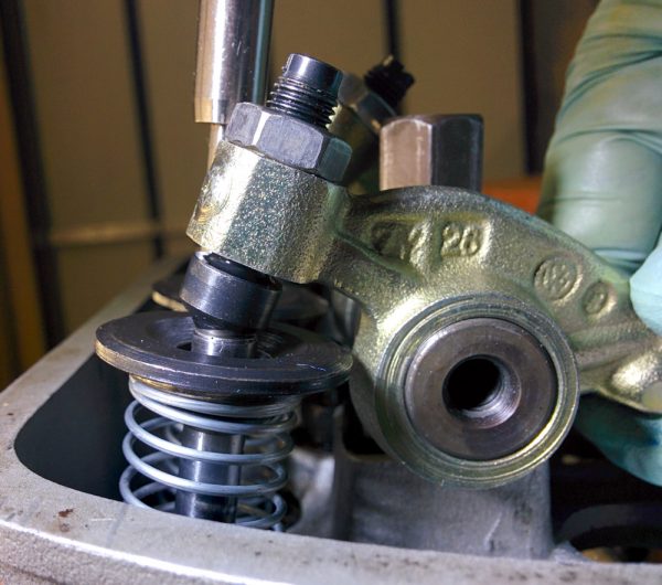
These is one of the old rocker arms, with the “elephant’s foot” style adjusters. The valve is at half lift here.

The new rockers have the other type of adjusters, the “ball” type (see pictures below). These have a steel ball which has been ground flat in one spot. The foot and ball both perform the same function, they swivel to take up the rotational motion of the rocker arm while contacting the valve stem on a large, flat area. This minimizes wear on the valve stem, in contrast to the old-style non-swivel rocker arms which have a cylindrical face that “rolls” across the valve stem as the rocker rotates. Since it’s cylindrical, it only contacts the valve along a line, so the contact forces are a lot higher.

The advantage of the “ball” type adjuster is that it has an internal oil supply. If you look at the schematic above, there’s a hole in the rocker arm connecting the rocker arm shaft to the adjuster thread, supplying the adjuster with oil. The ball adjuster in turn has a small hole in the center of its screw, so the socket in which the ball rotates is supplied with pressurized oil. The foot-type adjuster, on the other hand, does not. It relies on oil dribbling out of the adjuster threads and into the socket in the foot. Since I’ve gone through all this trouble increasing the oil supply to the heads, it seemed good to ensure the adjuster is well-supplied with oil. Having the oil spray out of the adjuster also serves to splash oil across the top of the head where it can absorb some of the heat from the exhaust port, although that may or may not be a noticeable effect.

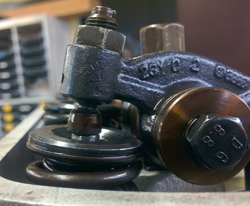
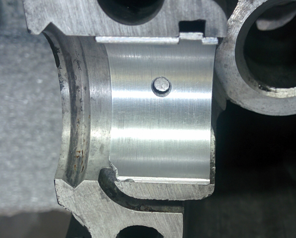
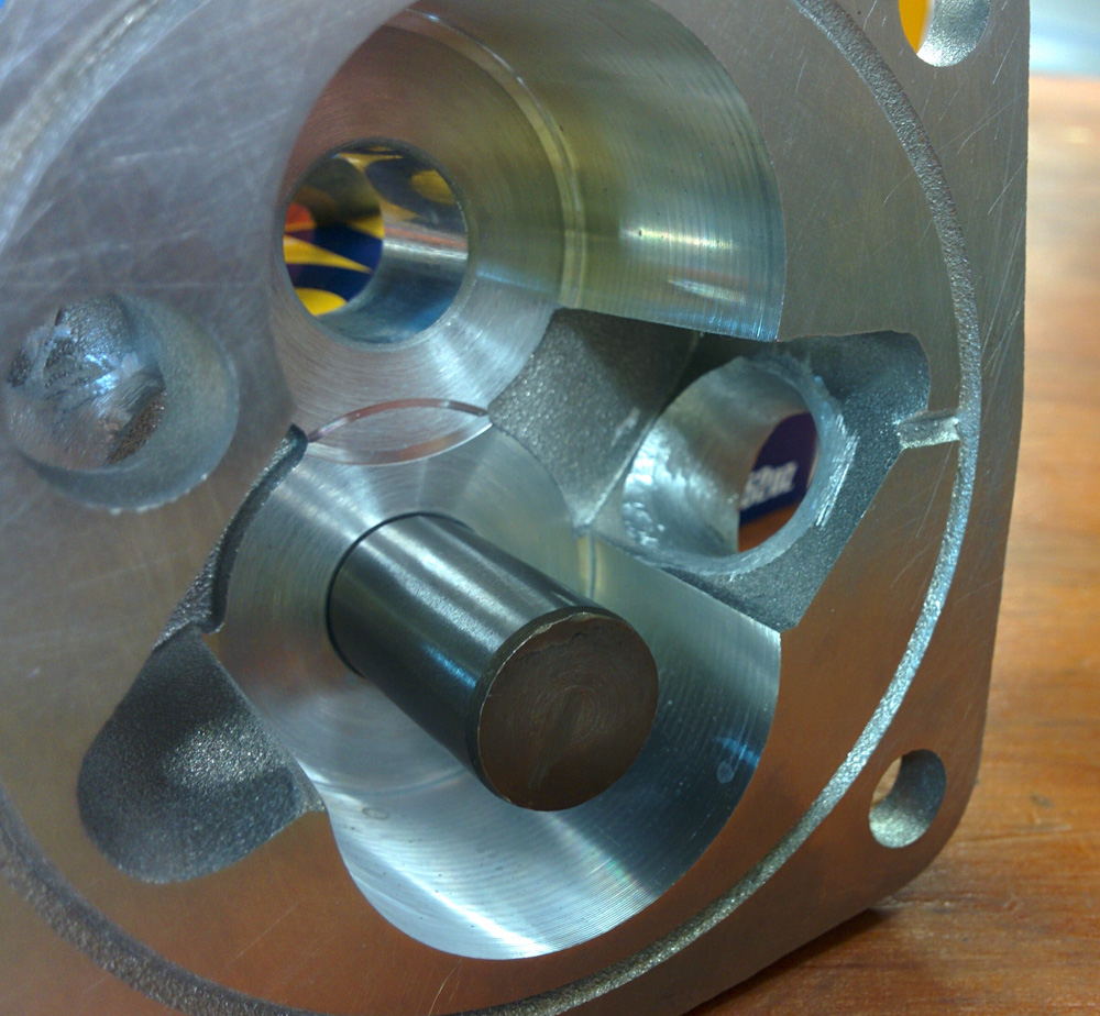
The new rocker arm at zero lift. Note the ball-style adjuster.

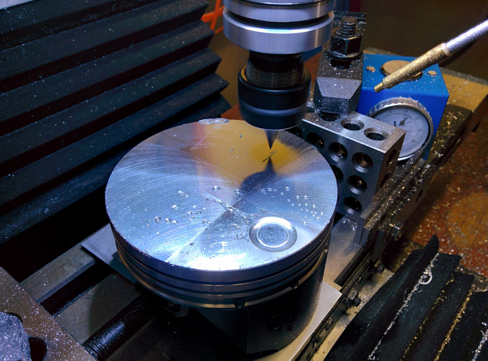
In order to get as good a geometry as possible, it’s necessary to modify the rocker arms somewhat. It turns out the adjuster pokes out too far, so unless the rocker is modified, the pushrod will need to be cut too short. The solution is to cut about 1.5mm off the valve-side of the adjuster thread on the rocker arms. I did this on the mill, but the rocker arms must be made of some quite hard material because after cutting a few of them it started throwing glowing chips around. This is usually a sign that either the end mill is spinning too fast or, more likely, the end mill had dulled to the point that the cutting forces were putting enough heat into the material to make it glow. This was a bit disconcerting, and the quality of the cut had degraded noticeably by the time I got to the last rocker arm, but it worked very well.

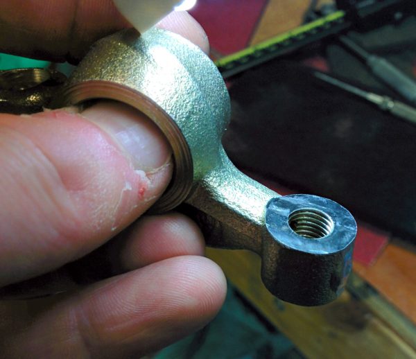
One of the rocker arms after cutting 1.5mm off the valve side of the adjuster thread on the mill. This makes it possible to put the rocker at a more optimal angle.

Before mounting the rocker arms for the final time, another small modification was called for. As part of the “HVX” oil mods to increase oil supply to the rocker arms, it is recommended to connect the incoming oil supply hole from the pushrod to the hole going to the adjuster by cutting a small groove in the inside surface of the rocker arm where it rotates on the shaft.

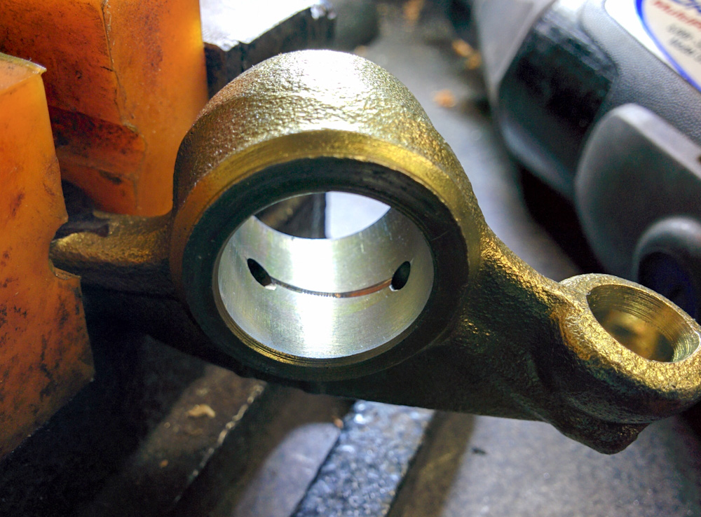
The groove cut in the rocker arm to enable oil coming in through the hole from the pushrod to pass directly through to the adjuster.

Without this groove, the only oil that will make it into the adjuster hole is whatever happens to ooze around the rocker shaft. The rocker shaft has a circumferential groove cut into it, but the two holes in the rocker arm are offset laterally so there is no way for oil to make it from one hole to the other through that groove. Since this involves using the Dremel cutting disk inside a fairly small hole, I practiced on four of the old rocker arms first to make sure that I could do it without having the Dremel go out of control and damaging the bearing surface.

With the grooves cut, it was finally time to start fitting the rocker assembly. From the analysis above, there are two angles that need to be controlled, the angle between the valve stem and the valve-side of the rocker arm (α above), and the angle between the pushrod and the pushrod side of the rocker arm (β).

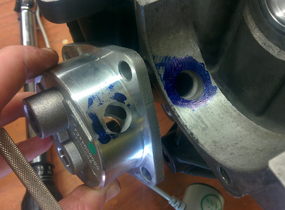
The first angle, α, only depends on the position of the rocker shaft and is independent of the shape of the rocker arm, so it is set first. The rocker shaft can be moved by adding shims between the rocker assembly and the head. More shims moves the rocker shaft outward. We are looking for the position when the surface of the valve stem, at half lift, intersects the rocker shaft.

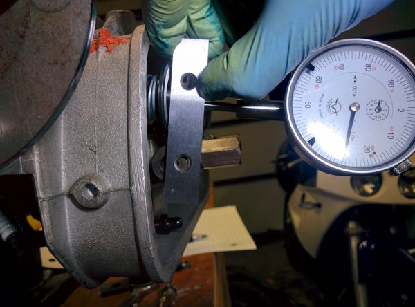
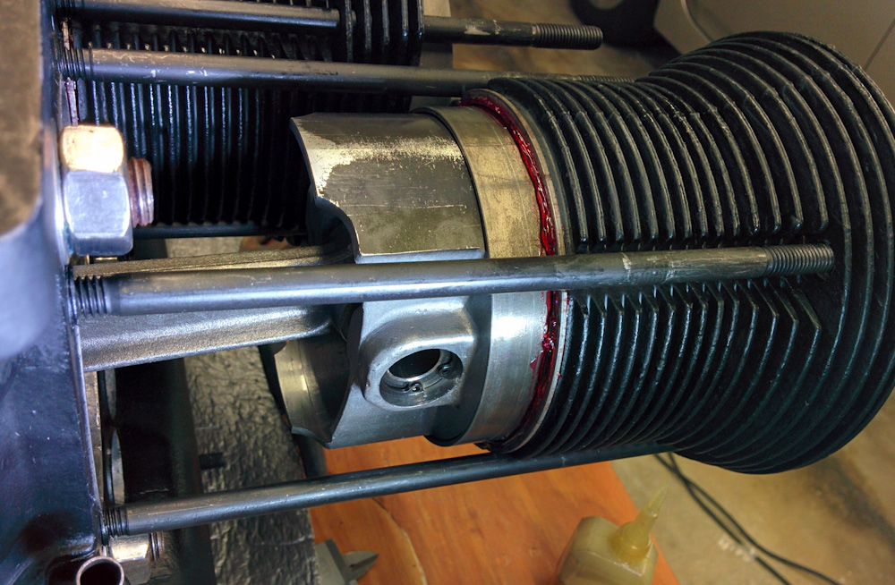
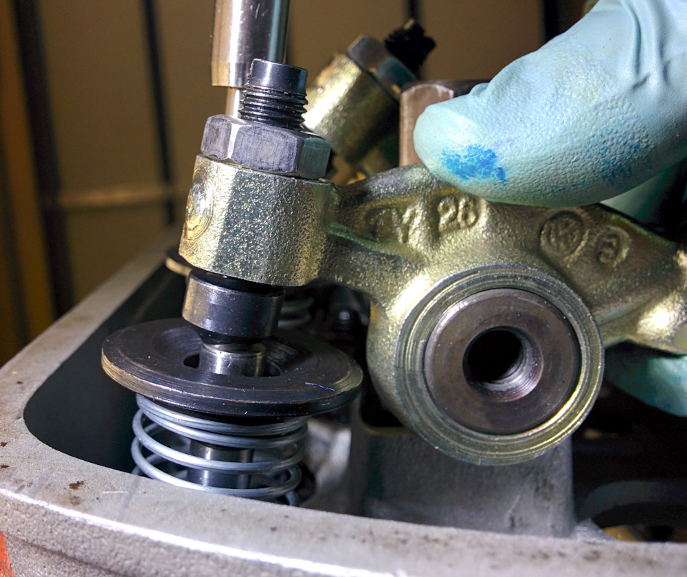
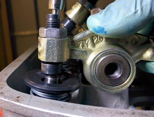
With the valve at half lift, the plane of the valve stem end, indicated here with the parallel I’m holding against it, should pass a distance away from the rocker shaft that is equal to the radius of the ball on the adjuster.

Actually, that is not quite true. I was confused about this for a while, but the place where rotating motion is converted to linear motion is the adjuster ball, not the valve end. Hence, it should actually be the line from the center of the adjuster ball to the rocker shaft that should be perpendicular to the valve stem. The ball center sits about 2.5mm above the end of the valve stem, so this means that the line of the valve stem end should intersect the rocker shaft center when the valve is at half lift – 2.5mm. With the dial indicator mounted against the valve retainer, this point is easy to find, and you can fairly accurately judge when the straight edge of the parallel in the picture above cuts the rocker shaft in half.

The sanity check is to then verify that the ball moves laterally across the valve stem face such that it’s in the same place at zero and full lift. (It’s not super easy to see this because the adjuster itself rotates and confuses the eye, but it served as a good enough sanity check that it alerted me to the fact that I had not taken the ball radius into account when I tried this first. This resulted in too few shims and a very clear tendency for the ball to slide across the stem more near zero lift compared to full lift.)

We can now compare the geometry at zero, half, and full lift:

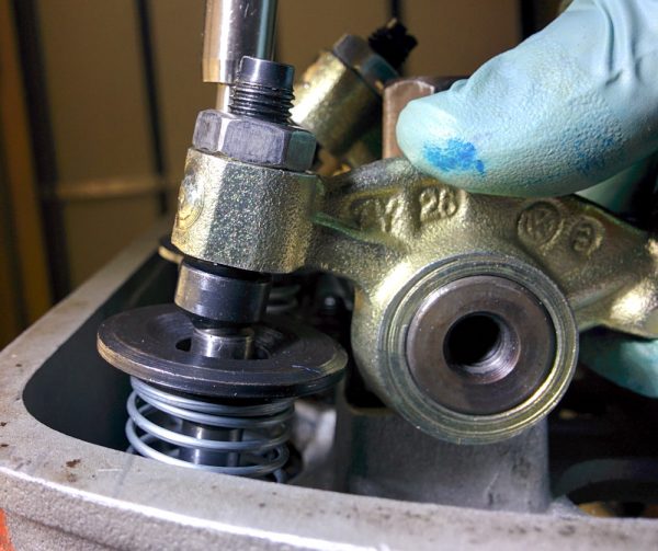
Same picture as above, with the rocker arm at zero lift.

Rocker at half lift. The line from the center of the adjuster ball through the rocker shaft should is close to perpendicular to the valve stem, although it’s hard to see in the picture. The ball is also maximally outward on the valve stem in this position, compared to the pictures at zero and full lift.

Rocker at full lift. Note that the lateral position of the ball on the valve stem is now very close to the same as at zero lift.

With the valve side of the geometry now fixed, we need to worry about the pushrod side. The pushrod side of the rocker (at half lift) can now be moved by screwing the adjuster in or out. We are looking for the place where the line through the center of the spherical end of the pushrod to the rocker shaft is perpendicular to the pushrod itself. I did not manage to take a picture of this, you need more than two hands to hold everything in place, but it turns out that there’s not much to do here. Even with the 1.5mm taken off the adjuster side, and the adjusters screwed as far into the rocker arms as possible, you can still not get the rocker arm to rotate far enough to get the other side into a perpendicular angle. This makes it easy, we just have to keep the adjuster as far into the rocker as possible (while retaining some adjustment range) and then cut the pushrod to a length that gives us the desired 0.006″ valve clearance.

In practice, the valve stem ends aren’t coplanar, though. The exhaust valve seats have apparently been recut more than the intake ones, because both exhaust valves poke out more than the intake valves. This means we can’t get the geometry correct for all valves, so we have to pick one. It turns out that the #1 exhaust valve that I’m using in the pictures above is approximately in the midway of the range, so that’ll work.

Since the valve stems aren’t coplanar, this also means that if we cut all pushrods the same length, we’ll have to take up the slop in the adjustment screws. I think it would be ideal to have every adjuster as retracted as possible, in order to get the pushrod end geometry as good as it could be. However, it would be a lot of work to measure and cut individual pushrod lengths for every valve (not to mention the possibility of getting them mixed up) so I’m going to accept this suboptimality.

The final adjustment that has to be done is to set the side clearance of the rocker arms on the shaft. There needs to be some free play here so the rocker arm can move freely and the oil can make it out from between the shaft and rocker arm. Too much free play, however, will make the rocker arm clack sideways when pushed by the pushrod, since the pushrods aren’t perfectly perpendicular to the rocker shaft and imparts some side load on the rocker arms. The old rocker shaft had gigantic free play, which makes for a noisy valve train and increased wear from all the sideways motion. The recommended clearance is 0.005″ (0.125mm) per rocker arm (the two center arms can move together, so they need extra play) which can be adjusted by adding shims on the rocker shaft. At the same time, these shims set the sideways position of the rocker arm on the valve stem. You want the rocker to sit somewhat off-center on the stem, since this makes the valve rotate slightly and makes it wear more evenly. There’s nothing particularly tricky about this, but you have to fiddle with the shims back and forth until you get both the correct play and the correct positions.

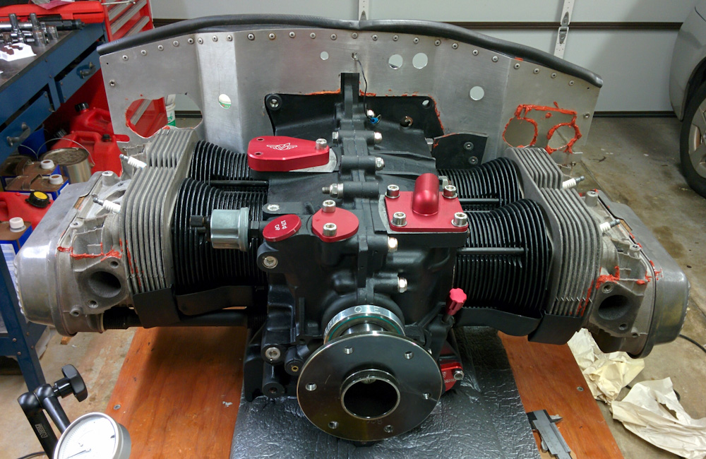
With the rocker geometry set and pushrods cut, we’re at final assembly. It is time to put the piston rings on, seal the cylinder barrels, and mount the heads for hopefully the final time.


Engine guts 12: Setting deck height

(In case anyone wondered why there was a lapse in updates, it’s because of this little guy who arrived on January 28. It’s gotten a bit harder to find time to work on the engine since then, although it’s so close to the end I’m going to try hard to get it done.)

Axel, the source of engine work delays…

Now that the case is closed, the next step is to set the deck heights. On a VW, the cylinder barrels are separate from the crankcase, and the combination of crankshaft stroke, connecting rod length, piston height, and compression ratio affects how close to the top of the cylinders the pistons come at top dead center. This is called the “deck height”, and must be set correctly since it affects the compression ratio of the cylinders.

The deck height can be adjusted in two ways. First, by adding shims under the base of the cylinder barrel. More shims here puts the cylinder further out from the case and hence increases the space between the top of the piston and the top of the barrel. Second, if the desired change is small, the pistons themselves can have their top surfaces fly-cut down a bit. You obviously don’t want to take away a lot of material this way, but since shims with thicknesses less than a millimeter aren’t common this is a way to get exactly the height you need.

There is another reason you might want to fly-cut the pistons rather than add shims: You can set each cylinder’s deck height individually this way. Since the heads go over both barrels on each side, the two cylinders need to have the same shims or their top surfaces, which seal against the head, won’t be co-planar. Now, ideally, the combustion chambers will have exactly the same volume and hence you want exactly the same deck heights, but in the real world that’s not the case. On our engine, the combustion chamber volumes are the same to within a cc. To get the same compression ratio on the different cylinders, this translates to a different deck height of about 0.1mm. Not much, but if you’re going to fly-cut them anyway, you might as well do it right.

There is another consideration with deck height: you don’t want it to too large. The combustion chamber only takes up a part of the cylinder cross-sectional area (see the pictures of the heads in the linked post above.) The rest, known as the “squish” or “quench” area, becomes very thin when the piston is at the top. If the piston came up exactly to the top of the cylinder, there would be no volume here at all and all the fuel/air mixture would be squished out (hence the name.) This is desirable for several reasons. First, it concentrates all the fuel/air mixture closer to the spark plugs and hence helps it burn more quickly. Having combustible mixture hang out far away from the spark plugs increases the risk of it spontaneously igniting before the flame front has time to reach it, so that makes the cylinder more detonation-prone, which is a bad thing. Second, as the mixture is squished out from the quench area into the combustion chamber, it creates turbulence which helps the combustion process. For all these reasons, you want to keep the deck height small, ideally no more than 2mm between the piston and the deck surface in the head.

All this means you really want a zero deck height. However, for practical reasons that’s not possible. You really don’t want the piston to hit the head and some clearance is needed to allow for thermal expansion, bearing wear, and the fact that the piston can cock itself slightly in the bore. For these reasons, people don’t recommend setting a deck height less than 1mm in the VW. So for an efficient, reliable engine, you’re constrained from both ends here.

With our engine, there is another concern. As shown in the combustion chamber post earlier, the spark plugs for the secondary ignition protrude above the deck surface in the head, with significant variation between the cylinders. When I test-fit the heads and turned the engine over, I could feel a slight interference when piston #4 reached top dead center. After removing the heads, a slight mark on the piston surface was apparent, corresponding to the location of the spark plug. Apparently the piston came too close to the head in this cylinder (which is the one where the secondary spark plug protruded the highest.)

The mark in the center of the picture coincides with the location of the secondary spark plug in cylinder #4. Of all secondary spark plugs, this one protrudes the highest above the head. Apparently, the deck height used previously was too small, letting the piston hit the spark plug.

This wasn’t the correct deck height, I was just using a 1mm shim on all cylinders as a baseline, so it wasn’t an immediate concern. I was surprised, though, because by my estimation there should be clearance to all the spark plugs. Intrigued, I dug out the old #4 piston and, voila, there’s a clear impact mark in the same location! Apparently there has been insufficient clearance here all along.

By sticking some clay on the piston, mounting the head, and turning the engine over, we get an imprint of how close various parts of the head gets. This picture confirms that the electrode for the spark plug has pushed all the clay out of the way and is contacting the piston. It also shows that the edge of the spark plug, which comes in at a shallow angle, also is very close to the piston.

I double-checked this by doing the classic “clay test”. By affixing a piece of clay to the piston tops and turning the engine over, you get an imprint of the head shape. By doing this on the four cylinders, the interference on the #4 piston was confirmed. It also showed that the spark plugs on the other cylinders were dangerously close, certainly violating the desired 1mm clearance.

This presented a dilemma: The 1mm desired clearance obviously applies to the highest point in the head. This normally is the head deck surface, but in our engine it’s the secondary spark plugs. If the deck height is set to clear the spark plug by 1mm, the result would be a too wide squish clearance, maybe 2.5mm, and too low compression ratio.

Since this engine will run 100 octane avgas, there should be plenty of margin to set a compression ratio a bit higher than the 8.0:1 recommended by Sonex for 93 octane and up. Based on what people have run in other aircraft VW conversions using 100LL, I decided to target 9.0:1, which results in a squish clearance of about 1.6mm. This is also more in line with what people recommend for our class of camshaft.

Given that we will also be using a 1.0mm copper head gasket, which adds to the combustion chamber volume, the desired deck heights come out as follows: (The measured chamber volumes include a 1.6mm head gasket, so the 0.6mm difference needs to be taken into account if anyone wants to do these numbers themselves.)

  • Cylinder 1: Combustion chamber 66.4cc, desired deck height 0.70mm, measured 0.33mm, remove 0.37mm from piston top.
  • Cylinder 2: CC 66.9cc, desired deck height 0.62mm, measured 0.20mm, remove 0.42mm.
  • Cylinder 3: CC 66.9cc, desired deck height 0.62mm, measured 0.32mm, remove 0.30mm.
  • Cylinder 4: CC 67.3cc, desired deck height 0.56mm, measured 0.14mm, remove 0.42mm.

The obvious solution to the clearance problem is to make a little depression in the pistons. It only has to be 0.8mm deep to give us the desired clearance. The big question obviously is: would removing 0.8mm material (in addition to the fly-cutting, which will remove up to 0.4mm depending on the cylinder) weaken the piston too much. There’s no easy way to answer this, but asking a few VW people their guess was that it would be OK. The area is close to the edge of the piston, and the piston crown gets progressively thicker the closer to the edge you get. The stresses also go down closer to the edge. It appears the piston is about 7mm thick in this area, so 0.8mm is not negligible but it’s only over a 15mm wide area. We’re also not pushing these pistons that hard, so there should be some margin.

Having decided on this course of action, I programmed the operation up in Fusion 360, figured out how to mount the pistons on the mill, and, after test-cutting on the old pistons a bunch of times, went ahead and modified them.

Modifying the new pistons on the mill. After fly-cutting the tops down the appropriate amount, a shallow depression was cut to improve clearance to the secondary spark plug.

Much more time was spent deciding on a course of action, doing the CAD/CAM, and testing than the actual cutting time. The job only took about 10 minutes per piston, and half of that was in tool change time. I made a movie of the entire job in case you want to vicariously follow along:

So that’s one more thing to check off the list. We should now have correct deck heights and compression ratios, without any risk of interference. In principle it’s now possible to bolt the cylinders and heads on, but I’ll hold off just a bit on doing that because first I want to verify rocker arm geometry and it’s nice to be able to test-fit the heads for that purpose. But it’s getting close!


Engine guts 11: Closing the case

It’s finally time to close up the case. But first a little tidying up.

There’s been a small amount of binding when turning the crankshaft with the Force One bearing mounted. Over perhaps 120 degrees, it was harder to turn than seemed normal. I had measured earlier that the prop hub had a runout of about 0.002″/0.05mm. If the bearing was mounted slightly off-center, it would rub against the journal when the two pointed against each other.

I spoke to Great Plains, who said that most of the time when there is binding in the bearing, it’s because the hole dowel pin that hold the bearing in place isn’t drilled deep enough and it’s squeezing the bearing. I verified that was not the case since removing the dowel pin completely didn’t change things. I also determined that it was not the bearing that was uneven, since rotating the bearing in the case did not rotate the point at which the crankshaft was binding. The only conclusion was that the shop that bored the case to mount the bearing did not get it perfectly centered.

Since the effect must be very small, I decided to try an experiment. I added some lapping compound (30 micron) to the bearing (which is aluminum), bolted everything together, and turned the crankshaft for a few minutes. This got rid of the binding. After taking everything apart and cleaning up the bearing, it was clear that some material had been taken off at a section. I continued with 12 and 5 micron compound to smooth the surface out. After this exercise, the bearing now spins without any noticeable binding.

This is the side of the Force One bearing that was abraded the most by the lapping compound, as evidenced by the matte area.

The other side of the bearing. This one still got cut a little bit, but is mostly untouched. By the pattern it looks like the bearing is actually mounted slightly cocked in the case.

Unfortunately I don’t have the equipment to measure the clearance between the bearing and the journal. It would be good to know whether this operation cut too much material so the bearing now has too much clearance. The guys at Great Plains couldn’t give me a number on what the expected clearance is, though.

Another little thing that had to be done was to notch the cam bearing by the flywheel for the oil return passage. Another example of the half-assed fit of these parts.

The cam bearing on the flywheel end of the case was a tad bit too wide and partially blocked the oil return passage, so it had to be ground back a bit.

Finally, it was time to close everything up. For sealing the case halves, people highly recommended Hylomar, a non-setting gasketing compound that supposedly works very well in situations where it’s important that there be absolutely no buildup, like the case halves that are already a very close fit. It’s a translucent blue, very thin, material that smears out to practically nothing. I applied it all over one of the halves.

Hylomar sealant applied, in a very thin layer, to the case halves without studs, where it’s easier to get it around all the bolt holes.

Checking once again that everything was ready: all the bearings seated correctly, all 8 lifters greased and in place, cam plug in place, cam gear meshed correctly, rubber seals in place on all 8 main bearing studs, cam gear bolts torqued and loctited. I attempted to get the case halves to mate. I’ve done this for fitting purposes probably 25 times by now and never had a problem, but the one time I’d applied sealant would of course be the time where they did not go together properly.

Everything’s ready to go together.

Taking them apart again, I noted a cam bearing had slipped out of place slightly. Luckily the case flange surfaces never actually mated so the sealant was undisturbed, and the second time everything went together OK.

To avoid oil leaks, I also applied Hylomar to the washers for the main bearing studs and cam studs, and then on the underside of the nuts. This was a bit messy even though I attempted to put on as little as possible. The M12 main bearing stud nuts were secured with Loctite red. (They originally had Nylon locknuts on them but I was unable to find M12 fine thread lock nuts in stainless, and given how corroded the original nuts were I didn’t want to put back steel nuts.)

Gradually going around and tightening the big studs and then all the ones around the circumference of the case, you could tell that the Hylomar was gradually getting squeezed out from between the case halves as you came back a few minutes after tightening them and they would then tighten a bit more. I really hope we don’t get any oil leaks here.

The case halves are finally bolted together again.

Once the halves were together, the next step was to mount the main seal and flywheel. The first thing I did was to double-check the crankshaft axial play which, if you remember, was what started this whole ordeal back in October.

Checking crankshaft end play. With the test indicator mounted on the flywheel, pushing the crank back and forth shows the endplay directly. It’s a bit out of focus, but the test indicator was zeroed at 40 and read 30, so the play is 0.10mm/0.004″. The spec is 0.07 – 0.15mm, so we’re right in the middle.

To test this you have to add the shims to the crankshaft and then mount the flywheel. The nut on the flywheel is supposed to be tightened to 250 lb-ft, a crazy amount of torque, but for testing purposes I figured it was good enough to just tighten it real good. It came out to 0.10mm, just like when I had gotten the shims weeks ago. All good there.

Before you mount the flywheel, though, the main seal needs to be pressed in place. It’s about 90mm is diameter, so I was looking for something that would fit over the seal with a suitable hole in the center, so I could use the flywheel nut to pull the seal into position. (I have not had good experience using any kind of tapping on these seals, they always end up leaking.) Turns out the crush plate that came with the Force One hub worked quite well.

The improvised seal pulling tool, the Force One prop plate being pulled in with the gigantic flywheel nut and washer.

I had applied Hylomar to the perimeter of the seal, thinking this would help avoid leaks there. Alas, this was not a good idea. After pressing the seal in place I watched it slowly creep back out until it popped off. Clearly something with more friction was called for here. I had read somewhere that Loctite retaining compound was a good choice, so I decided to try that instead.

Amazingly, the thin layer of Hylomar reduced the friction between the seal and the case enough that it slowly creeped back out.

Cleaning off the Hylomar was not that easy, it’s pretty solvent-resistant. After trying acetone and ethanol without much luck, I finally pulled out the Xylene. That did the trick.

Repeating the operation, now with the retaining compound rather than the Hylomar, everything went smoothly and the seal stayed in place.

After using Loctite retaining compound instead, the seal stayed in place.

Finally, the flywheel could go on. To avoid oil leaks through the dowel pins, I applied Hylomar to the gasket that goes between the crankshaft and the flywheel. The Aerovee instructions call for silicone RTV here, but others discourage that because it builds up too thick and leads to excessive axial play.

The flywheel gasket got a thin coat of Hylomar on both sides, making sure to go on both sides of all the dowel pins.

It was finally time to tighten the gland nut. To be able to hold the crankshaft in position, I had drilled holes in a piece of wood that I bolted to the prop hub. Getting help from Kathy, who held that end of the engine down, I pulled on my largest torque wrench until the piece of wood cracked.

Digging out a long 2×4 from under the house, I quickly (the Loctite on the nut was setting up) drilled a 2″ hole in the center so I could squeeze it between the prop hub and crush plate. With 3 feet on either side, there was plenty of lever arm for Kathy to hold the engine down while resting the other end on the bench so it wouldn’t turn. I basically put all my weight on the 250 ft-lb torque wrench before we got it to click. What an ordeal.

My human counterweight holding the prop end of the crankshaft while I tighten the nut with the big-ass torque wrench to 250 ft-lb.

So there we go. The case is together. Now we can proceed to pistons, cylinders, and the heads. The next operation will be to set the deck heights.


Engine guts 10: Blueprinting the oil pump

After dialing in the cam, I moved on to the final (I hope) grinding work that needed to be done before the case could be closed up: blueprinting the oil pump.

I had to get a new oil pump because the old one had the external connections for the oil cooler, which we will no longer use with the new filter setup we designed. There are a few small modifications that can be made to the oil pumps to increase their efficiency. (These are not new, they’re outlined in the book “Hot to hotrod VW engines” from 1970. Apparently the design of VW oil pumps have stayed the same for the last 50 years…)

The first step is to verify that the inlets and outlets of the pump actually line up with the corresponding passages in the case. VW Type 1 oil pumps are cylindrical and pressed into the front of the case. (The suction passage from the sump and the outlet going to the oil galleries are holes in the cylindrical surface.)

The first step of blueprinting the pump was to literally mark the passages in the case with dye and verify that they lined up with the passage in the pump. The inlet was pretty good, the outlet was not. Note how the blue-free region extends above and to the left of the hole in the pump.

As you can see in the picture above, the outlet in the pump was significantly offset from the case. This was corrected by upsizing the hole in the pump with the Dremel. There was probably also a corresponding place where the case should be opened up to match, but I was not willing to go that far — I’ve already cleaned the case out from swarf and plugged the passages up.

The next thing to do is to smooth the inlets and outlets on the inside of the pump. This is especially important on the inlet side, since pumps are sensitive to flow restrictions there. If there is too much pressure drop, the oil pump can even cavitate, which really ruins your oil pressure. The oil pump is a traditional gear pump, where the oil is transported in between the teeth of the gears. The inlet in the VW pump is mostly aimed at the driven gear, which makes it harder for the flow to go to the idler gear. The solution is to radius the inlet and open it up as much as possible towards both gears.

The pump inlet opening has been radiused to open more gradually, especially towards the front of the pump (although that’s hard to see in the picture) and towards the bottom gear. I could probably have been even more aggressive here, but this is a lot better than the sharp edges of the stock inlet.

The pump outlet shape isn’t as critical since this is a high-pressure area, but it has also been smoothed to avoid sharp edges. The pump also has this vertical outlet hole facing the front of the pump. This is used for attaching full-flow filter fittings, but has no function here. I did my best to round out those edges, too.

The final thing to check is the clearance between the pump gears and the lid at the front of the pump. Excessive clearance here gives the oil a path to leak back from the outlet to the inlet side and lowers the efficiency of the pump. This is especially noticeable when the oil is hot and less viscous. You want as little clearance as possible when cold here, since the aluminum pump body will expand more than the steel gears as the pump heats up. This clearance can be shrunk (but not increased) by carefully sanding the pump body down with sand paper against a flat plate.

The stock pump had about 0.20mm clearance, and the spec is <0.10mm. After some judicious sanding, I was down to between 0.04-0.05mm, as measured with a feeler gauge between the gears and the lid. That should be good.

This is the oil pump being mounted in the case, a small jump forward in time to after the case halves had been mated. (That will be in the next post.) The pump gears are coated with white lithium grease to help the pump “prime” when first started. Since there’s no oil there, the pump may not be able to suck the oil up from the sump without the sealing aid of the grease. The thin, blue coating on the lid surface is the “Hylomar” sealant.

The pump is tapped into the case after the case halves have been mated (which has happened and will be in the next post, when I get a chance to write it up.) The gears are coated with grease and mounted (the driven gear extends through the pump to the cam shaft, where it hooks into a slot) and finally a thin layer of sealant is smeared on the outer perimeter of the pump and the lid mounted. That’s all now done, so one more thing to check off the list.

Next will be actually closing up the case halves.


Engine guts 9: Dialing the cam

One of the few remaining things to check was to “dial the cam”, i.e., to verify that the camshaft and crankshaft are timed correctly. In its most basic form, this is done by ensuring that the marked teeth on the gears on the crank and cam shafts are aligned, and if you were assembling a stock VW made by the factory, that might be the end of it. However, VW’s these days are collections of aftermarket parts and stackup of tolerances can lead to significant discrepancies between the actual valve timing and the design. The only way to be sure is to actually measure the lifter motion and see if it agrees with what it’s supposed to be.

This is a somewhat involved operation because you have to assemble the engine with lifters, camshaft, connecting rod, and pistons. (Technically you only need the #1 piston and lifters since if it’s right on one cylinder it’s going to be right on the others, too.) A way of reading crankshaft position is needed, so you mount a degree wheel on the crankshaft. Then you need to find the top dead center (TDC) of the piston with a dial indicator and align the degree wheel so it reads crank degrees.

Once you’re at this point, you can hook a dial indicator to the lifters and measure where the valves open and close and compare to when they are supposed to according to the cam data sheet. Bob Hoover’s blog has a pretty detailed description of this whole process, with much more detail than I’ll go into here, in case you are interested.

The engine set up for verifying the cam timing. The degree wheel attached to the prop hub indicates the crankshaft angle, in this case 28 degrees ATDC (After Tod Dead Center). The dial indicator is showing the position of the lifter, see the next picture.

The cam in our engine is an Eagle Performance 2234, and I found the card specifying valve open/close times in the Sonex files. However, it was kind of hard to read the writing on the card, and it did not actually specify at what lift open/close was defined at. Since the valve isn’t really either open or closed, it’s just lifted some specific amount, you need to define the amount of lift you are referencing the opening/closing to. A quick email to CB Performance gave me the answer: They use 0.015″ lift, and the spec is: “Intake Opens 33 – Intake Closes 61 – Exhaust Opens 67 – Exhaust Closes 27”. (Those all have implicit BTDC/ATDC, etc, depending on the event. See the Hoover article for the details.)

Now I knew what lift I was looking for. However, hooking up the dial indicator to the lifter turned out to be a bit complicated. The lifters are way down inside the case and the dial indicator can’t reach them. I first tried to just stack a socket on top of the lifter, which kind of worked but was very unstable. I needed something that could sit in the lifter cup and have another cup on the opposite end that the dial indicator could sit in. A pushrod is the obvious thing that can sit in the lifter, since that’s what it’s made for, but the other end is convex. After rummaging through the engine boxes I found an adjustable pushrod, and I realized I just had to make a little head for the top of it where the dial indicator could sit. Enter the JB Weld.

The adjustable pushrod and the chink of JB Weld that goes over it, with a small divot on the end that the dial indicator can sit in.

That worked like a charm, now I had very stable readings.

The dial indicator attached to the top of the pushrod, which in turn is sitting in the exhaust valve lifter. It’s indicating 0.015″ lift. This is the exhaust closing point. The crankshaft angle is the same as in the first picture, 28 degrees ATDC. Since the cam spec is for exhaust close to be at 27 degrees ATDC, we are within a degree.

The first measurements were intake: 35/58, exhaust: 76/24. Compared to the spec 33/61, 67/27, this indicates that the events happen 2-3 degrees early relative to their specified position. (Because the openings are “angle before” and closings are “angle after“, a larger value on the openings and a smaller value on the closings corresponds to “earlier” in the camshaft rotation.) The only exception was the exhaust opening which is off by 11 degrees. I don’t know what’s going on there, but the other three points are pretty much in agreement. 3 degrees is a pretty large error, if you manage to get a tooth off when meshing the cam gear, I think you get an offset of 6 degrees, so this was half of a tooth.

To correct this, you have to rotate the camshaft relative to its gear. There are various fancy ways of doing this but the one requiring no special parts is to simply file the bolt holes in the cam gear a bit larger. This allows you to rotate the cam a bit when bolting it to the gear, and as long as you don’t make the holes large enough to compromise the seat the bolt is bearing on, it’s fine. In this case I had to elongate the holes just under 1 mm, which I did by wrapping sand paper around a drill bit of suitable diameter and filing them out. It took a while but worked pretty well.

When I bolted the whole thing back together and re-measured, I was pleased to note that the timing was now intake: 61.5/33, exhaust 72/28, within a degree of the spec (except for the exhaust again…) Since it’s hard to reliably read anything less than a half-degree increment from the printed degree wheel, and a degree is not going to have a major impact on performance, I called that good. As for the exhaust, I don’t know. Maybe I’ll measure the other cylinders to see if the lobe on the cam is just funny.

There are now only a few more things that need to get done before the case can be closed, and then we have a bit more work to do with deck heights and rocker arm geometry. I’m seeing the light at the end of the tunnel!


Engine guts 8: Balancing act complete

The balancing of the new connecting rods and the pistons is now done. They were within about 1.5 grams to begin with, so there wasn’t much to do.

This picture shows how material was removed from the top of the small end to balance the small end weights, and from the area around the bolts for the big end.

Neither the rods, nor the pistons, had balancing pads. On the pistons I could see where material had been removed around the skirt for balancing previously, so there I continued grinding in that area. On the connecting rods I took material off the small end and around the bolts.

For posterity, here are the final weights:

  • Rod #444: Small end 204.2g, big end 308.4g.
  • Rod #476: Small end 204.2g, big end 308.2g.
  • Rod #827: Small end 204.3g, big end 308.2g
  • Rod #211: Small end 204.4g, big end 308.1g.

Those measurements don’t add up to the total weight of the rod, by the way, because the small end measurement is with the bolts included, but the big end was obtained by taking the total weight, without bolts, and subtracting the small end. Since all we’re looking for is for the numbers to be equal, it shouldn’t matter.

In the end both big and small ends are within 0.3g, not bad. For the pistons, we have:

  1. 489.0g. Pair with rod #444.
  2. 488.9g. Pair with rod #211.
  3. 489.0g. Pair with rod #827.
  4. 489.0g. Pair with rod #476.

The pistons are within 0.1g, and by pairing the heaviest piston with the rod with the lightest small end, we can further decrease the overall imbalance. This should not contribute to noticeable imbalance at the RPM this engine will see. (Of course, the real contributor to vibration is likely the prop. It would be good to get the entire rotating assembly dynamically balanced on the plane.)

One of the remaining things that will need to be done soon is setting the deck heights to get correct compression ratio. I started looking at how to mount the cylinders so they can be torqued down and the deck height measured and discovered that when you put shims under the cylinders, they don’t sit flat against the case.

The case head studs are threaded into steel inserts that are threaded into the magnesium case. (These are called “case savers”, since they save the case from having the threads strip out.) It turns out that most of these inserts were not threaded in deeply enough to go below the level of the cylinder flange surface in the case. This meant that when you added the shims, they actually rested on the edges of these four inserts rather than on the sealing surface on the case.

This is quite bad because, first, the cylinders were unstable and could rock back and forth since they were not sitting against a flat surface. Second, it also means there was a gap between the shims and the case, which is a recipe for a serious oil leak. It would also mean that if the shims gradually compressed where they were resting on the inserts, the deck height would change. The old shims had clear indentation marks where they had been pressed into the inserts.

Two of the threaded “case saver” inserts. These have been carefully ground down so they now don’t protrude above the mating surface around the perimeter of the cylinder openings.

The solution was pretty simple. I went in with a small sanding wheel and very carefully ground down the steel inserts until they were below the flange plane, taking care to not nick the very narrow mating surface at these points.

Hopefully fixing this will mean less risk of oil leaks at the cylinder bases and a more reliable deck height setting.