The second step in the “oil mods“, after boring the case to increase oil supply to the left-side (in the airplane) lifters, is to modify the lifters themselves to increase the oil supply to the head.
As you can see below, the lifters have two circumferential grooves in them. One of the grooves has a hole in it, leading to the pushrod bore inside the lifter. When the lifter is not being actuated, the groove without the hole is aligned with the oil supply in the case. Oil will flow around the groove and on to the next lifter, and also oil the lifter bore.
The second groove, with the hole, is aligned with the oil supply when the valve is open. Oil will then not only flow around the groove but also into the hole and into the pushrod, supplying oil to the rocker arms in the cylinder head.
The problem is that this only happens when the valve is at full lift, which it is for maybe 90 degrees out of the 720 degrees of crankshaft rotation during an engine cycle. This means the head is only getting pressurized oil 1/8 of the time. This is the most important time for it to get oil since this is when the rocker arms are under maximum pressure, but experience has shown that it apparently is marginal and more oil is needed to ensure the rocker arms don’t gall, especially if you use high-pressure valve springs.
Furthermore, if an aggressive cam with lots of lift is used, it may even push the lifter groove past the oil supply hole in the case, in which case the head just gets a little blip of oil as the lifter groove passes the hole. Not good at all.
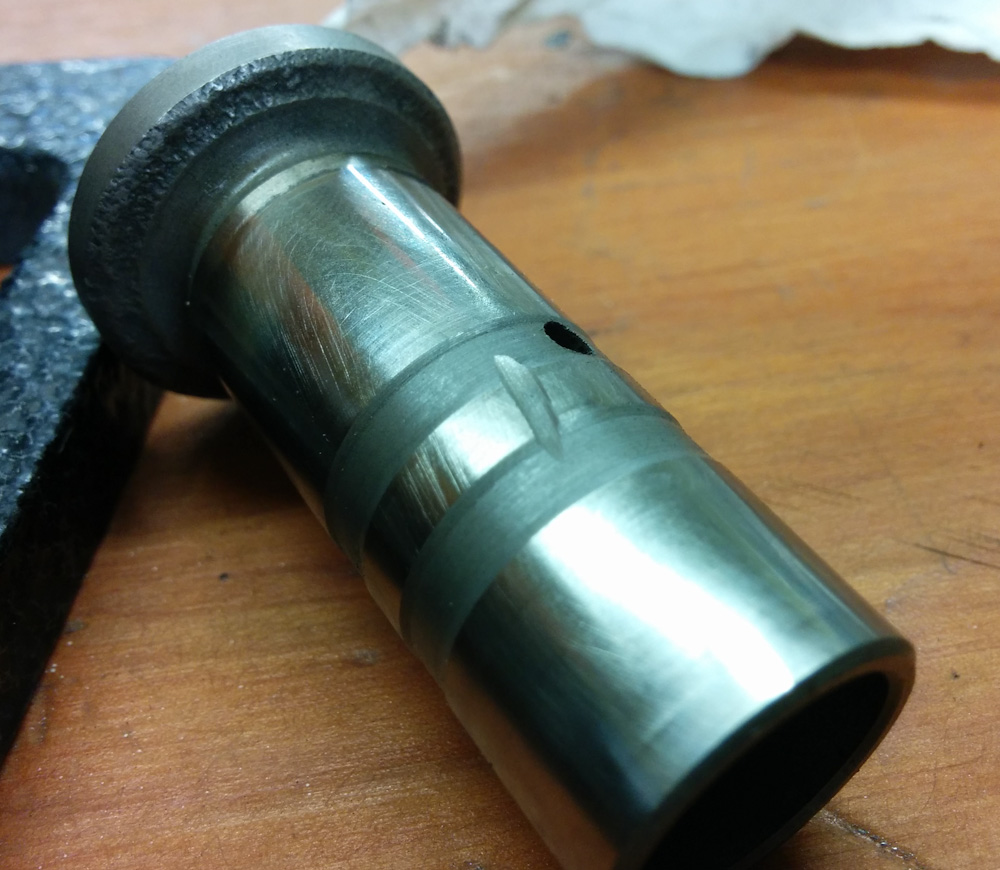
A lifter modified to increase the oil flow to the head. The hole in the upper groove supplies oil to the pushrod. The mod is to cut three connecting grooves between the two grooves, so that the one supplying oil to the pushrod gets a continuous oil supply even when the valve is not being actuated.
The fix, as shown in the picture, is super simple: You just grind passages connecting the two grooves. Three cuts, arranged roughly symmetrically around the lifter, in recommended. The biggest risk is letting the Dremel jump around on the lifter surface, but I managed to do all 8 lifters without any accidents. It only took maybe 15 minutes in all.
This way oil will flow to the head basically 100% of the time. This is supposed to not only decrease the risk of lubrication problems with the rocker arms, but the increased oil flow through the head also increases the heat transfer into the oil, since the cylinder heads are the hottest part of the engine. This should help cylinder head cooling (while increasing oil temperature, of course.)
The only possible drawback of these oil mods (which incidentally VW themselves incorporated into their next model, the Type IV engine) is that it may pump so much oil into the heads that there isn’t enough in the oil sump. I’ll monitor the oil pressure closely for signs of the pickup tube sucking air when we start running it again.
I also examined the wear on the lifters quite closely. While there the surface is noticeably worn, all 8 surfaces are still clearly convex. There is very minor pitting, as shown in the picture below. I was tempted to replace them since I don’t want to have to pull the engine apart again to change the lifters, but decided against it. I think they’ll be fine.
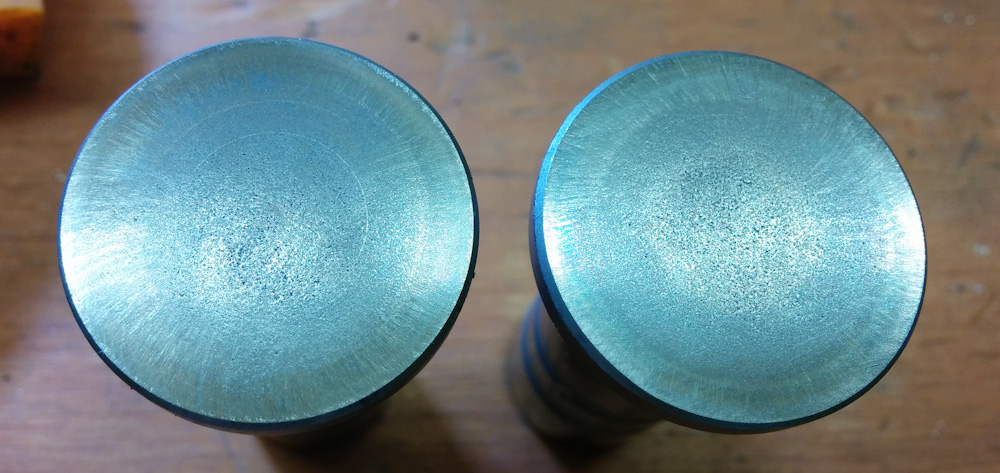
The lifter lobes have clear signs of pitting, but it is very shallow. The picture makes it look worse than it is. They can barely be felt when dragging a scribe over the surface.
The list of things that need to be done before the case can be put back together for good is getting shorter. Top on the list are balancing the new rods and pistons and verifying the cam timing. That’ll be the topic of the next post.
Pingback: Engine guts 13: Setting valve geometry – Patrik's projects