(In case anyone wondered why there was a lapse in updates, it’s because of this little guy who arrived on January 28. It’s gotten a bit harder to find time to work on the engine since then, although it’s so close to the end I’m going to try hard to get it done.)

Axel, the source of engine work delays…
Now that the case is closed, the next step is to set the deck heights. On a VW, the cylinder barrels are separate from the crankcase, and the combination of crankshaft stroke, connecting rod length, piston height, and compression ratio affects how close to the top of the cylinders the pistons come at top dead center. This is called the “deck height”, and must be set correctly since it affects the compression ratio of the cylinders.
The deck height can be adjusted in two ways. First, by adding shims under the base of the cylinder barrel. More shims here puts the cylinder further out from the case and hence increases the space between the top of the piston and the top of the barrel. Second, if the desired change is small, the pistons themselves can have their top surfaces fly-cut down a bit. You obviously don’t want to take away a lot of material this way, but since shims with thicknesses less than a millimeter aren’t common this is a way to get exactly the height you need.
There is another reason you might want to fly-cut the pistons rather than add shims: You can set each cylinder’s deck height individually this way. Since the heads go over both barrels on each side, the two cylinders need to have the same shims or their top surfaces, which seal against the head, won’t be co-planar. Now, ideally, the combustion chambers will have exactly the same volume and hence you want exactly the same deck heights, but in the real world that’s not the case. On our engine, the combustion chamber volumes are the same to within a cc. To get the same compression ratio on the different cylinders, this translates to a different deck height of about 0.1mm. Not much, but if you’re going to fly-cut them anyway, you might as well do it right.
There is another consideration with deck height: you don’t want it to too large. The combustion chamber only takes up a part of the cylinder cross-sectional area (see the pictures of the heads in the linked post above.) The rest, known as the “squish” or “quench” area, becomes very thin when the piston is at the top. If the piston came up exactly to the top of the cylinder, there would be no volume here at all and all the fuel/air mixture would be squished out (hence the name.) This is desirable for several reasons. First, it concentrates all the fuel/air mixture closer to the spark plugs and hence helps it burn more quickly. Having combustible mixture hang out far away from the spark plugs increases the risk of it spontaneously igniting before the flame front has time to reach it, so that makes the cylinder more detonation-prone, which is a bad thing. Second, as the mixture is squished out from the quench area into the combustion chamber, it creates turbulence which helps the combustion process. For all these reasons, you want to keep the deck height small, ideally no more than 2mm between the piston and the deck surface in the head.
All this means you really want a zero deck height. However, for practical reasons that’s not possible. You really don’t want the piston to hit the head and some clearance is needed to allow for thermal expansion, bearing wear, and the fact that the piston can cock itself slightly in the bore. For these reasons, people don’t recommend setting a deck height less than 1mm in the VW. So for an efficient, reliable engine, you’re constrained from both ends here.
With our engine, there is another concern. As shown in the combustion chamber post earlier, the spark plugs for the secondary ignition protrude above the deck surface in the head, with significant variation between the cylinders. When I test-fit the heads and turned the engine over, I could feel a slight interference when piston #4 reached top dead center. After removing the heads, a slight mark on the piston surface was apparent, corresponding to the location of the spark plug. Apparently the piston came too close to the head in this cylinder (which is the one where the secondary spark plug protruded the highest.)
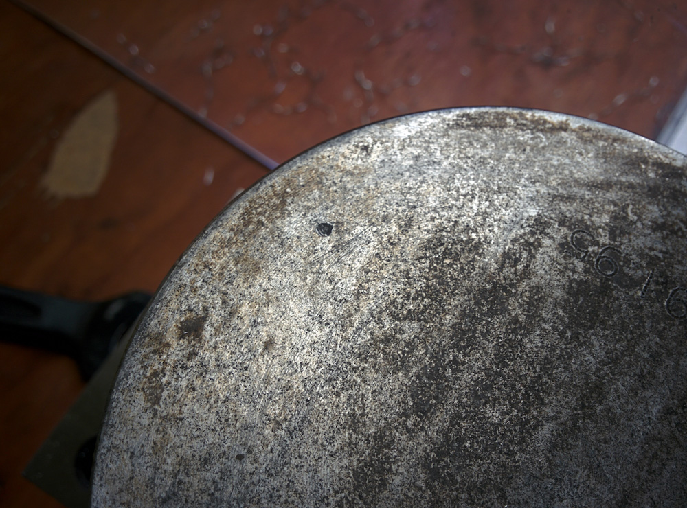
The mark in the center of the picture coincides with the location of the secondary spark plug in cylinder #4. Of all secondary spark plugs, this one protrudes the highest above the head. Apparently, the deck height used previously was too small, letting the piston hit the spark plug.
This wasn’t the correct deck height, I was just using a 1mm shim on all cylinders as a baseline, so it wasn’t an immediate concern. I was surprised, though, because by my estimation there should be clearance to all the spark plugs. Intrigued, I dug out the old #4 piston and, voila, there’s a clear impact mark in the same location! Apparently there has been insufficient clearance here all along.
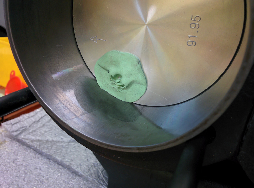
By sticking some clay on the piston, mounting the head, and turning the engine over, we get an imprint of how close various parts of the head gets. This picture confirms that the electrode for the spark plug has pushed all the clay out of the way and is contacting the piston. It also shows that the edge of the spark plug, which comes in at a shallow angle, also is very close to the piston.
I double-checked this by doing the classic “clay test”. By affixing a piece of clay to the piston tops and turning the engine over, you get an imprint of the head shape. By doing this on the four cylinders, the interference on the #4 piston was confirmed. It also showed that the spark plugs on the other cylinders were dangerously close, certainly violating the desired 1mm clearance.
This presented a dilemma: The 1mm desired clearance obviously applies to the highest point in the head. This normally is the head deck surface, but in our engine it’s the secondary spark plugs. If the deck height is set to clear the spark plug by 1mm, the result would be a too wide squish clearance, maybe 2.5mm, and too low compression ratio.
Since this engine will run 100 octane avgas, there should be plenty of margin to set a compression ratio a bit higher than the 8.0:1 recommended by Sonex for 93 octane and up. Based on what people have run in other aircraft VW conversions using 100LL, I decided to target 9.0:1, which results in a squish clearance of about 1.6mm. This is also more in line with what people recommend for our class of camshaft.
Given that we will also be using a 1.0mm copper head gasket, which adds to the combustion chamber volume, the desired deck heights come out as follows: (The measured chamber volumes include a 1.6mm head gasket, so the 0.6mm difference needs to be taken into account if anyone wants to do these numbers themselves.)
- Cylinder 1: Combustion chamber 66.4cc, desired deck height 0.70mm, measured 0.33mm, remove 0.37mm from piston top.
- Cylinder 2: CC 66.9cc, desired deck height 0.62mm, measured 0.20mm, remove 0.42mm.
- Cylinder 3: CC 66.9cc, desired deck height 0.62mm, measured 0.32mm, remove 0.30mm.
- Cylinder 4: CC 67.3cc, desired deck height 0.56mm, measured 0.14mm, remove 0.42mm.
The obvious solution to the clearance problem is to make a little depression in the pistons. It only has to be 0.8mm deep to give us the desired clearance. The big question obviously is: would removing 0.8mm material (in addition to the fly-cutting, which will remove up to 0.4mm depending on the cylinder) weaken the piston too much. There’s no easy way to answer this, but asking a few VW people their guess was that it would be OK. The area is close to the edge of the piston, and the piston crown gets progressively thicker the closer to the edge you get. The stresses also go down closer to the edge. It appears the piston is about 7mm thick in this area, so 0.8mm is not negligible but it’s only over a 15mm wide area. We’re also not pushing these pistons that hard, so there should be some margin.
Having decided on this course of action, I programmed the operation up in Fusion 360, figured out how to mount the pistons on the mill, and, after test-cutting on the old pistons a bunch of times, went ahead and modified them.
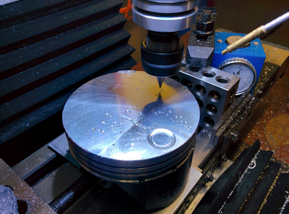
Modifying the new pistons on the mill. After fly-cutting the tops down the appropriate amount, a shallow depression was cut to improve clearance to the secondary spark plug.
Much more time was spent deciding on a course of action, doing the CAD/CAM, and testing than the actual cutting time. The job only took about 10 minutes per piston, and half of that was in tool change time. I made a movie of the entire job in case you want to vicariously follow along:
So that’s one more thing to check off the list. We should now have correct deck heights and compression ratios, without any risk of interference. In principle it’s now possible to bolt the cylinders and heads on, but I’ll hold off just a bit on doing that because first I want to verify rocker arm geometry and it’s nice to be able to test-fit the heads for that purpose. But it’s getting close!
Congratulations on the new guy. Now you’ll have a garage-helper.
Mine are 20 and 22 now, they grow up so fast but it’s good on both ends of the spectrum.
Pingback: Engine guts 13: Setting valve geometry – Patrik's projects
Very cool! If you modify the pistons individually, don’t you worry about balance? I thought the pistons and pins from Sonex came in a matching set.
Well, I did the same thing to all four pistons. But these were aftermarket pistons and VW parts are notoriously unbalanced so I had already balanced both pistons and connecting rods. I doubt the pistons Sonex sell are custom balanced, I think they’re straight from some VW parts supplier.