After dialing in the cam, I moved on to the final (I hope) grinding work that needed to be done before the case could be closed up: blueprinting the oil pump.
I had to get a new oil pump because the old one had the external connections for the oil cooler, which we will no longer use with the new filter setup we designed. There are a few small modifications that can be made to the oil pumps to increase their efficiency. (These are not new, they’re outlined in the book “Hot to hotrod VW engines” from 1970. Apparently the design of VW oil pumps have stayed the same for the last 50 years…)
The first step is to verify that the inlets and outlets of the pump actually line up with the corresponding passages in the case. VW Type 1 oil pumps are cylindrical and pressed into the front of the case. (The suction passage from the sump and the outlet going to the oil galleries are holes in the cylindrical surface.)
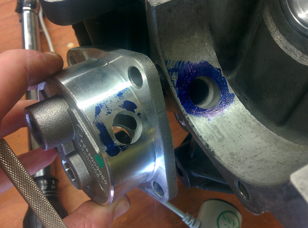
The first step of blueprinting the pump was to literally mark the passages in the case with dye and verify that they lined up with the passage in the pump. The inlet was pretty good, the outlet was not. Note how the blue-free region extends above and to the left of the hole in the pump.
As you can see in the picture above, the outlet in the pump was significantly offset from the case. This was corrected by upsizing the hole in the pump with the Dremel. There was probably also a corresponding place where the case should be opened up to match, but I was not willing to go that far — I’ve already cleaned the case out from swarf and plugged the passages up.
The next thing to do is to smooth the inlets and outlets on the inside of the pump. This is especially important on the inlet side, since pumps are sensitive to flow restrictions there. If there is too much pressure drop, the oil pump can even cavitate, which really ruins your oil pressure. The oil pump is a traditional gear pump, where the oil is transported in between the teeth of the gears. The inlet in the VW pump is mostly aimed at the driven gear, which makes it harder for the flow to go to the idler gear. The solution is to radius the inlet and open it up as much as possible towards both gears.
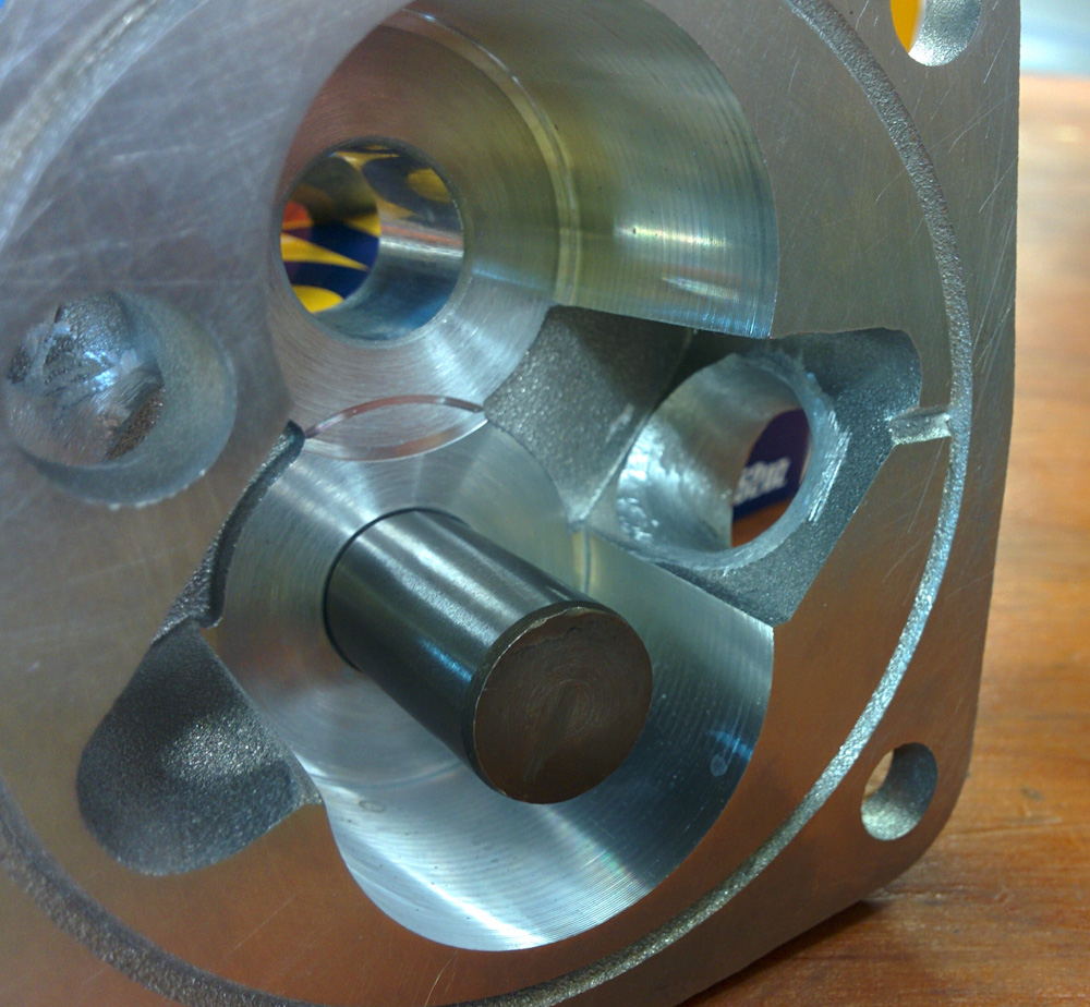
The pump inlet opening has been radiused to open more gradually, especially towards the front of the pump (although that’s hard to see in the picture) and towards the bottom gear. I could probably have been even more aggressive here, but this is a lot better than the sharp edges of the stock inlet.

The pump outlet shape isn’t as critical since this is a high-pressure area, but it has also been smoothed to avoid sharp edges. The pump also has this vertical outlet hole facing the front of the pump. This is used for attaching full-flow filter fittings, but has no function here. I did my best to round out those edges, too.
The final thing to check is the clearance between the pump gears and the lid at the front of the pump. Excessive clearance here gives the oil a path to leak back from the outlet to the inlet side and lowers the efficiency of the pump. This is especially noticeable when the oil is hot and less viscous. You want as little clearance as possible when cold here, since the aluminum pump body will expand more than the steel gears as the pump heats up. This clearance can be shrunk (but not increased) by carefully sanding the pump body down with sand paper against a flat plate.
The stock pump had about 0.20mm clearance, and the spec is <0.10mm. After some judicious sanding, I was down to between 0.04-0.05mm, as measured with a feeler gauge between the gears and the lid. That should be good.

This is the oil pump being mounted in the case, a small jump forward in time to after the case halves had been mated. (That will be in the next post.) The pump gears are coated with white lithium grease to help the pump “prime” when first started. Since there’s no oil there, the pump may not be able to suck the oil up from the sump without the sealing aid of the grease. The thin, blue coating on the lid surface is the “Hylomar” sealant.
The pump is tapped into the case after the case halves have been mated (which has happened and will be in the next post, when I get a chance to write it up.) The gears are coated with grease and mounted (the driven gear extends through the pump to the cam shaft, where it hooks into a slot) and finally a thin layer of sealant is smeared on the outer perimeter of the pump and the lid mounted. That’s all now done, so one more thing to check off the list.
Next will be actually closing up the case halves.
Pingback: Aerovee Oil Filter – Patrik's projects