After setting deck height, it was time to set the valve geometry or, rather, the rocker arm geometry.
The entire upper valve train is getting replaced, except the valves themselves. The valve springs have started rusting, and the engine also has dual valve springs which is way overkill for the cam and RPM we are running and only serves to increase the wear and lost power due to valve train friction.
Increased spring pressure is needed if you run the engine at high RPM since the springs provide the force needed to decelerate the valve train as the valves approach max lift and begin to close. The acceleration, and hence spring force, needed here is obviously proportional to the RPM, and if the springs aren’t strong enough, the valve train will lose contact with the cam lobe. This is called “valve float” and is obviously bad since then the valves are no longer following the cam profile. However, this becomes a factor when you go over maybe 6000 RPM or have cams with very aggressive lift profiles, and our airplane engine never exceeds 4000. Single high-pressure springs should be plenty for us.
The rocker arms also have to be replaced because the threads on one of the adjusters has galled. Normally, you could just replace the adjuster, but our rocker arms are apparently some special CB Performance made for a short period a decade ago in that they have 9mm threads rather than 8mm. You can no longer get 9mm adjusters, it seems, and an entirely new rocker assembly isn’t very expensive, so I elected to replace it. The new one also has better adjusters, more on that below.
Finally, if you replace the rocker arms with a different type, you need new pushrods because their length will change. So I also have a new set of 8 pushrods that need to be cut to the correct length. Which will be determined as part of the procedure here.
The first step is to replace the valve springs, which requires removing the valves. This requires compressing the valve springs, which in turn requires some sort of tool since these spring pressure is at least several hundred pounds. There is a dedicated tool you can buy to compress VW valve springs that makes this easy, the only problem is that it’s a large piece of metal that is prohibitively expensive to ship to Hawaii. So I decided to DIY my way through it. Once I saw how someone had done it online, it was simple: You use your drill press to push down on the spring, after having fabricated a tool that mounts in the drill chuck and fits on the valve retainer. Like this:
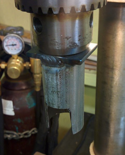
This is the DIY valve spring compressor. It’s a steel tube welded onto a steel rod so it can be mounted in a drill chuck. The tube is notched so you can get access to the valve keepers.
That took maybe half an hour to fiddle together, and it worked like a charm. In another half hour, all the springs were off. It’s amazing how having the right tool can make a job go from impossible to trivial….
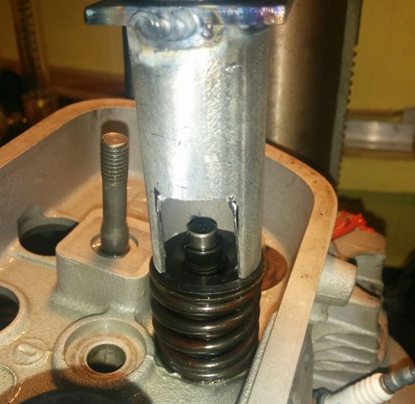
The valve spring compressor in action. It worked surprisingly well, especially given how crappy the drill press is. Note the rust spots on the valve spring. You really don’t want one of those to break, so that was reason enough to replace them.
With the valves off, it quickly became apparent that the valve seats were not in a good shape. They are made out of some sort of steel, and it clearly is susceptible to rusting.
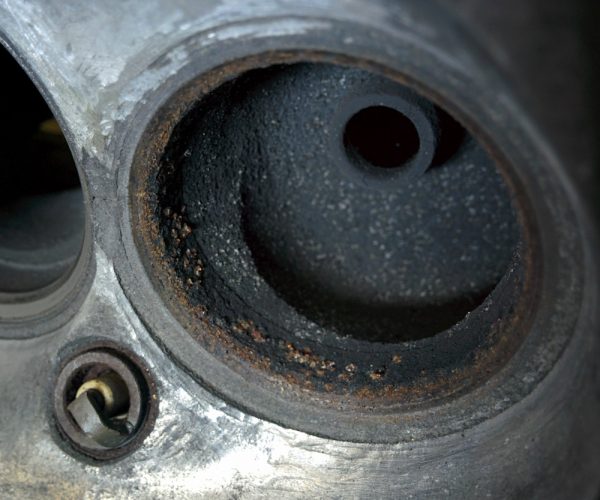
One of the exhaust valve seats after the valve came off. It’s clearly rusty and will need some freshening up.
Luckily I have some valve lapping compound on hand and after lapping them for a few minutes, the seats cleaned up fine. All except one of the exhaust valves, which did not look good. I gave it back to Bear’s VW so they could re-cut the seat.
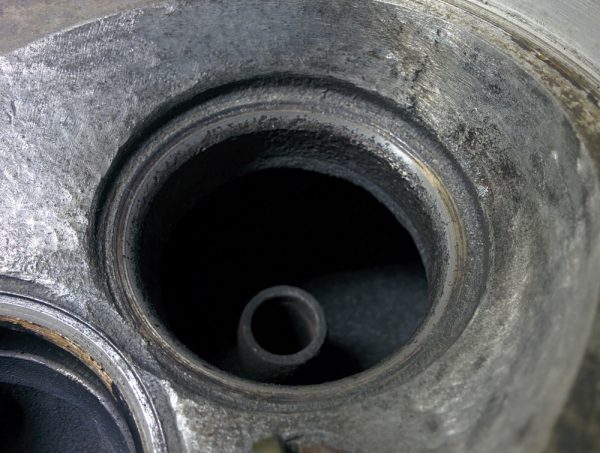
All the valve seats cleaned up nicely after some lapping except this one. There’s pitting all across the seat area, so this one went back to the VW shop to have the seat re-cut.
With all the valve seats reconditioned, the valves could be put back. However, it’s easier to fiddle with the rocker arm geometry if you don’t have to fight the valve springs all the time, so people recommend using some weaker springs for this. After a trip to Ace, I had the head back to looking like this.
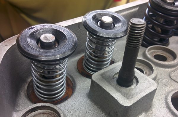
Cylinder #1 with the temporary valve springs used while working on the rocker arms. This makes it easy to push the valves in by hand and doesn’t put a huge load on the adjustable pushrod when measuring the pushrod length. The new valve springs are visible on the #3 valves to the right.
With the temporary valve springs, it’s easy to push the valves in either by hand or with the rocker arm, and the springs aren’t so strong they turn the engine, like the real ones do. Now, let’s talk rocker arm geometry. I’ve borrowed this figure from Bob Hoover’s HVX page so we have something to discuss from:
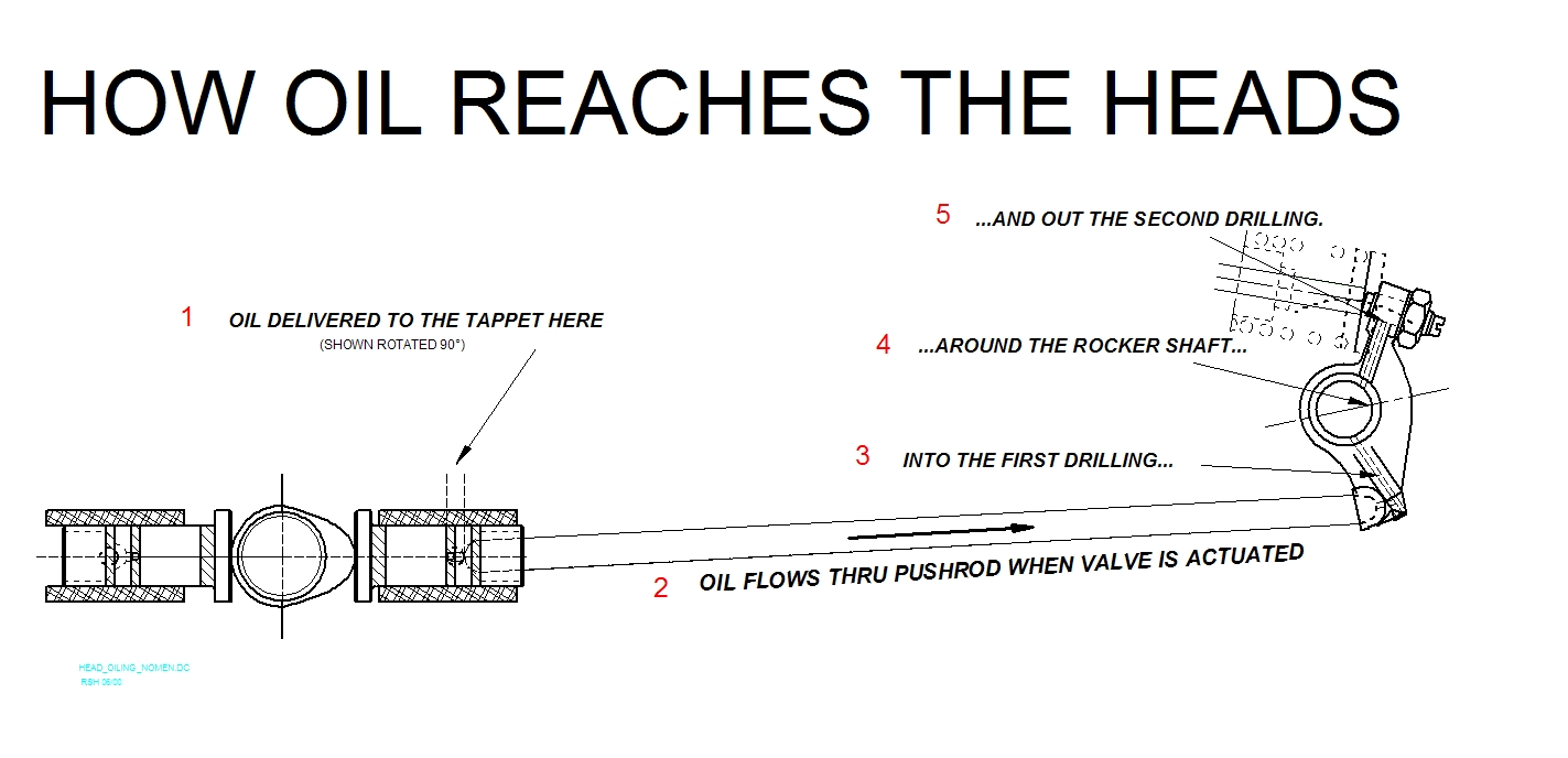
This image from Bob Hoover’s oil mods page shows the valve train components. It’s focused on oil flow but shows the layout pretty clearly. The valve stem and springs are shown faintly in the upper right. The rocker arm, which rotates around the rocker shaft (4) pushes on the valve stem, and in turn is pushed on by the pushrod (2), which is pushed on by the lifter (1) which is pushed on by the cam lobe over on the left.
There’s a lot of pushing going on here, but the basic function of the rocker arm is to reverse the pushing action of the pushrod, which is being pushed outward, away from the engine centerline, when the valve is actuated, into an inward motion of the valve stem. Because the rocker arm uses a rotating motion to generate a linear motion, it introduces a nonlinearity whenever the line between the contact points and the rocker shaft center is not perpendicular to the direction of the linear motion. Let’s expand on this further.
The pushrod end is spherical and sits in a spherical cup on the rocker arm. The inner pushrod end is pushed linearly outward by the lifter, but the rocker arm end has to move along a circle centered on the rocker arm shaft. The translation between pushrod linear motion x and the angle of the rocker arm α is x = R tan α, with suitable definitions of x and α. Since tan α ≈ α for small angles, we keep the nonlinearity small if we minimize the range of α.
On the valve end, the same thing applies. Let’s call the linear motion of the valve y and the angle of this side of the rocker arm β. We then have y = R’ tan β. We want to minimize the range of β, too. The same argument about nonlinearity applies on this side, too, but there’s another, more important reason. Unlike the pushrod, which sits in the rocker arm cup, the valve end slides against the rocker arm adjuster. The larger the value of angle β, the larger the sideways motion of the valve adjuster across the face of the valve stem. The sideways offset, which scales as cos β, should be minimized since it both wears the valve stem face and pushes the valve sideways in the guides, increasing valve guide wear.
If your eyes glazed over there, the conclusion is that to minimize nonlinearity and valve guide wear, we should minimize the range of angles traversed as the valve lifts, and that means we want to make the lines connecting the valve adjuster/pushrod cup and the rocker arm shaft center perpendicular to the valve stem/pushrod when the valve is at half lift.
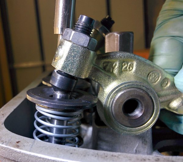
The rocker arms have adjustment screws at the valve end. There are two styles of adjusters available. The old rocker arms had “elephant’s foot” adjusters, which consist of a large foot with a swivel pad.
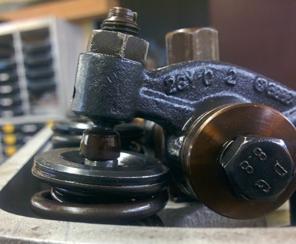
These is one of the old rocker arms, with the “elephant’s foot” style adjusters. The valve is at half lift here.
The new rockers have the other type of adjusters, the “ball” type (see pictures below). These have a steel ball which has been ground flat in one spot. The foot and ball both perform the same function, they swivel to take up the rotational motion of the rocker arm while contacting the valve stem on a large, flat area. This minimizes wear on the valve stem, in contrast to the old-style non-swivel rocker arms which have a cylindrical face that “rolls” across the valve stem as the rocker rotates. Since it’s cylindrical, it only contacts the valve along a line, so the contact forces are a lot higher.
The advantage of the “ball” type adjuster is that it has an internal oil supply. If you look at the schematic above, there’s a hole in the rocker arm connecting the rocker arm shaft to the adjuster thread, supplying the adjuster with oil. The ball adjuster in turn has a small hole in the center of its screw, so the socket in which the ball rotates is supplied with pressurized oil. The foot-type adjuster, on the other hand, does not. It relies on oil dribbling out of the adjuster threads and into the socket in the foot. Since I’ve gone through all this trouble increasing the oil supply to the heads, it seemed good to ensure the adjuster is well-supplied with oil. Having the oil spray out of the adjuster also serves to splash oil across the top of the head where it can absorb some of the heat from the exhaust port, although that may or may not be a noticeable effect.
In order to get as good a geometry as possible, it’s necessary to modify the rocker arms somewhat. It turns out the adjuster pokes out too far, so unless the rocker is modified, the pushrod will need to be cut too short. The solution is to cut about 1.5mm off the valve-side of the adjuster thread on the rocker arms. I did this on the mill, but the rocker arms must be made of some quite hard material because after cutting a few of them it started throwing glowing chips around. This is usually a sign that either the end mill is spinning too fast or, more likely, the end mill had dulled to the point that the cutting forces were putting enough heat into the material to make it glow. This was a bit disconcerting, and the quality of the cut had degraded noticeably by the time I got to the last rocker arm, but it worked very well.
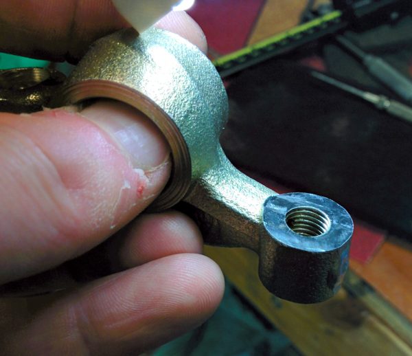
One of the rocker arms after cutting 1.5mm off the valve side of the adjuster thread on the mill. This makes it possible to put the rocker at a more optimal angle.
Before mounting the rocker arms for the final time, another small modification was called for. As part of the “HVX” oil mods to increase oil supply to the rocker arms, it is recommended to connect the incoming oil supply hole from the pushrod to the hole going to the adjuster by cutting a small groove in the inside surface of the rocker arm where it rotates on the shaft.
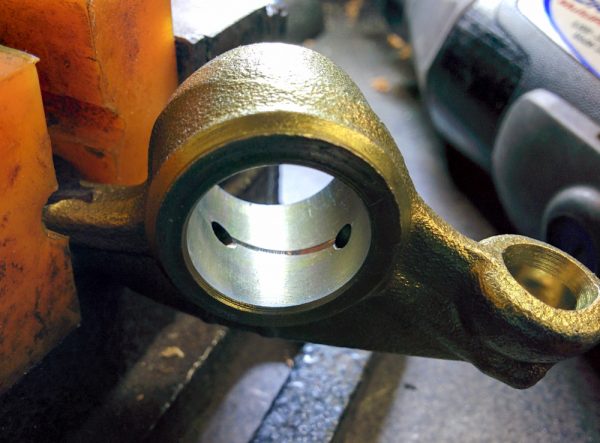
The groove cut in the rocker arm to enable oil coming in through the hole from the pushrod to pass directly through to the adjuster.
Without this groove, the only oil that will make it into the adjuster hole is whatever happens to ooze around the rocker shaft. The rocker shaft has a circumferential groove cut into it, but the two holes in the rocker arm are offset laterally so there is no way for oil to make it from one hole to the other through that groove. Since this involves using the Dremel cutting disk inside a fairly small hole, I practiced on four of the old rocker arms first to make sure that I could do it without having the Dremel go out of control and damaging the bearing surface.
With the grooves cut, it was finally time to start fitting the rocker assembly. From the analysis above, there are two angles that need to be controlled, the angle between the valve stem and the valve-side of the rocker arm (α above), and the angle between the pushrod and the pushrod side of the rocker arm (β).
The first angle, α, only depends on the position of the rocker shaft and is independent of the shape of the rocker arm, so it is set first. The rocker shaft can be moved by adding shims between the rocker assembly and the head. More shims moves the rocker shaft outward. We are looking for the position when the surface of the valve stem, at half lift, intersects the rocker shaft.
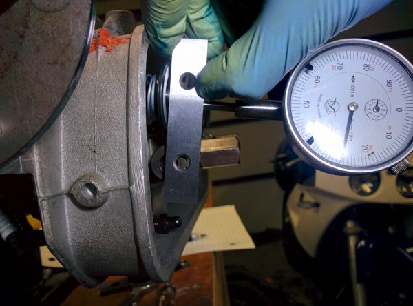
With the valve at half lift, the plane of the valve stem end, indicated here with the parallel I’m holding against it, should pass a distance away from the rocker shaft that is equal to the radius of the ball on the adjuster.
Actually, that is not quite true. I was confused about this for a while, but the place where rotating motion is converted to linear motion is the adjuster ball, not the valve end. Hence, it should actually be the line from the center of the adjuster ball to the rocker shaft that should be perpendicular to the valve stem. The ball center sits about 2.5mm above the end of the valve stem, so this means that the line of the valve stem end should intersect the rocker shaft center when the valve is at half lift – 2.5mm. With the dial indicator mounted against the valve retainer, this point is easy to find, and you can fairly accurately judge when the straight edge of the parallel in the picture above cuts the rocker shaft in half.
The sanity check is to then verify that the ball moves laterally across the valve stem face such that it’s in the same place at zero and full lift. (It’s not super easy to see this because the adjuster itself rotates and confuses the eye, but it served as a good enough sanity check that it alerted me to the fact that I had not taken the ball radius into account when I tried this first. This resulted in too few shims and a very clear tendency for the ball to slide across the stem more near zero lift compared to full lift.)
We can now compare the geometry at zero, half, and full lift:
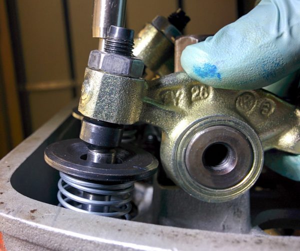
Rocker at half lift. The line from the center of the adjuster ball through the rocker shaft should is close to perpendicular to the valve stem, although it’s hard to see in the picture. The ball is also maximally outward on the valve stem in this position, compared to the pictures at zero and full lift.
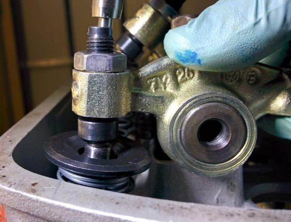
Rocker at full lift. Note that the lateral position of the ball on the valve stem is now very close to the same as at zero lift.
With the valve side of the geometry now fixed, we need to worry about the pushrod side. The pushrod side of the rocker (at half lift) can now be moved by screwing the adjuster in or out. We are looking for the place where the line through the center of the spherical end of the pushrod to the rocker shaft is perpendicular to the pushrod itself. I did not manage to take a picture of this, you need more than two hands to hold everything in place, but it turns out that there’s not much to do here. Even with the 1.5mm taken off the adjuster side, and the adjusters screwed as far into the rocker arms as possible, you can still not get the rocker arm to rotate far enough to get the other side into a perpendicular angle. This makes it easy, we just have to keep the adjuster as far into the rocker as possible (while retaining some adjustment range) and then cut the pushrod to a length that gives us the desired 0.006″ valve clearance.
In practice, the valve stem ends aren’t coplanar, though. The exhaust valve seats have apparently been recut more than the intake ones, because both exhaust valves poke out more than the intake valves. This means we can’t get the geometry correct for all valves, so we have to pick one. It turns out that the #1 exhaust valve that I’m using in the pictures above is approximately in the midway of the range, so that’ll work.
Since the valve stems aren’t coplanar, this also means that if we cut all pushrods the same length, we’ll have to take up the slop in the adjustment screws. I think it would be ideal to have every adjuster as retracted as possible, in order to get the pushrod end geometry as good as it could be. However, it would be a lot of work to measure and cut individual pushrod lengths for every valve (not to mention the possibility of getting them mixed up) so I’m going to accept this suboptimality.
The final adjustment that has to be done is to set the side clearance of the rocker arms on the shaft. There needs to be some free play here so the rocker arm can move freely and the oil can make it out from between the shaft and rocker arm. Too much free play, however, will make the rocker arm clack sideways when pushed by the pushrod, since the pushrods aren’t perfectly perpendicular to the rocker shaft and imparts some side load on the rocker arms. The old rocker shaft had gigantic free play, which makes for a noisy valve train and increased wear from all the sideways motion. The recommended clearance is 0.005″ (0.125mm) per rocker arm (the two center arms can move together, so they need extra play) which can be adjusted by adding shims on the rocker shaft. At the same time, these shims set the sideways position of the rocker arm on the valve stem. You want the rocker to sit somewhat off-center on the stem, since this makes the valve rotate slightly and makes it wear more evenly. There’s nothing particularly tricky about this, but you have to fiddle with the shims back and forth until you get both the correct play and the correct positions.
With the rocker geometry set and pushrods cut, we’re at final assembly. It is time to put the piston rings on, seal the cylinder barrels, and mount the heads for hopefully the final time.
Pingback: Engine guts 14: Final assembly – Patrik's projects
Pingback: Rocker Geometry – As good a time as any to learn it. – project żuczek