The balancing of the new connecting rods and the pistons is now done. They were within about 1.5 grams to begin with, so there wasn’t much to do.
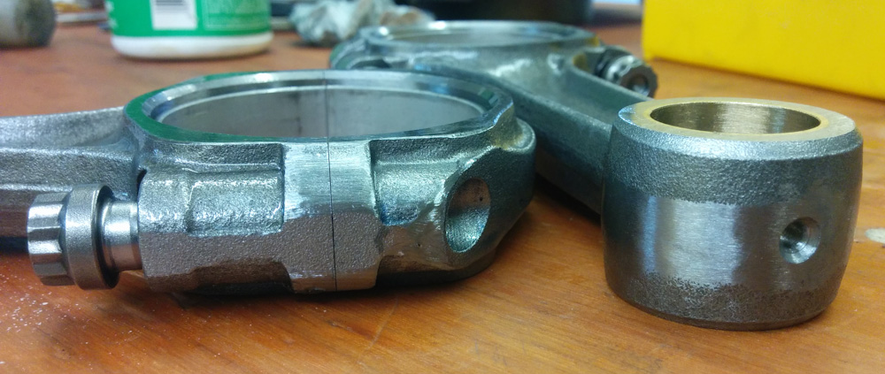
This picture shows how material was removed from the top of the small end to balance the small end weights, and from the area around the bolts for the big end.
Neither the rods, nor the pistons, had balancing pads. On the pistons I could see where material had been removed around the skirt for balancing previously, so there I continued grinding in that area. On the connecting rods I took material off the small end and around the bolts.
For posterity, here are the final weights:
- Rod #444: Small end 204.2g, big end 308.4g.
- Rod #476: Small end 204.2g, big end 308.2g.
- Rod #827: Small end 204.3g, big end 308.2g
- Rod #211: Small end 204.4g, big end 308.1g.
Those measurements don’t add up to the total weight of the rod, by the way, because the small end measurement is with the bolts included, but the big end was obtained by taking the total weight, without bolts, and subtracting the small end. Since all we’re looking for is for the numbers to be equal, it shouldn’t matter.
In the end both big and small ends are within 0.3g, not bad. For the pistons, we have:
- 489.0g. Pair with rod #444.
- 488.9g. Pair with rod #211.
- 489.0g. Pair with rod #827.
- 489.0g. Pair with rod #476.
The pistons are within 0.1g, and by pairing the heaviest piston with the rod with the lightest small end, we can further decrease the overall imbalance. This should not contribute to noticeable imbalance at the RPM this engine will see. (Of course, the real contributor to vibration is likely the prop. It would be good to get the entire rotating assembly dynamically balanced on the plane.)
One of the remaining things that will need to be done soon is setting the deck heights to get correct compression ratio. I started looking at how to mount the cylinders so they can be torqued down and the deck height measured and discovered that when you put shims under the cylinders, they don’t sit flat against the case.
The case head studs are threaded into steel inserts that are threaded into the magnesium case. (These are called “case savers”, since they save the case from having the threads strip out.) It turns out that most of these inserts were not threaded in deeply enough to go below the level of the cylinder flange surface in the case. This meant that when you added the shims, they actually rested on the edges of these four inserts rather than on the sealing surface on the case.
This is quite bad because, first, the cylinders were unstable and could rock back and forth since they were not sitting against a flat surface. Second, it also means there was a gap between the shims and the case, which is a recipe for a serious oil leak. It would also mean that if the shims gradually compressed where they were resting on the inserts, the deck height would change. The old shims had clear indentation marks where they had been pressed into the inserts.
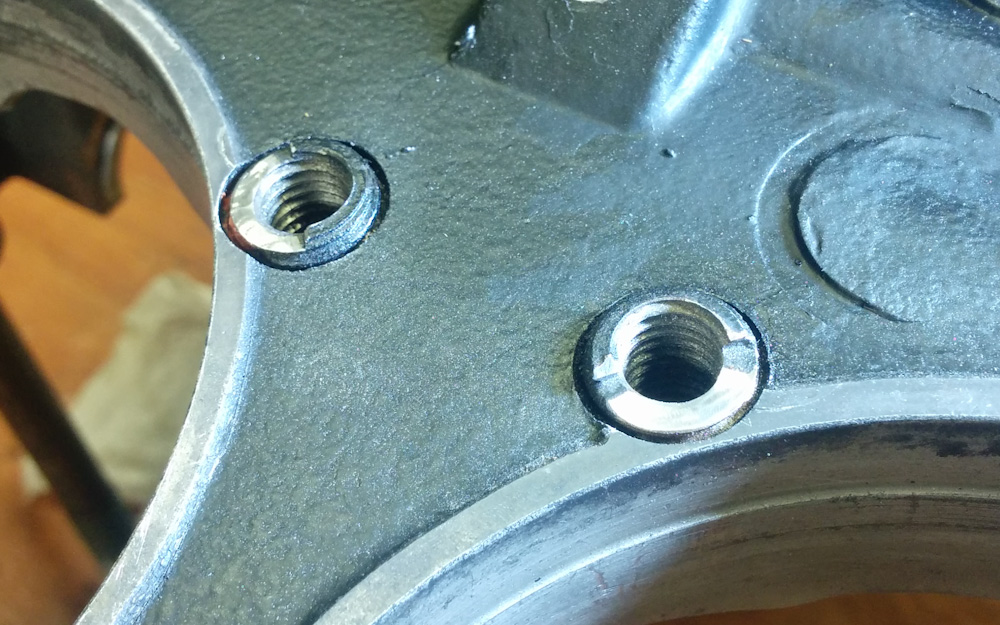
Two of the threaded “case saver” inserts. These have been carefully ground down so they now don’t protrude above the mating surface around the perimeter of the cylinder openings.
The solution was pretty simple. I went in with a small sanding wheel and very carefully ground down the steel inserts until they were below the flange plane, taking care to not nick the very narrow mating surface at these points.
Hopefully fixing this will mean less risk of oil leaks at the cylinder bases and a more reliable deck height setting.