This is it, the final post in the engine guts series!
After I had worked out how to do all the rocker geometry setup, as described in the previous post, it only took a morning to do it for the other head. Amazing how much more efficient things are when you know exactly what has to be done.
With the rocker geometry worked out, it was time to take off the heads and cylinders one final time and proceed with final assembly. This whole time the pistons have not had their rings, since that just makes it unnecessarily hard to turn the engine over, and the piston wrist pins not had their snap rings. Sealant also has to be applied to the base of the cylinder barrels to avoid oil leaks there.
This did not take long but I had to stop myself and go over the check list to make sure I didn’t stumble on the goal line and forget something. The base of the cylinders was sealed with RTV before, which is not what is called for. Most old assembly instructions call for Aviation Form-a-gasket, but these days there are better products available so I used Loctite 518 here.
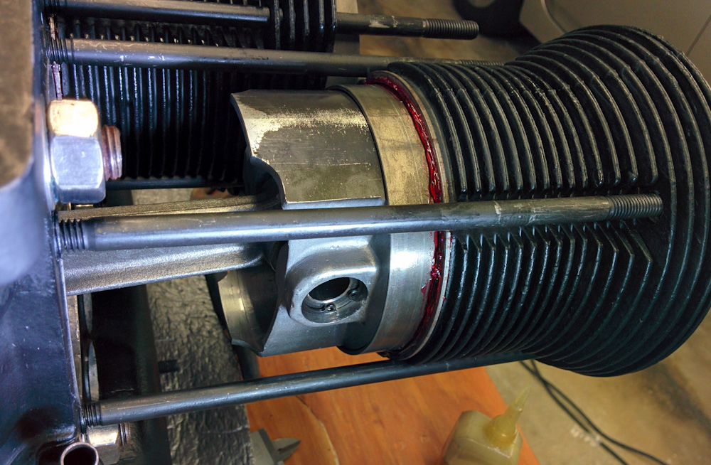
The cylinders go on for the last time, now with the piston rings mounted, the snap rings holding the wrist pin in place, and Loctite 518 applied to the base of the cylinder barrel and shim.
After putting the cylinders in place, the head goes back on, but first you have to remember to add the “SuperTin” baffle that snaps to the bottom of the cylinders. (I’ve forgotten that once back last year when I worked on it at the airport…) The pushrod tubes also have to be mounted. Since these were unused, the accordions were fully expanded. They were so long that it was hard to get any of the nuts on the head studs to engage so I could start compressing them. The pushrod tubes are a common location for oil leaks. They have silicone seals on the ends, but out of an abundance of caution I also applied a thin layer of Hylomar to the tubes and the mounting surfaces in the heads and case. Given how much they compressed as the head was tightened, I don’t think they’ll be leaking now. (It’s the next time the heads come off that you have to watch for it, because then the tubes will already be compressed.)
Since four of the stud nuts are inside the valve cover, it’s also possible to leak oil out past the washers/nuts, so I applied Hylomar to them, too. The Aerovee instructions don’t call for any sealant on these nuts, but other instructions do.
So, that’s it. As of now, both heads are on for good, and most accessories are bolted on. The pushrods are not mounted, however, because people recommend turning the engine over without spark plugs and pushrods until you have oil pressure. This avoids loading up the valve train without oil. It’ll be quick to mount them and adjust the valves once we have oil in the engine.
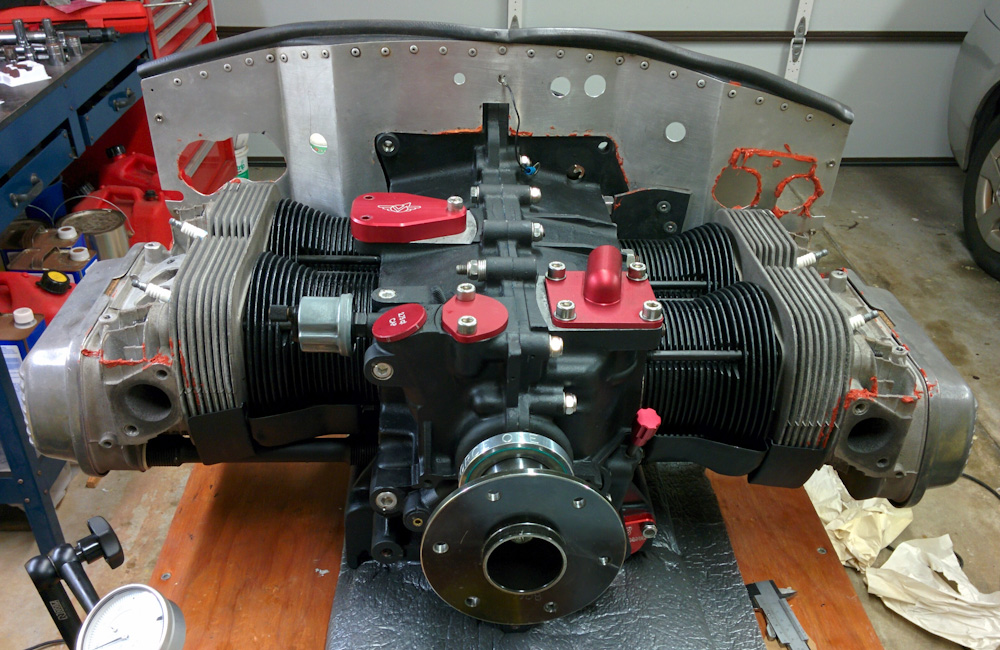
At last, the assembled Aerovee! It can now be hauled back to the airport so N132EA can stop looking like a jet wannabe.
The one biggish thing that remains, apart from hooking everything back up again, is fabricate the adapter that will mount to the oil cooler attachment on top of the engine and connect the new oil filter. The CAD is all done, I just need to spend some time on the mill to get it done.
Pingback: Aerovee Oil Filter – Patrik's projects