While working on the “oil mods”, I’ve also been trying to get the combustion chamber volumes more even, as I talked about two posts ago.
As so many other things, this became quite an ordeal. It turns out 2cc is a lot of material to remove. I’ve been grinding and measuring for what seems like days. I quickly realized I needed to start hogging out big chunks of stuff to get anywhere, but it’s hard to judge and you don’t want to make some gouges that are so large they can’t be smoothed out later.
The natural spot to remove material is around the extra spark plug, which now is quite unshrouded on the heads that had material removed from them. It’s a big difference compared to the original state, as you can see in the pictures below. This has lead to more shape differences than I liked but there’s not much to do about that. I’ll let the pictures tell the story.
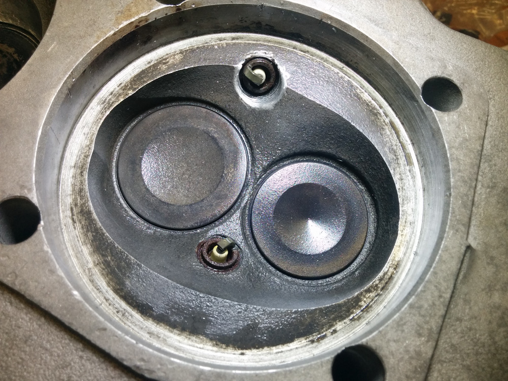
This is the, basically untouched, largest combustion chamber, cylinder #2, with a volume of 67.5cc. As you can see, the spark plug is set quite deep into the head. The only thing done here was to grind away the threads visible in the aluminum, as well as the 1-2 threads of the Time-sert insert barely poking out of the head on top. This also provides needed piston clearance.
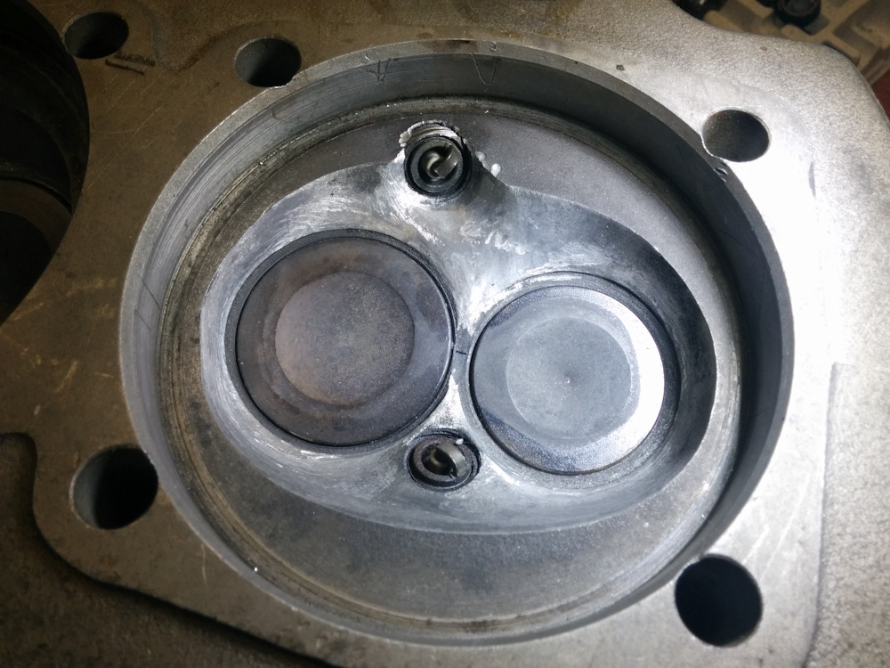
This is cylinder #3, which started out with a volume of 66.4cc. Comparing the location of the spark plug with cylinder #2 above, it’s obvious that it’s located much closer to the piston, which likely is the cause of most of the discrepancy. The cavity in which the spark plug sits has been opened up and rounded out to compensate. The area below the intake valve, on the left, has also been deepened to match that of #2 above. After this work, the volume has been increased to 66.9cc.
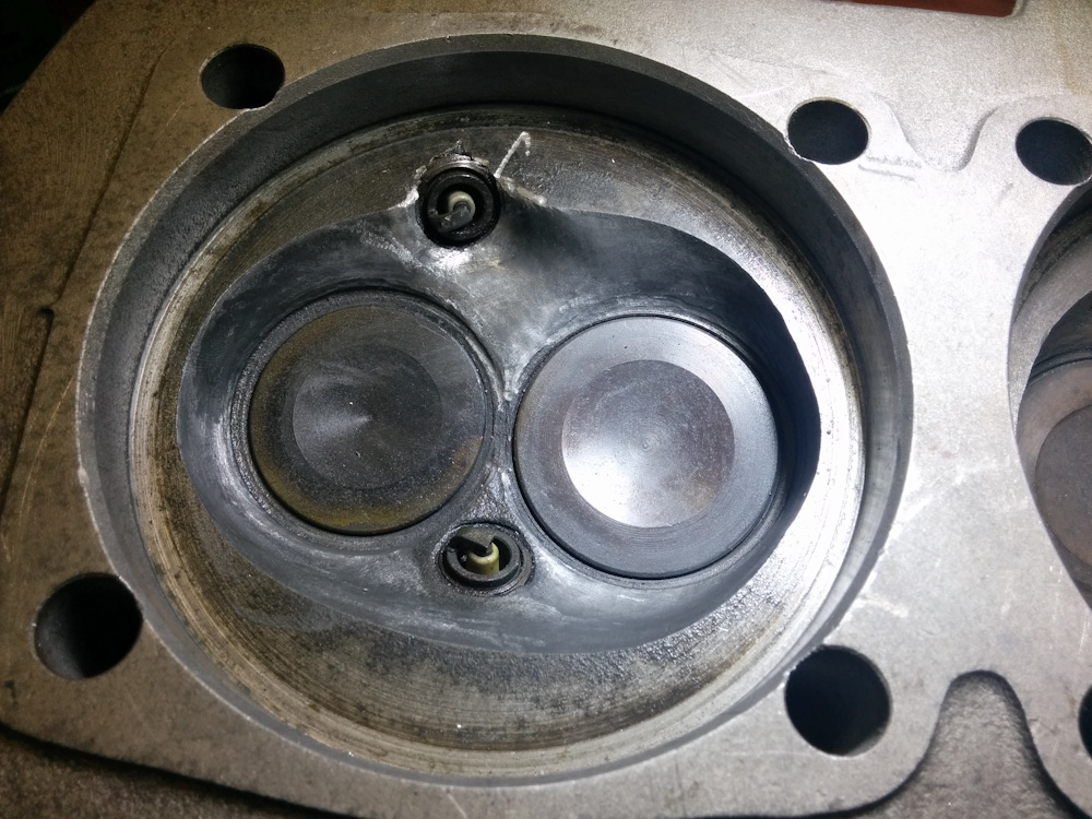
Cylinder #1, which initially started out as the smallest chamber at 66.0cc. In addition to having a “high” spark plug position like #3 above, also note that the secondary spark plugs, on top, are not mounted symmetrically. In this cylinder, it is toward the exhaust valve, while in the others above it is toward the intake valve. Because the chamber is asymmetric, this cuts the hole more “normal” to the chamber surface in this cylinder, which likely added to the difference. This chamber was treated in much the same way, except the spark plug cavity was made even wider. Even with this amount of work, the chamber has only been increased to 66.4cc.
At this point the chamber volumes are 66.4, 66.9, 66.9, and 67.3 cc. This is a spread of 0.9cc, which I’m going to call good since I’m really not comfortable removing as much more material from #1 as I already have, which would be the required amount to get #1 into better balance with the others.
I’m not so excited about this amount of discrepancy, and the asymmetry of the spark plug placement bothers me. I know it’s not by much, but it’s gotta contribute to uneven combustion between the two sets of cylinders.
While I had the heads and the Dremel out, I decided to do some work on the cooling passages. It’s extremely important that air can flow through the cooling fins around the exhaust ports. These holes are often blocked by casting flash and need to be cleaned out. I’d done some of this back when I had the heads at home for the spark plug thread repairs, but not as well as it should be.
After finding some pictures online about how the holes should look (and probably also having gotten over my hesitation of cutting into the heads) I went ahead and drilled most of the holes. The long “aircraft drill” used in the previous post came in handy here, since these holes are quite deep.
These holes were opened up drastically using drill bits. The exhaust port is right below them, so cooling is critical here. The small hole on the right goes quite near to the casting for the exhaust valve guide. There was no opening here before, and I probably had to drill through 5mm of material to break through. It’s not a big hole, but it should improve the cooling here a lot over the previous situation with no airflow at all.
Having “opened up” those holes, I got a bit innovative and figured I could make some holes near the exhaust flange, where there shouldn’t be any.
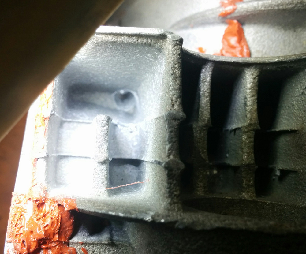
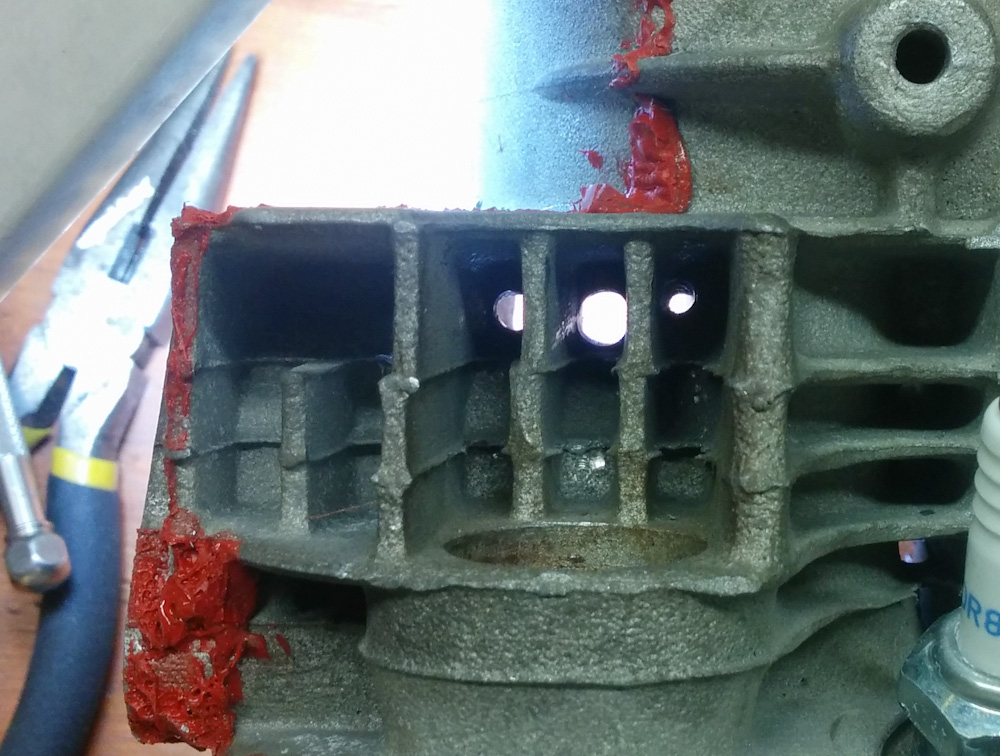
This is the area closest to the exhaust port flange, which did not have any air passages before. It’s not possible to go all the way through the head here, because the head stud on the other side is in the way. It is, however, possible to drill diagonally. (Sorry for the bad picture, it was hard to get sufficient lighting here.)
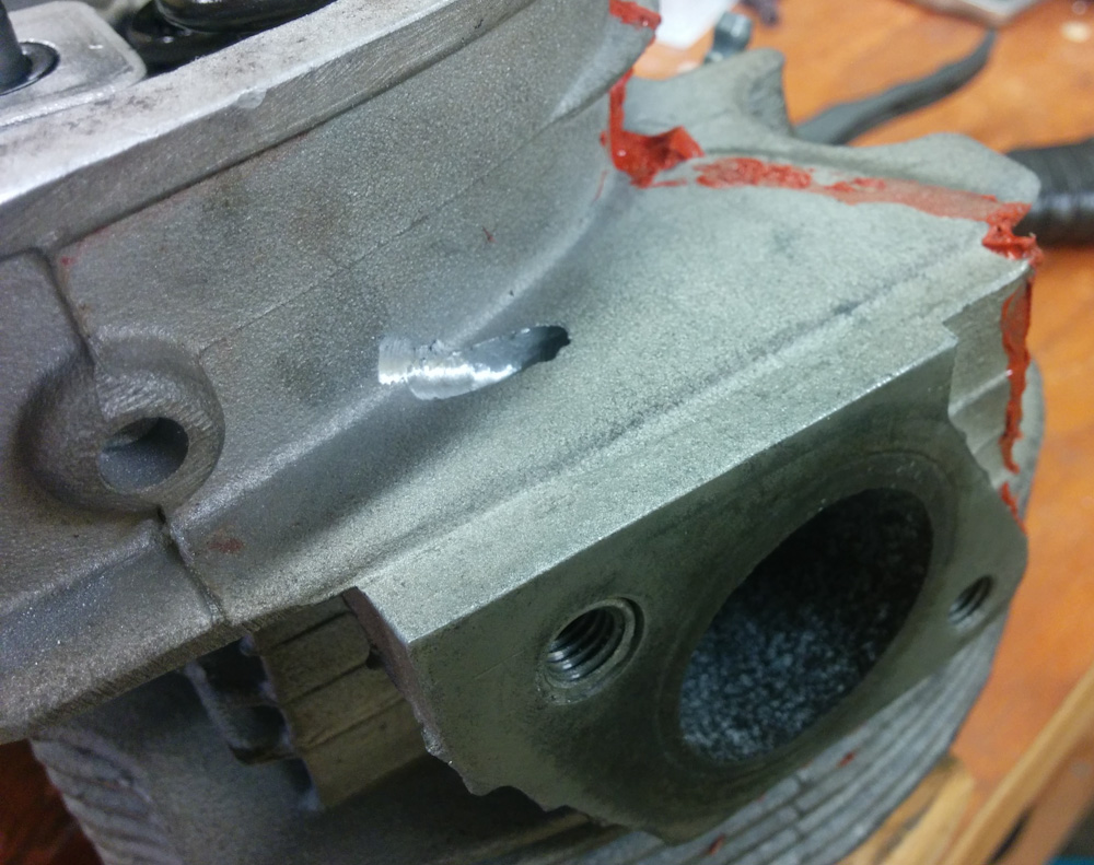
This view shows the other end of the hole near the exhaust flange, and also makes abundantly clear that drilling straight through the head was not an option. The red RTV line to the right marks where the baffles go, so this hole will exit on the low-pressure side of the baffles, as it should.
Hopefully enlarging these holes will provide some sorely needed improved cooling to the exhaust port area of the heads.
While reading about where there should be air passages in the heads, I also came across an interesting note by Bob Hoover. The area between the cylinders has a fairly large air passage, without fins, seen below.
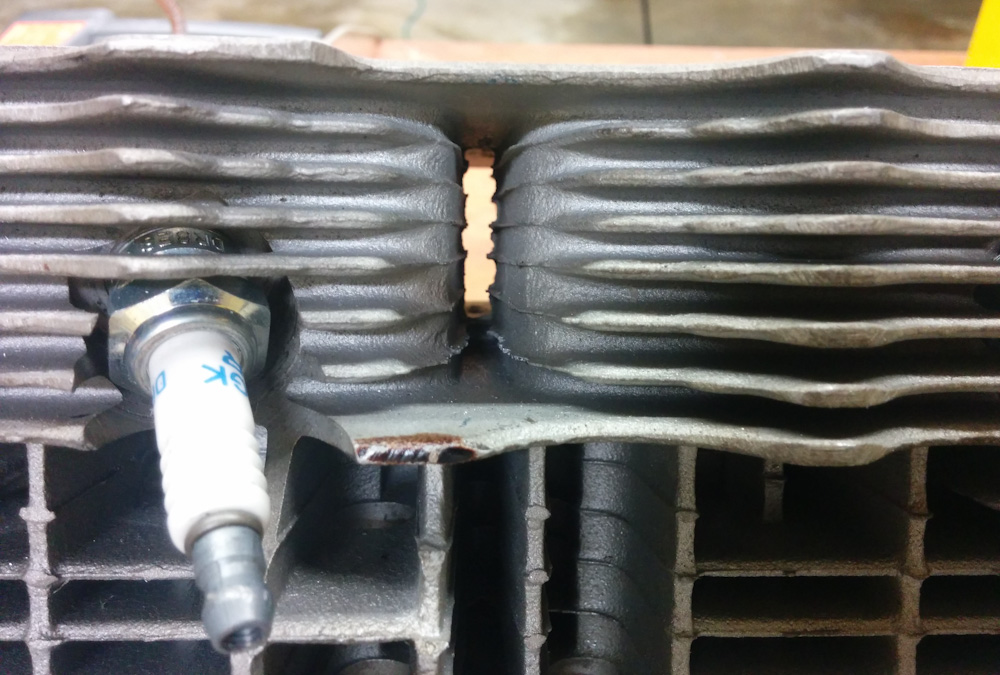
This rather large hole allows a lot of air to pass through and exit the bottom of the head without doing much cooling.
Apparently on the stock VW heads, there is a blocking plate in this location, forcing the air to spread left and right through the cooling fins on the bottom of the head rather than just go straight through. I have not seen this described anywhere else, it’s certainly not part of the Aerovee instruction. It makes sense, though. It should look something like shown below.
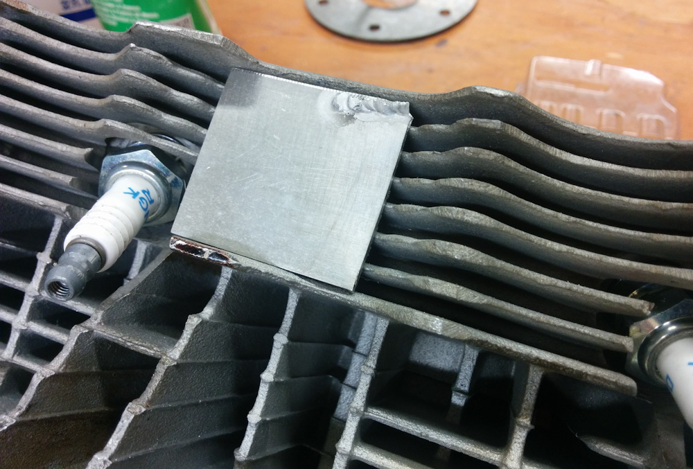
I rough-cut a piece of aluminum plate to the required size to see how it would fit. The fins have a square-shaped depression that indicates that there really should be something here.
By forcing that air to take a more useful route, it will accomplish two things: First, it will do some cooling work. Second, because it will encounter more flow resistance, it’ll increase the overall air pressure above the engine which will help push more air through the smaller passages. (Unless we have a big-ass air leak somewhere else, that is.)
I’ll certainly go ahead and add plates on our heads in this location when replacing the heads. It should be simple to cut squares of aluminum sheet and RTV them in place on the fins.
RTV?
http://lmgtfy.com/?q=rtv
Pingback: Engine guts 12: Setting deck height – Patrik's projects