Coming up on a year without a post… I now have a long backlog of stuff that’s happened that I’ll try to quickly go through. Starting with the big house project of 2025!
The house we purchased when we moved to Sweden has a floor heating system driven by something I’d never encountered before: an “exhaust air heat pump”. This is a type of air-source heat pump that combines heating and ventilation. It does this by using the room-temperature inside air being exhausted for ventilation purposes and extracting heat from it to heat the water in the heating system. So the air being sent outside is cold, typically between -10C and -15C depending on how hard the system is working, and from that you get essentially “free heat”. Sounds good, but there are numerous problems with this idea.
The first thing that should be obvious is that there’s no free lunch. The air being sent outside must be replaced, which it is through numerous fresh air vents sucking in outside air. This air is obviously the outside temperature, and it must be heated to room temperature by taking heat from the house. The only way there’s a net energy gain is thus if the air being exhausted is colder than the outside temperature. So this works great if the temperature outside is above freezing, the extra 10-15C the heat pump extracts from the exhaust air is sufficient to heat the building (and provide hot water).
But once the temperature outside hits about -10C, the game is up. You’re now only breaking even, the air coming in is the same temperature as the air going out, and the only net heat you’re providing to the building is the energy consumed by the compressor in the heat pump. If it gets even colder, the system must use backup electric heat to provide sufficient heat. And electric heat is neither cheap to run or an efficient use of resources.
An additional problem is that the outside air coming in through the fresh air vents causes extreme drafts in the winter. Even if the temperature in the house overall is fairly pleasant, if you happen to be near one of those vents when it’s -20C outside, you feel icy cold air blowing on you. Not very comfortable. The vents themselves would even ice up, and then as it got warmer water started dripping on the floor.
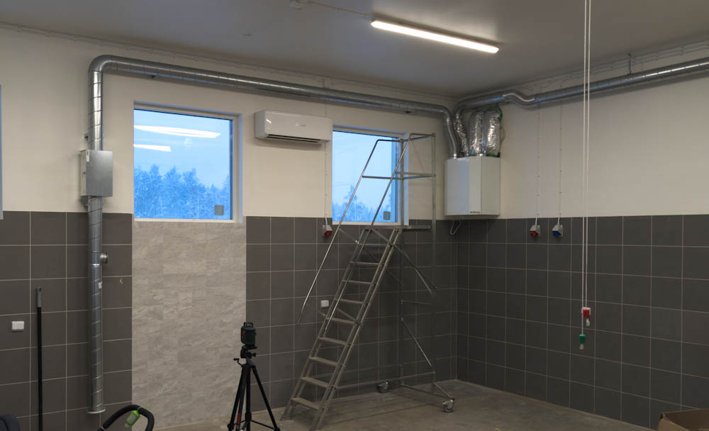
After just a few months into the winter of 2023 (which admittedly was pretty extreme) I had basically decided this system was sh**. There are better ways, especially for homes in cold places. The gold standard for heating systems in northern Sweden is the ground-source heat pump, or “rock heat” as it’s called in Swedish. This is typically done by drilling a very deep hole (like 250m or 750ft) into the ground, dropping a loop of hose into this hole, and then circulating a liquid through it. The temperature at those depths is basically equal to the annual average temperature, so what you have is a large reservoir of heat at a temperature between 2C – 8C, depending on location. By circulating this liquid into a heat pump, you can extract heat with fairly high efficiency all year around. The alternative is an air-source heat pump, which uses outside air as the heat source. (This is how the garage was heated.) These are cheap to install since they only need a fan and a heat exchanger, but since the efficiency drops as the air temperature drops, they’re least efficient exactly when you need the most heat. The garage unit would fail to keep the temperature in the garage once the temperature dropped below about -15C.
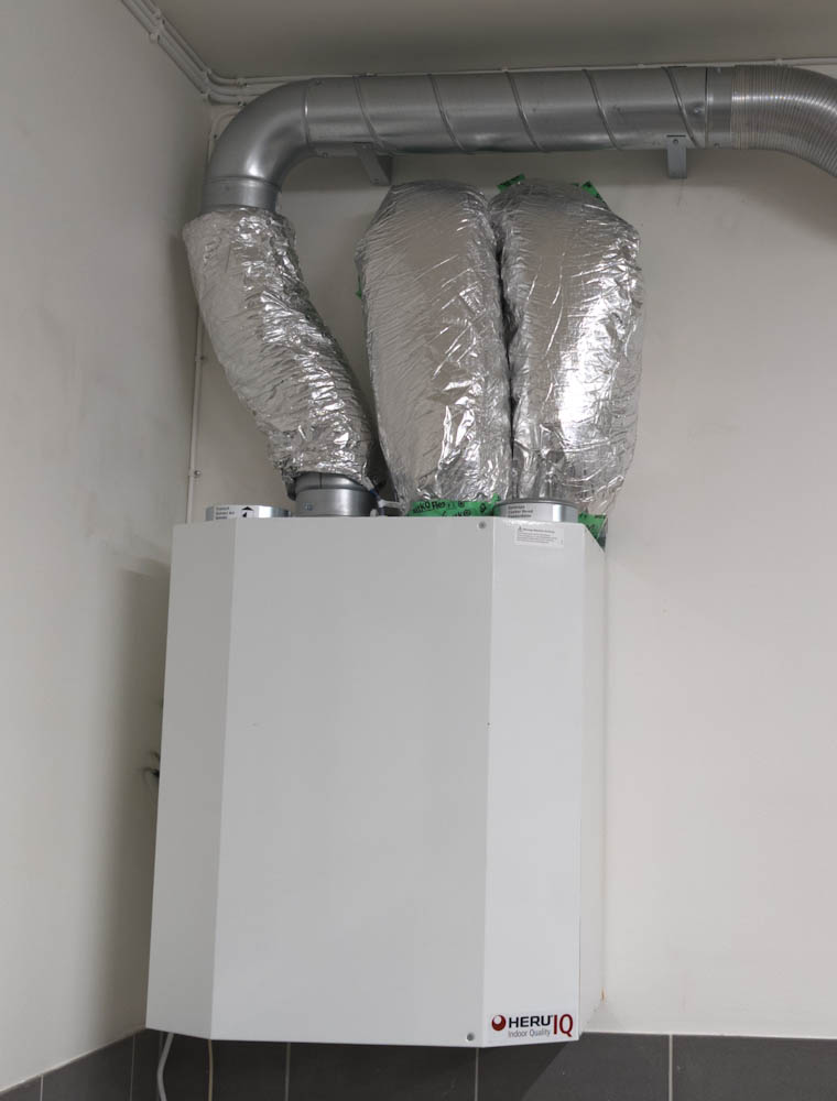
If we got rid of the original heat pump, though, we’d also need a new method for ventilation since it combined both. Here, the gold standard is the “mechanical supply and exhaust air with heat exchange”, or FTX as the Swedish acronym goes. (I already installed a small such unit in the garage.) This uses two fans, one to extract inside air and one to supply fresh outside air into the house. The two airflows go through a heat exchanger where the extract air gives up its heat to the supply air, meaning that the air coming in is heated to almost the same temperature as the inside. The drawback is that, unlike the original system, you need two sets of ductwork, one for the extract air and one for the supply air. This meant that installing such a system would entail a major overhaul of all the ductwork in the attic. But from an energy efficiency and comfort point of view, there was no contest. Plus it sounded like fun, so of course we decided to go ahead with it.
About a year ago we started the process of getting quotes for the drilling of the energy well and installation of a new heat pump. In the process, we’d also get rid of the separate heat pump in the garage and run pipes from the house to the garage so it also could use the same heating system. I attempted to figure out the power needed by the house and the garage in several different ways and landed on about 12kW at the “design outside temperature” which is -24C here. This in turn sets the size of the heat pump and the depth of the hole needed. 250m is the deepest hole commonly used, beyond that there are diminishing returns and it’s more efficient to drill two holes instead. 250m should be about right for us, maybe a little on the short side for a real cold winter, but we’ll have to see.
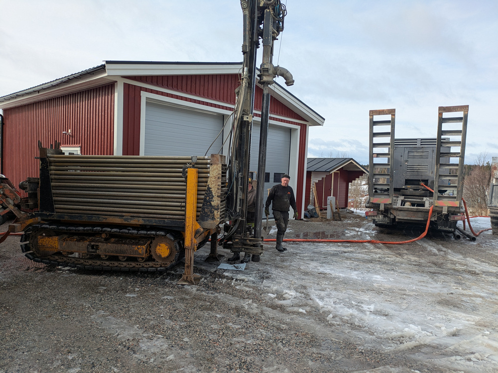
After getting the quotes we settled on Lelles Brunnsborrning to do the work, and by March it was time to start drilling.
This is the drill rig, in the process of drilling the 250m deep energy well in the driveway.
It was somewhat complicated to figure out exactly where to drill the well. We already have a well for drinking water, and local rules say you can’t drill within 30m of that. You also can’t be within 30m of the septic system, because there is a (very slight) chance of the drilling operation causing a crack in the rock that could allow the water being released from the septic system to reach ground water. This pretty much restricted the location to our driveway, but there’s also a water main and our electrical supply crossing our property right about there. On top of that, they want at least 4m distance to any structure. Running out all these constraints we ended up with about 1 square meter where we could do the drilling.
Drilling took 2 days and by the end of it we were left with two little pipes coming out of the ground.
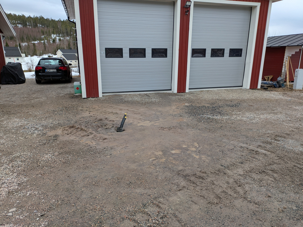
Once the drilling was done, all that was visible of the 250m deep well were the temporary pipes poking out of the ground.
The next step was to run these pipes into the house. This was done by another crew that showed up the next week to dig a trench and bury the connections. This digging had to be done a bit more carefully, because we crossed not only the electrical supply to the house but also the fiber connection for the internet and the power to the water well pump.
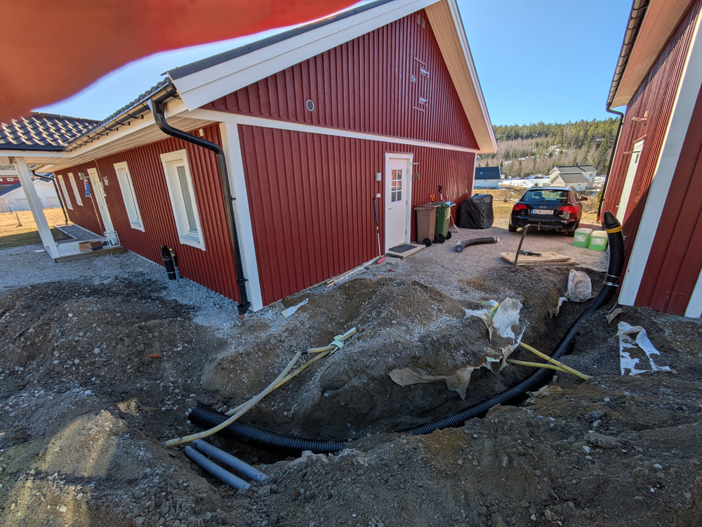
The supply tubing from the borehole to the house (the two gray insulated pipes) and the insulated tubing supplying heat to the garage (the fat black tube), were buried in the driveway. The yellow tubes contain the electrical and fiber connections.
The final step was to run the connections through the house wall and install the actual heat pump along with associated plumbing inside. This happened at the end of April. Since our system was a bit special with the separate connection to the garage (I was going to do the garage work myself later) I had a bunch of discussions with Daniel and Patrik at Lelles to make sure we were on the same page. Patrik (not me) who did the inside installation did a really neat job and in early May we were ready to turn on the new system.
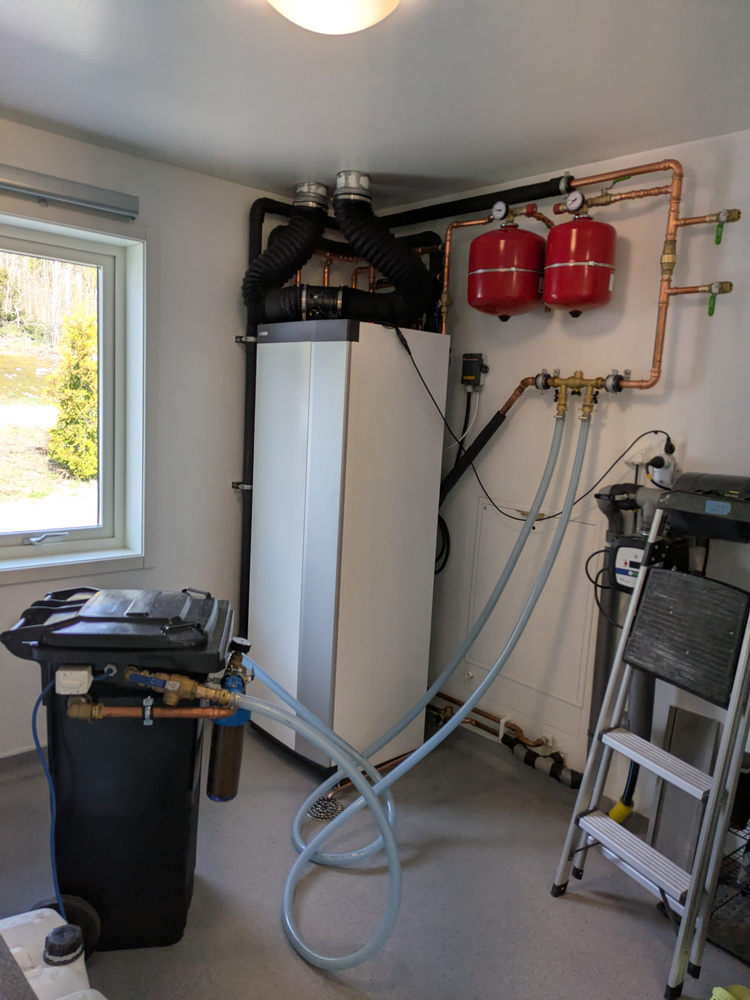
The new installation with the Nibe S1256 heat pump and associated plumbing. The trash can in the foreground contains the pump used to fill the “cold side” with a mixture of water and ethanol. On top of the heat pump is a small duct fan temporarily running the ventilation.
Now we needed a ventilation system. That’s the next post.