It’s finally time to close up the case. But first a little tidying up.
There’s been a small amount of binding when turning the crankshaft with the Force One bearing mounted. Over perhaps 120 degrees, it was harder to turn than seemed normal. I had measured earlier that the prop hub had a runout of about 0.002″/0.05mm. If the bearing was mounted slightly off-center, it would rub against the journal when the two pointed against each other.
I spoke to Great Plains, who said that most of the time when there is binding in the bearing, it’s because the hole dowel pin that hold the bearing in place isn’t drilled deep enough and it’s squeezing the bearing. I verified that was not the case since removing the dowel pin completely didn’t change things. I also determined that it was not the bearing that was uneven, since rotating the bearing in the case did not rotate the point at which the crankshaft was binding. The only conclusion was that the shop that bored the case to mount the bearing did not get it perfectly centered.
Since the effect must be very small, I decided to try an experiment. I added some lapping compound (30 micron) to the bearing (which is aluminum), bolted everything together, and turned the crankshaft for a few minutes. This got rid of the binding. After taking everything apart and cleaning up the bearing, it was clear that some material had been taken off at a section. I continued with 12 and 5 micron compound to smooth the surface out. After this exercise, the bearing now spins without any noticeable binding.
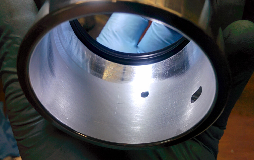
This is the side of the Force One bearing that was abraded the most by the lapping compound, as evidenced by the matte area.
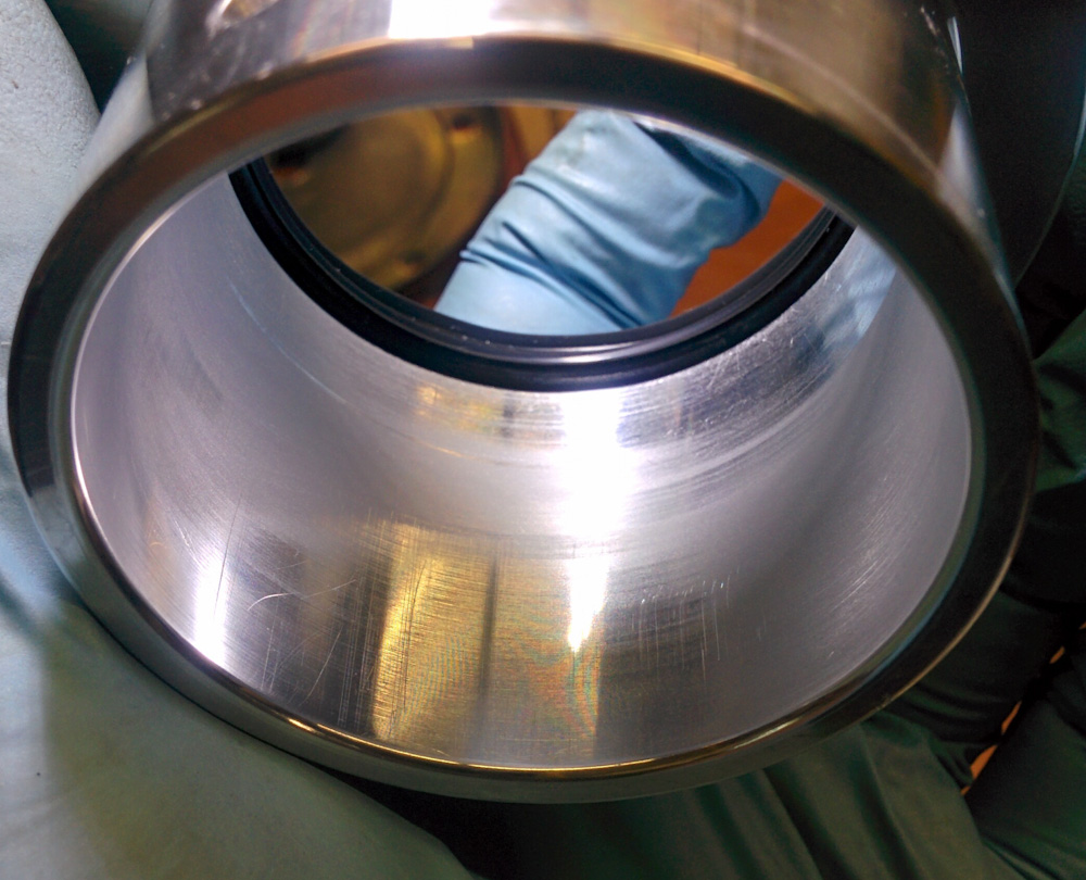
The other side of the bearing. This one still got cut a little bit, but is mostly untouched. By the pattern it looks like the bearing is actually mounted slightly cocked in the case.
Unfortunately I don’t have the equipment to measure the clearance between the bearing and the journal. It would be good to know whether this operation cut too much material so the bearing now has too much clearance. The guys at Great Plains couldn’t give me a number on what the expected clearance is, though.
Another little thing that had to be done was to notch the cam bearing by the flywheel for the oil return passage. Another example of the half-assed fit of these parts.
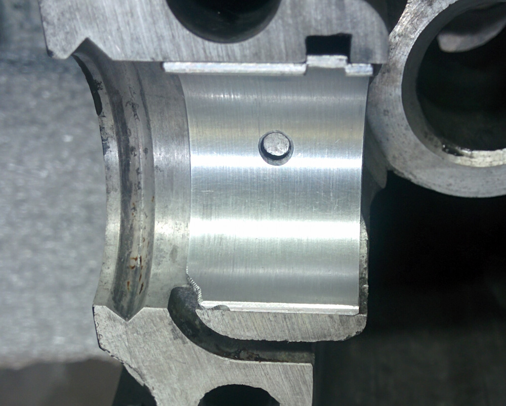
The cam bearing on the flywheel end of the case was a tad bit too wide and partially blocked the oil return passage, so it had to be ground back a bit.
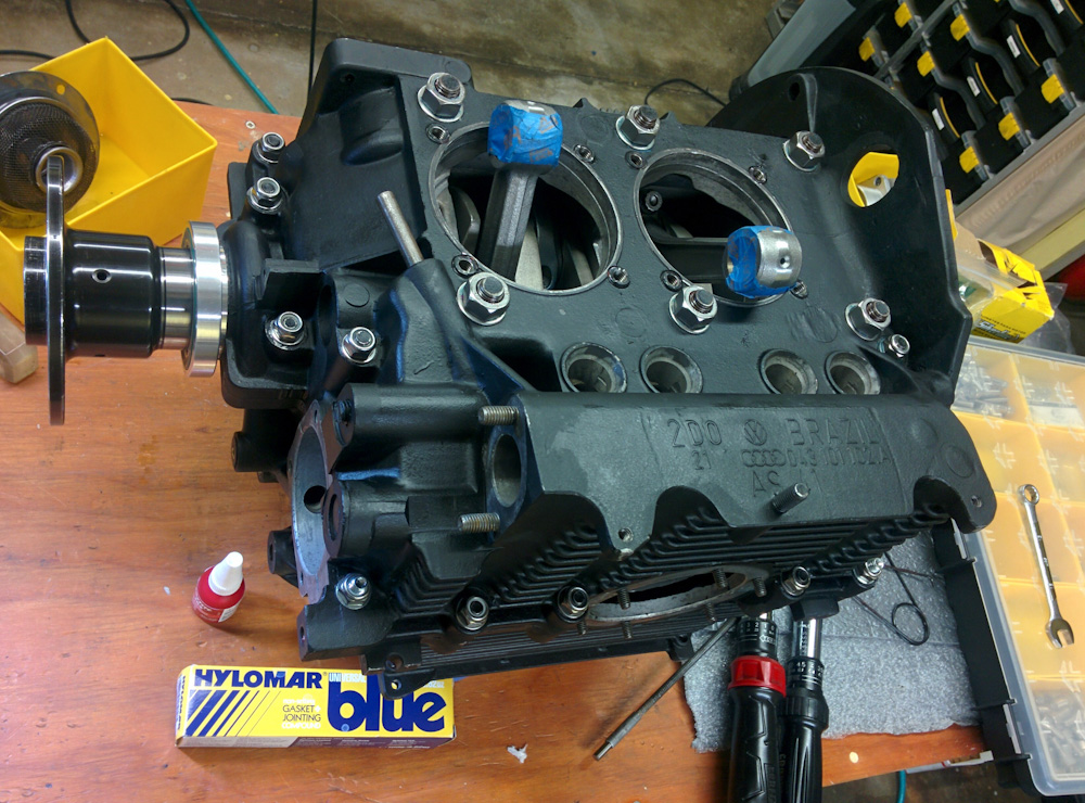
Finally, it was time to close everything up. For sealing the case halves, people highly recommended Hylomar, a non-setting gasketing compound that supposedly works very well in situations where it’s important that there be absolutely no buildup, like the case halves that are already a very close fit. It’s a translucent blue, very thin, material that smears out to practically nothing. I applied it all over one of the halves.

Hylomar sealant applied, in a very thin layer, to the case halves without studs, where it’s easier to get it around all the bolt holes.
Checking once again that everything was ready: all the bearings seated correctly, all 8 lifters greased and in place, cam plug in place, cam gear meshed correctly, rubber seals in place on all 8 main bearing studs, cam gear bolts torqued and loctited. I attempted to get the case halves to mate. I’ve done this for fitting purposes probably 25 times by now and never had a problem, but the one time I’d applied sealant would of course be the time where they did not go together properly.
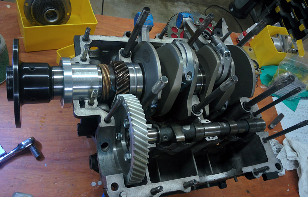
Everything’s ready to go together.
Taking them apart again, I noted a cam bearing had slipped out of place slightly. Luckily the case flange surfaces never actually mated so the sealant was undisturbed, and the second time everything went together OK.
To avoid oil leaks, I also applied Hylomar to the washers for the main bearing studs and cam studs, and then on the underside of the nuts. This was a bit messy even though I attempted to put on as little as possible. The M12 main bearing stud nuts were secured with Loctite red. (They originally had Nylon locknuts on them but I was unable to find M12 fine thread lock nuts in stainless, and given how corroded the original nuts were I didn’t want to put back steel nuts.)
Gradually going around and tightening the big studs and then all the ones around the circumference of the case, you could tell that the Hylomar was gradually getting squeezed out from between the case halves as you came back a few minutes after tightening them and they would then tighten a bit more. I really hope we don’t get any oil leaks here.
The case halves are finally bolted together again.
Once the halves were together, the next step was to mount the main seal and flywheel. The first thing I did was to double-check the crankshaft axial play which, if you remember, was what started this whole ordeal back in October.

Checking crankshaft end play. With the test indicator mounted on the flywheel, pushing the crank back and forth shows the endplay directly. It’s a bit out of focus, but the test indicator was zeroed at 40 and read 30, so the play is 0.10mm/0.004″. The spec is 0.07 – 0.15mm, so we’re right in the middle.
To test this you have to add the shims to the crankshaft and then mount the flywheel. The nut on the flywheel is supposed to be tightened to 250 lb-ft, a crazy amount of torque, but for testing purposes I figured it was good enough to just tighten it real good. It came out to 0.10mm, just like when I had gotten the shims weeks ago. All good there.
Before you mount the flywheel, though, the main seal needs to be pressed in place. It’s about 90mm is diameter, so I was looking for something that would fit over the seal with a suitable hole in the center, so I could use the flywheel nut to pull the seal into position. (I have not had good experience using any kind of tapping on these seals, they always end up leaking.) Turns out the crush plate that came with the Force One hub worked quite well.
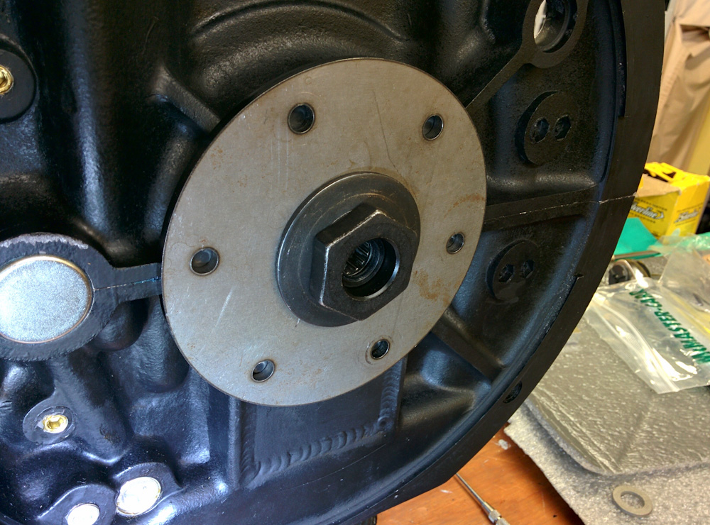
The improvised seal pulling tool, the Force One prop plate being pulled in with the gigantic flywheel nut and washer.
I had applied Hylomar to the perimeter of the seal, thinking this would help avoid leaks there. Alas, this was not a good idea. After pressing the seal in place I watched it slowly creep back out until it popped off. Clearly something with more friction was called for here. I had read somewhere that Loctite retaining compound was a good choice, so I decided to try that instead.
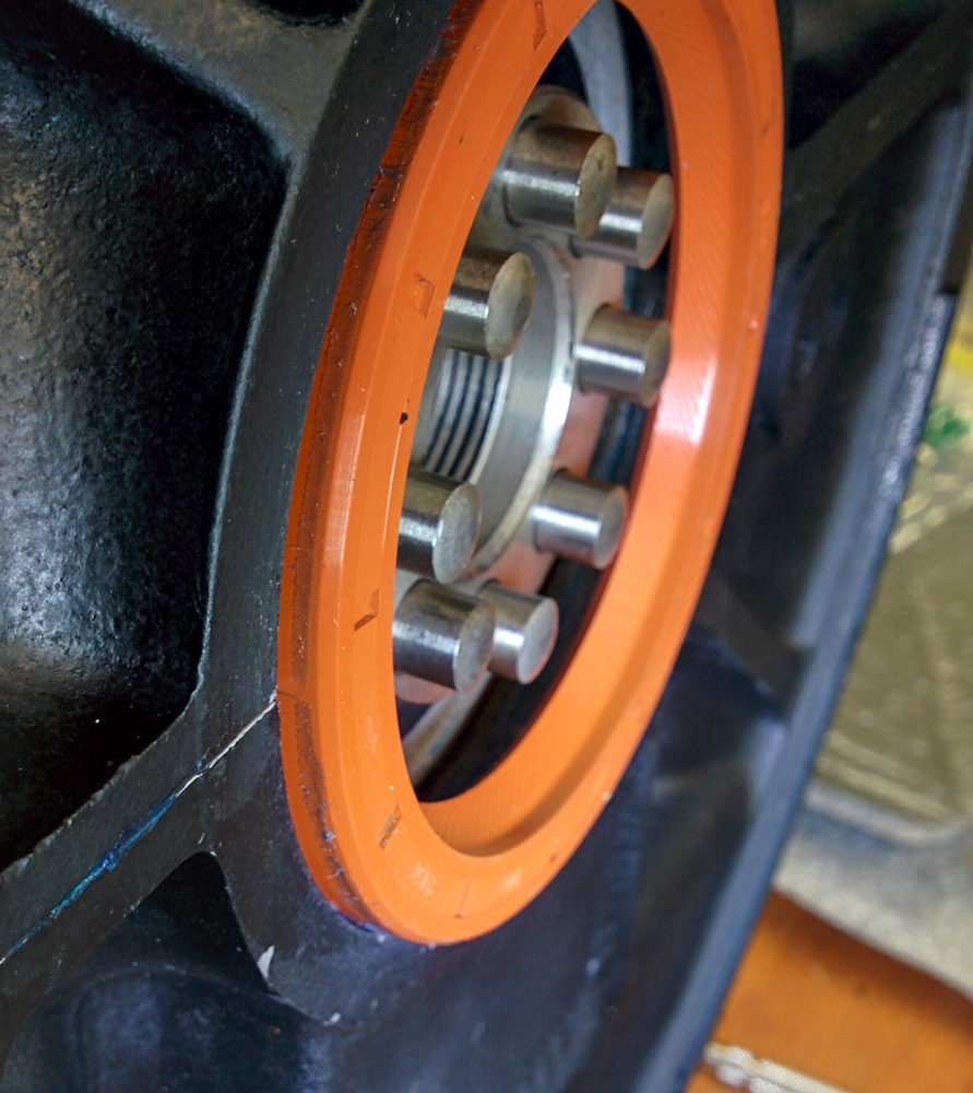
Amazingly, the thin layer of Hylomar reduced the friction between the seal and the case enough that it slowly creeped back out.
Cleaning off the Hylomar was not that easy, it’s pretty solvent-resistant. After trying acetone and ethanol without much luck, I finally pulled out the Xylene. That did the trick.
Repeating the operation, now with the retaining compound rather than the Hylomar, everything went smoothly and the seal stayed in place.
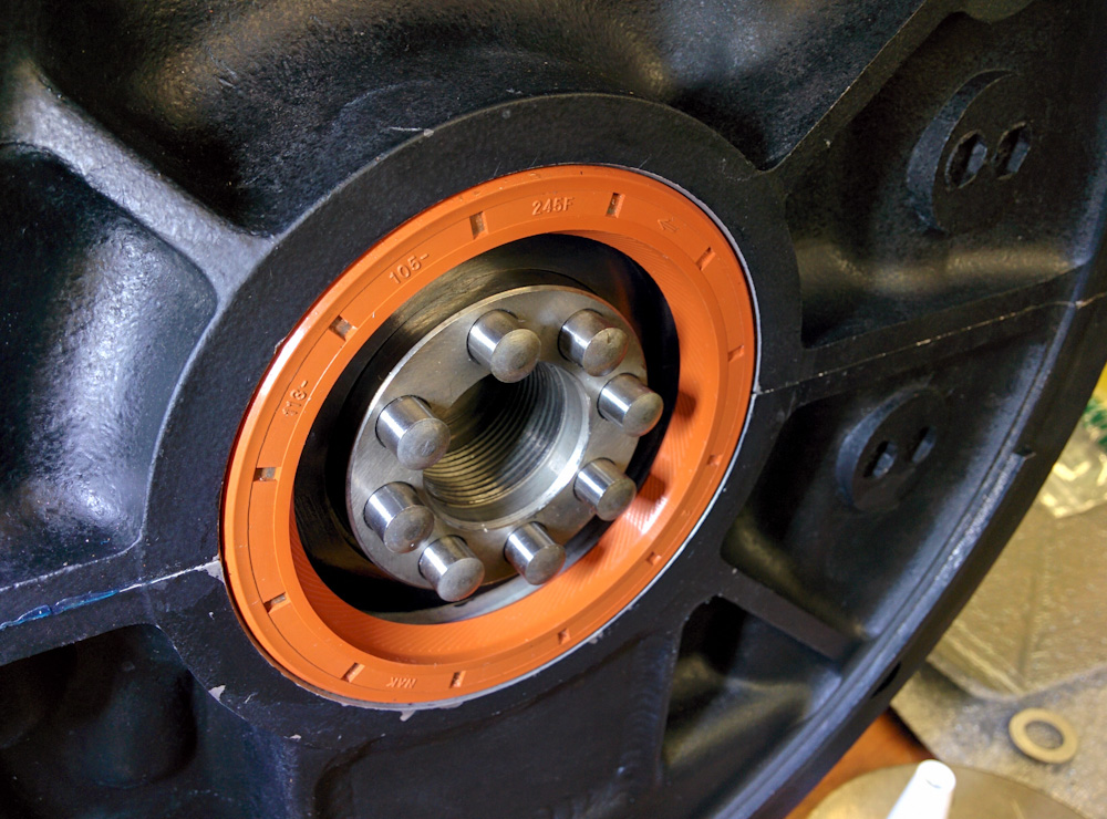
After using Loctite retaining compound instead, the seal stayed in place.
Finally, the flywheel could go on. To avoid oil leaks through the dowel pins, I applied Hylomar to the gasket that goes between the crankshaft and the flywheel. The Aerovee instructions call for silicone RTV here, but others discourage that because it builds up too thick and leads to excessive axial play.
The flywheel gasket got a thin coat of Hylomar on both sides, making sure to go on both sides of all the dowel pins.
It was finally time to tighten the gland nut. To be able to hold the crankshaft in position, I had drilled holes in a piece of wood that I bolted to the prop hub. Getting help from Kathy, who held that end of the engine down, I pulled on my largest torque wrench until the piece of wood cracked.
Digging out a long 2×4 from under the house, I quickly (the Loctite on the nut was setting up) drilled a 2″ hole in the center so I could squeeze it between the prop hub and crush plate. With 3 feet on either side, there was plenty of lever arm for Kathy to hold the engine down while resting the other end on the bench so it wouldn’t turn. I basically put all my weight on the 250 ft-lb torque wrench before we got it to click. What an ordeal.
My human counterweight holding the prop end of the crankshaft while I tighten the nut with the big-ass torque wrench to 250 ft-lb.
So there we go. The case is together. Now we can proceed to pistons, cylinders, and the heads. The next operation will be to set the deck heights.
Pingback: Engine guts 12: Setting deck height – Patrik's projects