One of the few remaining things to check was to “dial the cam”, i.e., to verify that the camshaft and crankshaft are timed correctly. In its most basic form, this is done by ensuring that the marked teeth on the gears on the crank and cam shafts are aligned, and if you were assembling a stock VW made by the factory, that might be the end of it. However, VW’s these days are collections of aftermarket parts and stackup of tolerances can lead to significant discrepancies between the actual valve timing and the design. The only way to be sure is to actually measure the lifter motion and see if it agrees with what it’s supposed to be.
This is a somewhat involved operation because you have to assemble the engine with lifters, camshaft, connecting rod, and pistons. (Technically you only need the #1 piston and lifters since if it’s right on one cylinder it’s going to be right on the others, too.) A way of reading crankshaft position is needed, so you mount a degree wheel on the crankshaft. Then you need to find the top dead center (TDC) of the piston with a dial indicator and align the degree wheel so it reads crank degrees.
Once you’re at this point, you can hook a dial indicator to the lifters and measure where the valves open and close and compare to when they are supposed to according to the cam data sheet. Bob Hoover’s blog has a pretty detailed description of this whole process, with much more detail than I’ll go into here, in case you are interested.
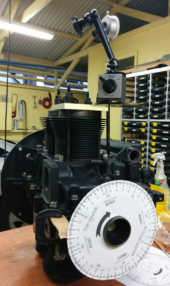
The engine set up for verifying the cam timing. The degree wheel attached to the prop hub indicates the crankshaft angle, in this case 28 degrees ATDC (After Tod Dead Center). The dial indicator is showing the position of the lifter, see the next picture.
The cam in our engine is an Eagle Performance 2234, and I found the card specifying valve open/close times in the Sonex files. However, it was kind of hard to read the writing on the card, and it did not actually specify at what lift open/close was defined at. Since the valve isn’t really either open or closed, it’s just lifted some specific amount, you need to define the amount of lift you are referencing the opening/closing to. A quick email to CB Performance gave me the answer: They use 0.015″ lift, and the spec is: “Intake Opens 33 – Intake Closes 61 – Exhaust Opens 67 – Exhaust Closes 27”. (Those all have implicit BTDC/ATDC, etc, depending on the event. See the Hoover article for the details.)
Now I knew what lift I was looking for. However, hooking up the dial indicator to the lifter turned out to be a bit complicated. The lifters are way down inside the case and the dial indicator can’t reach them. I first tried to just stack a socket on top of the lifter, which kind of worked but was very unstable. I needed something that could sit in the lifter cup and have another cup on the opposite end that the dial indicator could sit in. A pushrod is the obvious thing that can sit in the lifter, since that’s what it’s made for, but the other end is convex. After rummaging through the engine boxes I found an adjustable pushrod, and I realized I just had to make a little head for the top of it where the dial indicator could sit. Enter the JB Weld.

The adjustable pushrod and the chink of JB Weld that goes over it, with a small divot on the end that the dial indicator can sit in.
That worked like a charm, now I had very stable readings.
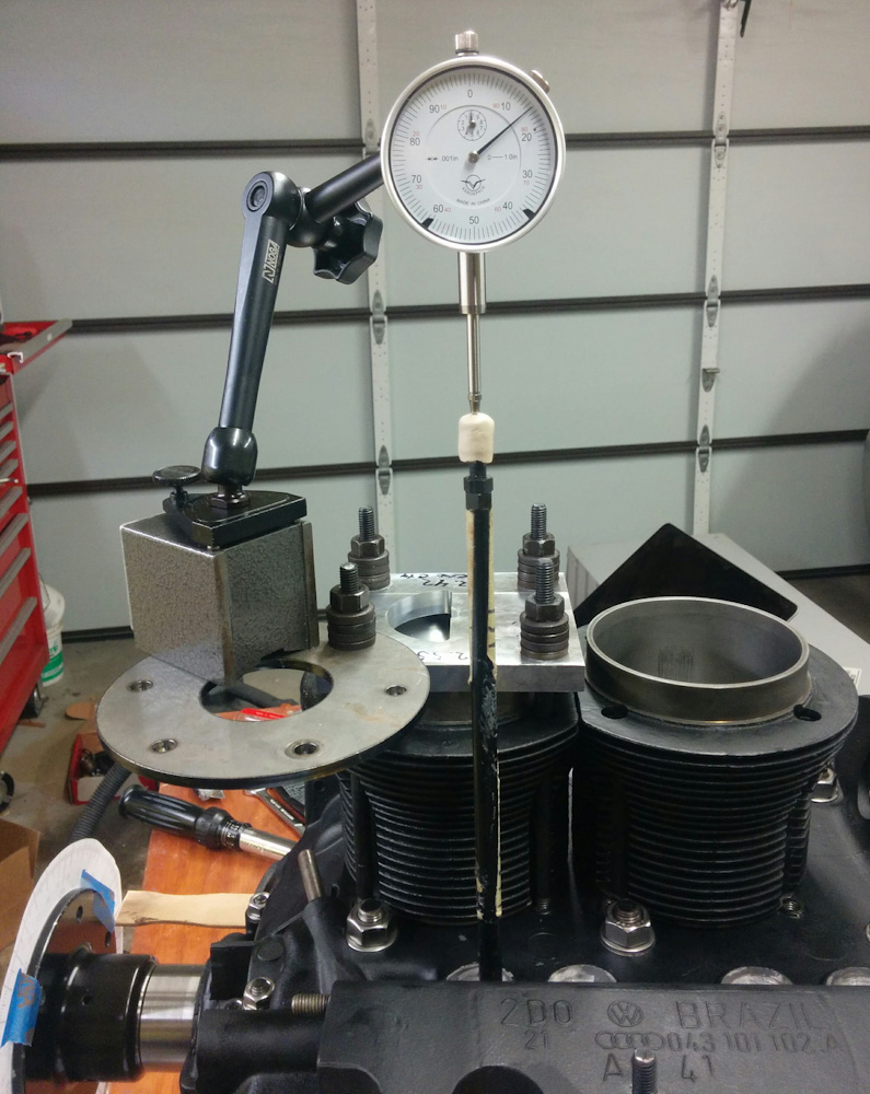
The dial indicator attached to the top of the pushrod, which in turn is sitting in the exhaust valve lifter. It’s indicating 0.015″ lift. This is the exhaust closing point. The crankshaft angle is the same as in the first picture, 28 degrees ATDC. Since the cam spec is for exhaust close to be at 27 degrees ATDC, we are within a degree.
The first measurements were intake: 35/58, exhaust: 76/24. Compared to the spec 33/61, 67/27, this indicates that the events happen 2-3 degrees early relative to their specified position. (Because the openings are “angle before” and closings are “angle after“, a larger value on the openings and a smaller value on the closings corresponds to “earlier” in the camshaft rotation.) The only exception was the exhaust opening which is off by 11 degrees. I don’t know what’s going on there, but the other three points are pretty much in agreement. 3 degrees is a pretty large error, if you manage to get a tooth off when meshing the cam gear, I think you get an offset of 6 degrees, so this was half of a tooth.
To correct this, you have to rotate the camshaft relative to its gear. There are various fancy ways of doing this but the one requiring no special parts is to simply file the bolt holes in the cam gear a bit larger. This allows you to rotate the cam a bit when bolting it to the gear, and as long as you don’t make the holes large enough to compromise the seat the bolt is bearing on, it’s fine. In this case I had to elongate the holes just under 1 mm, which I did by wrapping sand paper around a drill bit of suitable diameter and filing them out. It took a while but worked pretty well.
When I bolted the whole thing back together and re-measured, I was pleased to note that the timing was now intake: 61.5/33, exhaust 72/28, within a degree of the spec (except for the exhaust again…) Since it’s hard to reliably read anything less than a half-degree increment from the printed degree wheel, and a degree is not going to have a major impact on performance, I called that good. As for the exhaust, I don’t know. Maybe I’ll measure the other cylinders to see if the lobe on the cam is just funny.
There are now only a few more things that need to get done before the case can be closed, and then we have a bit more work to do with deck heights and rocker arm geometry. I’m seeing the light at the end of the tunnel!
Pingback: Engine guts 10: Blueprinting the oil pump – Patrik's projects