It’s been almost a year since the last NC30 post, where I had fabricated a new battery and found that the bike tune had changed and it ran poorly. The bike sat for a while since I got busy working on the Sonex, but I was forced to take it out last month since it needed the safety inspection for the registration to get renewed. Even with a fresh tank of gas, the problem remained.
I figured the problem has to be electrically related, since it showed up with the new battery. The one thing I could think was that the new battery somehow had different voltage drop to the Microsquirt, which uses the voltage to adjust for the injector dead time. If this measurement is bad it seems it could screw with the fuel/air ratio, especially at short injector times when the dead time is very important.
I had noticed that the battery voltage in the logged data has a lot of noise, and if you look at the data closely you can see the pulse width going up and down with the battery voltage measurements. If those measurements aren’t actually what the fuel injectors see, then they won’t be getting the correct dead time correction. It seemed worth looking into. If the +12V line is noisy, which isn’t unreasonable since the fuel injectors and ignition coils both draw fairly high current and are switched on and off with millisecond durations, adding a big capacitor to decouple those transient loads should improve voltage stability.
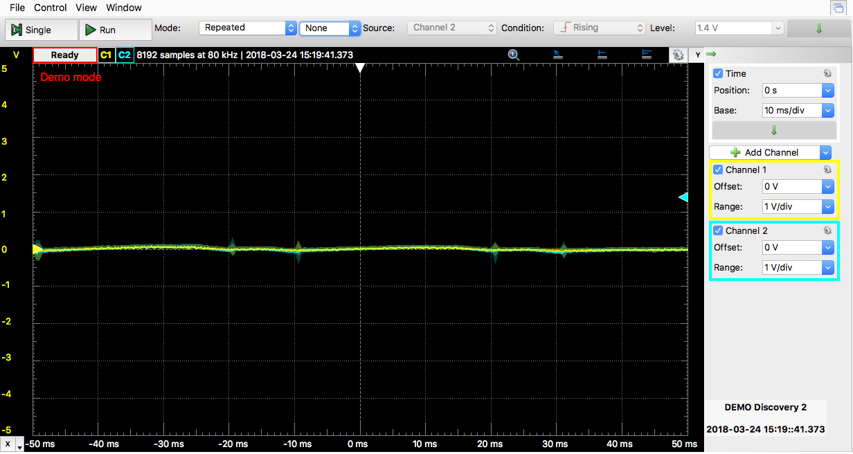
I scoped the voltage at the battery and at the Microsquirt, and got the following:
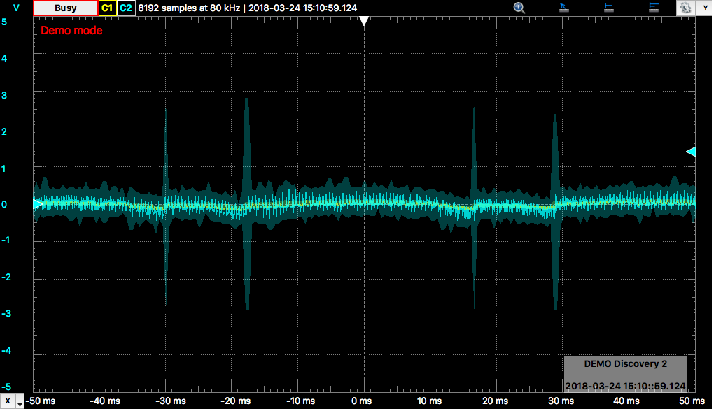
Scope plot of the voltage at the battery (yellow, almost invisible) and at the Microsquirt (blue). The four large spikes are the ignition events.
You can’t even see the yellow line, which is the battery voltage, but it is quite stable. The voltage at the Microsquirt, though, is pretty terrible. There’s about 1V of switching noise at 2000Hz and dual spikes that look suspiciously like the NC30 firing order with a 1:3 spacing. Sure enough, the frequency of those spikes in the plot above correspond to about 1300RPM, which is the engine idle frequency. Those are probably the ignition events, and the slight voltage drop before them the 5ms coil dwell when the ignition coil current ramps up. It’s not obvious where the fuel injectors trigger but the smaller spikes about out of phase might be it.
In any case, that’s a lot of noise. Given that the dead time correction is 0.14ms/V and the pulse time at idle is ~1.5ms, a 1V error on the measured voltage translates into a 10% error in the pulse width. Given that the dead time is 1.0ms, the true open time is 0.5ms so it actually is a 30% error in the amount of delivered fuel. That’s significant.
To fix this, I ordered a couple capacitors from Mouser. A ballpark estimate of what capacitance we’d need says a 1A current over 1ms should drop the voltage 0.1V. That translates to a capacitance C=Q/V = 1*0.001/0.1 = 0.01F or 10,000uF. Scanning the products I found some 25V ones that have higher capacitance, pretty low ESR (equivalent series resistance, which measures the voltage drop you get from running current into or out of the capacitor) and were reasonably priced. I picked an 82,000uF one.
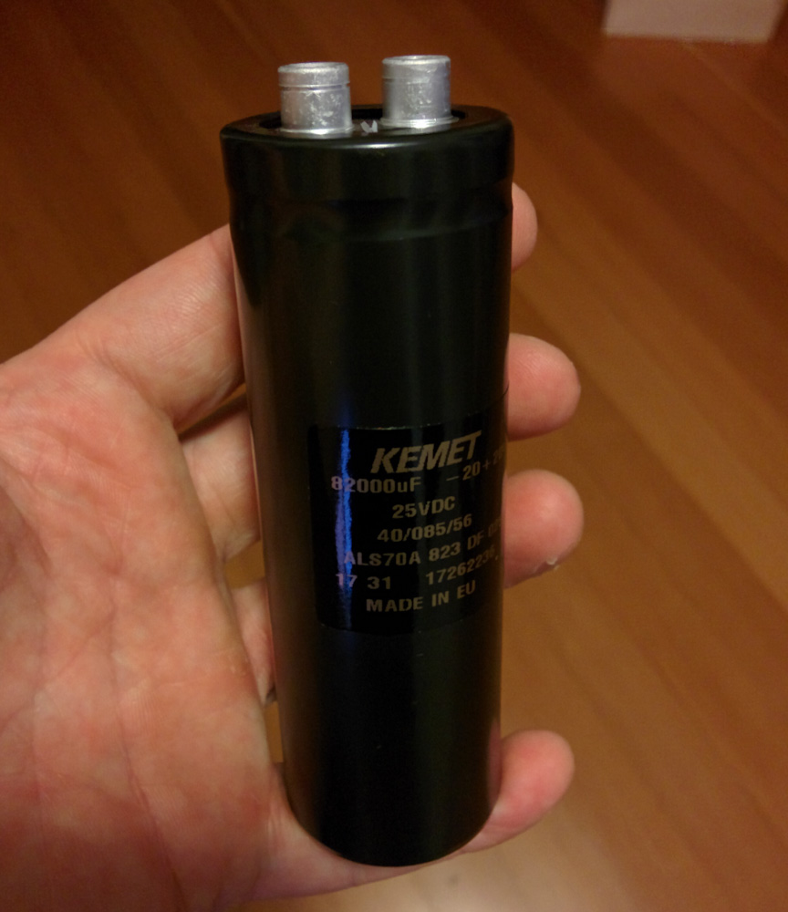
The 82,000uF, 25V Kemet capacitor I got.
Capacitors of this size are physically quite large, but this one is fairly narrow and long which makes it easier to stick it under the subframe bracket.
Connecting it was a bit of work, though. There are no exposed connections in the wiring, both the ground and power wiring is spliced and shrink tubed, so that had to come apart. To make it a bit easier in the future I decided to create a small “ground block” for the various ground connections near the Microsquirt. This includes the uS itself, the wideband controllers, the relay used by the uS to turn on the fuel pump/ignition coils, the temp gauge, the ground line going back to the battery, and now this new capacitor.
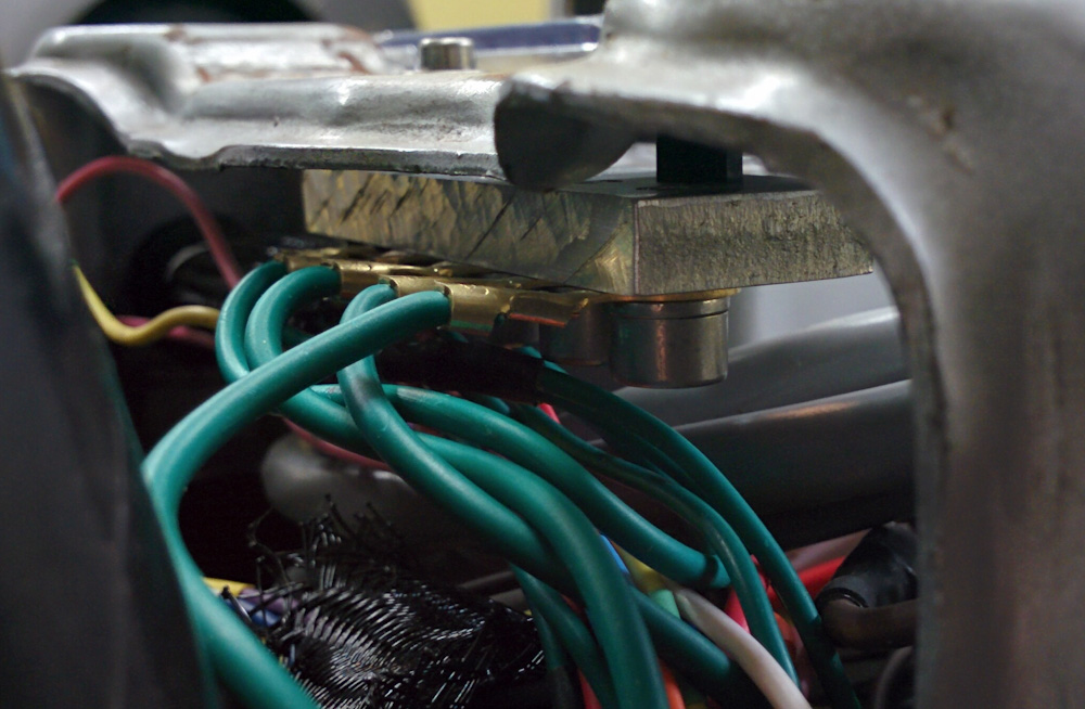
The ground block was made to avoid having to splice a bunch of ground wires, which was getting old. It’s insulated from the frame to avoid creating a ground loop.
I tapped a bunch of holes in a piece of 1/4″ thick scrap aluminum and put ring connectors on all the wires. The block itself is isolated from the frame with plastic spacers, since we don’t want to create a ground loop. It is essential to avoid picking up noise that the only connection to the frame is at a single point through the wire going back to the battery.
For the positive wire, I had to uncover the splice and solder another wire to it that I ran to the capacitor. There should be no new connections made here (I hope…)
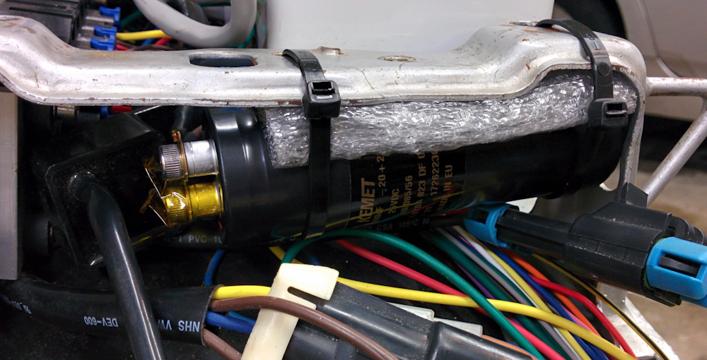
The capacitor mounted under the subframe bracket.
The connections on the capacitor are M5 screws and are quite close together. Since you really don’t want to short caps of this size, I both insulated the positive ring terminal with shrink tubing and then covered the entire terminal and screw with kapton tape. The cap is zip tied to the bottom of the subframe bracket. It’s a bit tight for the large Metri-Pack connectors that also are located there, but there should be no problem getting the seat back on.
One thing I was worried about was the inrush current. When the Microsquirt closes the relay, this capacitor will essentially be a complete short connected to the battery, and the current will basically be limited by the wire resistance. If this gets too out of hand, it might blow the 30A main fuse, but it does not seem to be a problem.
So does it work? Here’s an identical scope capture after adding the cap:
After adding the capacitor, the voltage trace is much more stable. The ignition events are still visible, but are down to maybe 0.5V.
This looks way better. The switching noise is basically gone and even the ignition events are now maybe 0.5V in amplitude compared to someting like 6V before.
Looking at the data logged by the Microsquirt, the battery voltage measurement also seems a lot less noisy:
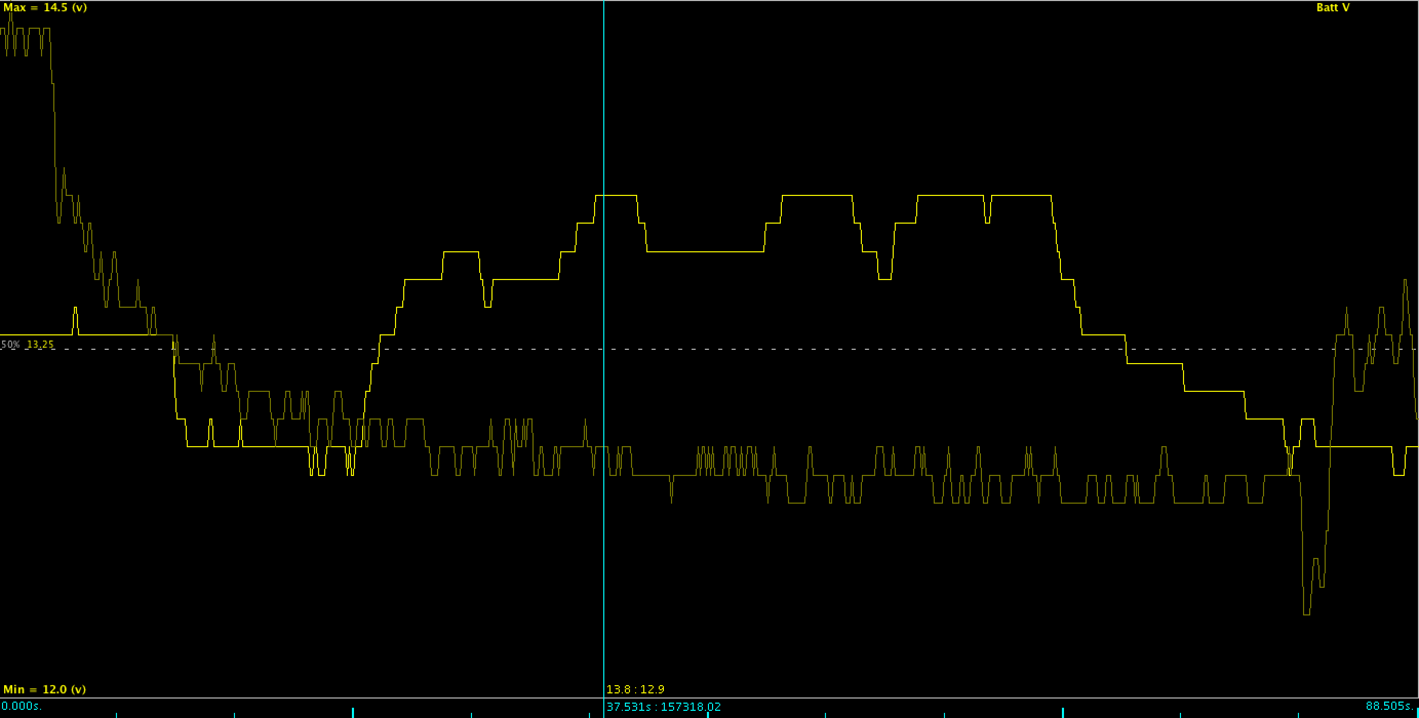
Here are two examples of the Microsquirt recorded battery voltage. The bright trace is with the capacitor, the faint one without it.
The old log, shown in the faint trace, shows significant noise in the measurements (the resolution of the measurement is 0.1V) while the new one in the bright trace is basically stable. (The large-scale voltage changes up and down are real, that’s the voltage changing when the engine is revved up from idle.)
Because the weather here has sucked badly, I haven’t gone for an actual test ride yet. It will be interesting to see if there’s less noise in the air/fuel ratio now and if the dead time voltage correction will need tweaking.
Hey there Patrik,
I’ve got an NC30, which I really enjoy as my daily ride. I’ve often toyed with the idea of doing exactly what you’ve done (converting it from carbs to fuel injection), mostly as a learning excersize, but partly to get rid of the choke (and I don’t believe it’s jetted correctly).
Have you noticed any improvements with your injected NC30 vs the carbs? Do you notice that it runs more smoothly, etc.?
I’d really appreciate any comments you have :). Cheers!
Well, I can’t comment on it honestly because I never had it tuned right with the carbs, it was always running way rich. If I had spent the ~3 years it’s taken to get this conversion done tuning the carbs I could probably have gotten it set up pretty well at this point… 😉
I don’t have it really well tuned yet, but it’s close. It’s certainly easier to start and idles better. I think it’s running better overall (although it’s hard to judge that accurately without back to back testing). I haven’t yet tried going up the mountain to 9000ft but I expect the fueling to work much better at higher altitudes than the carbs did. I’d also expect it to start better when cold but giv en the climate here I can’t really test that.
I think there’s good potential for optimizing cruise efficiency by advancing the timing at cruise throttle over what the stock ignition does, but you really need a dyno to dial that in and there are none around here.
Overall, it’s certainly been a learning experience and I’m happy with how it’s turned out, although it’s taken about six times longer than I thought it would…
Thanks for your reply :). It certainly looks like you’ve done some excellent work!
I might have a look at getting the jetting done correctly on my bike (using a lambda sensor for the front and rear bank like you have done), then take it to a dyno for a pre-EFI power level; and then do the conversion and check the post-EFI power level.
Is there any chance that I might get a copy of the CAD you did for your throttle body setup? It would save me some time and give me more confidence instead of having to pull the tank and carbs off my bike to measure them.
Kind regards,
Eric Doel
Sure. The whole intake setup is one Fusion 360 design. I’ve shared it at http://a360.co/1UyyQig, you should be able to download it from there.
The only things not included in that design are the modifications to the intake rubber boots which are at https://a360.co/2r5cgU7, and the throttle linkage which is https://a360.co/2r68WHM
Beautiful! Thanks very much for that Patrik :).
Pingback: Engine restart – Patrik's projects