After sealing up the engine guts, I had one more task to perform in the shop before the engine goes back on the plane. Based on what our bearings looked like, it was obvious that the lack of an oil filter had not worked to our advantage, to put it mildly. Deciding to add an oil filter was a no-brainer.
The trick was to figure out how to do it. Most people adding oil filters to their VW’s use a “full-flow” filter which is mounted directly after the oil pump. The oil comes out of the pump, goes out of the engine to the filter mounted somewhere, and is then routed back to where it normally would have gone without the pump. This is the same routing that our oil cooler, mounted under the engine, had.
This setup has the advantage that you always filter all oil (hence the “full-flow” part.) The drawback is the flip side of the coin, there is no way for the oil to bypass the filter when it is cold and viscous, or if the filter gets severely clogged. Since the oil pump is essentially a positive-displacement pump that will develop whatever pressure is necessary to sustain the flow determined by the speed of the gears, this can lead to very high pressures in the filter, up in the hundreds of psi, and there are instances of filters blowing open. (People have also blown out the oil cooler in the Sonex, presumably for the same reasons.)
An additional drawback of a full-flow filter setup in the Sonex is that the only reasonable place to mount the oil filter is behind the engine, but the pump is on the front. This means you have to run some very long oil lines.
An alternative is to mount the oil filter and cooler where the stock oil cooler is located. In VW’s, the oil cooler sits on top of the engine, and there’s an oil outlet and inlet on the top of the case. The oil going this route also has the option of bypassing the cooler; if the oil pressure gets too high, a spring-loaded plunger will move and allow oil to flow directly into the oil galleries, bypassing the cooler.
In stock VW’s, this functions as a rudimentary thermostat. Since pushing cold oil through the oil cooler presents requires higher pressure, this activates the plunger and lets some oil bypass the cooler. If the oil is hot, the pressure drop is lower, the plunger remains closed, and all oil will go through the cooler.
Now, this system was designed for single-grade 30W oil, not today’s multi-grade oil which have much less viscosity change with temperature. Who knows how well it actually works today, but if nothing else it will limit the pressure in the oil cooler. For this reason, I chose to move the oil cooler to this circuit, and add the oil filter there, too. If the choice is between blowing an oil filter open, which obviously results in a catastrophic loss of all engine oil in a few seconds, and only filtering part of the oil, I’m going to go with filtering part of the oil. That just sounds like the less bad option to me, especially in an aircraft engine.
This may be a bad idea, however, since adding the filter to the oil cooler circuit will further increase the pressure drop and make more oil bypass the cooler. If the pressure drop is too high, the oil might overheat. We’ll just have to see how it works. It may be necessary to run less viscous oil than the 20W-50 that Sonex recommends.
Once I decided on going this route, the problems became more practical. The oil filter needed to be mounted somewhere and an adapter for connecting to the top-mounted oil passages had to be fabricated.
The oil filter could be mounted to the firewall, but it is made of thin stainless sheet metal, and the oil filter is quite heavy, more so when it’s filled with oil. After trying out different locations on the actual airplane, my Dad and I concluded that the best place was to mount it to two of the engine mount tubes, near the top of the engine compartment. From here, we could route the AN-8 oil hoses, which are quite large, to the engine and oil cooler quite easily.
To hold the filter to the engine mount without harming the tubes, I designed a bracket that clamps around the upper tube, which takes most of the load. The lower tube just prevents the bracket from rotating and is attached with an Adel clamp. I did not want to rigidly lock the two tubes together with the bracket, since that would interfere with the load path of the engine mount.
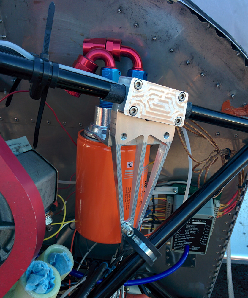
The large oil filter mounted to the custom-fabricated bracket that clamps onto the engine mount tube. The rubber-lined Adel clamp on the bottom tub just prevents the bracket from rotating around the upper one. This should securely hold the quite heavy filter. The hose connections are close to the firewall but clears it without a problem. One hose will go down to the oil cooler mounted under the engine, the other goes forward to the oil outlet on top of the engine.
The adapter to attach the oil lines to the engine needs to interface with the oil cooler attachment on the engine case, and use the same flying-saucer shaped O-rings that the stock oil cooler uses. I took a bunch of measurements on the engine and drew it up in Fusion 360, but after fabricating it I discovered that I’d made a mistake and nothing lined up. Frustrating to say the least, especially since it’s a fairly complicated milling job.
I made the first attempt back in November, and it wasn’t until this weekend that I managed to find time for the second try. This time I had double- and triple-measured, and even 3d-printed a test piece to make sure everything would fit.
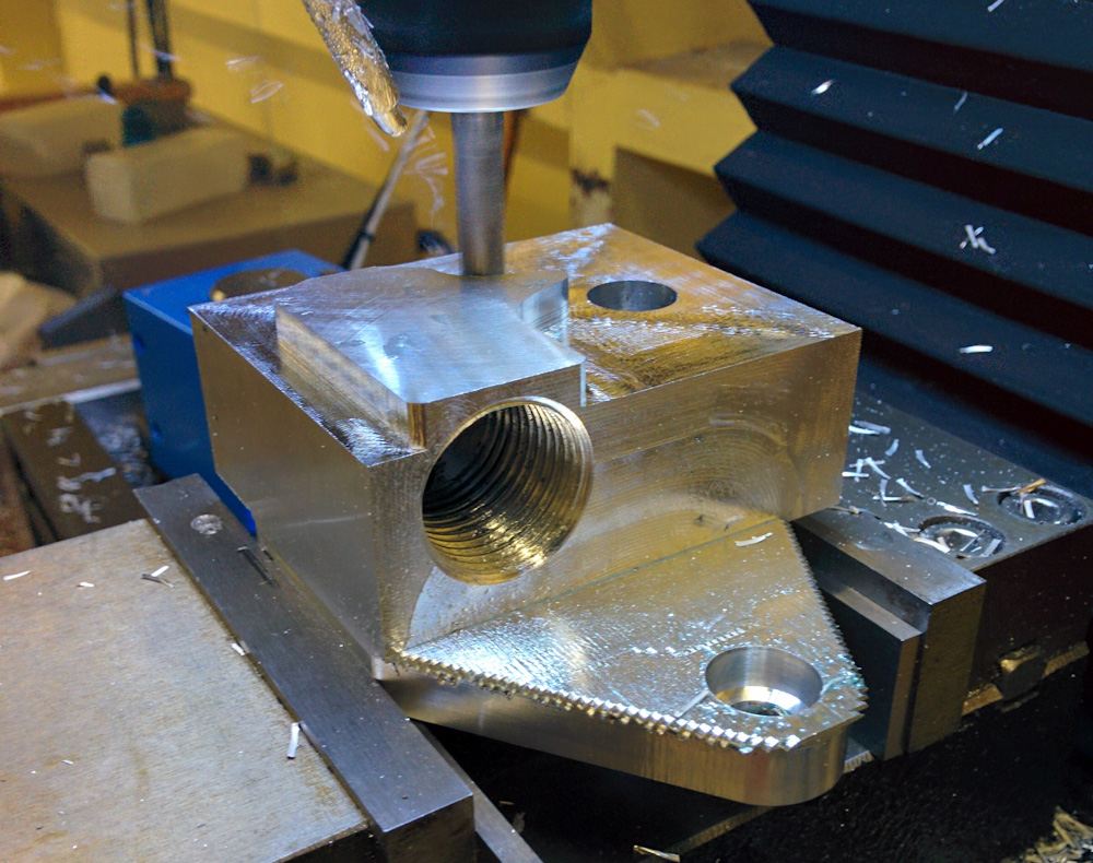
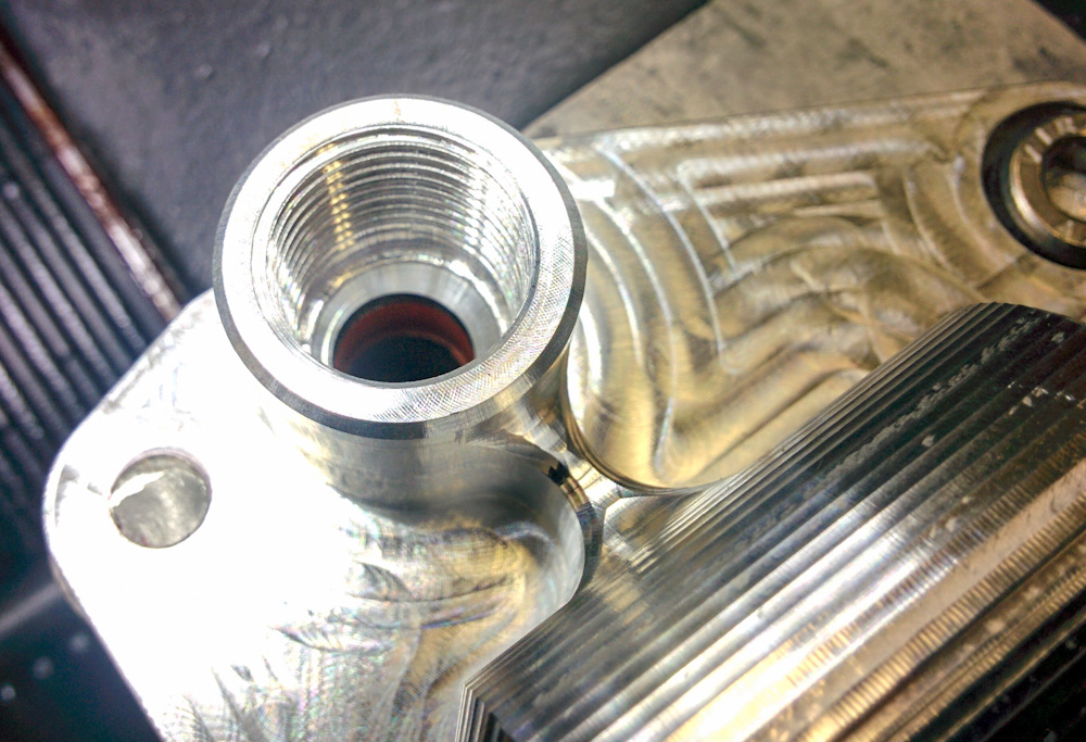
Working on the oil adapter. This is the fourth and final setup, the 1/2″ NPT oil outlet has already been tapped.
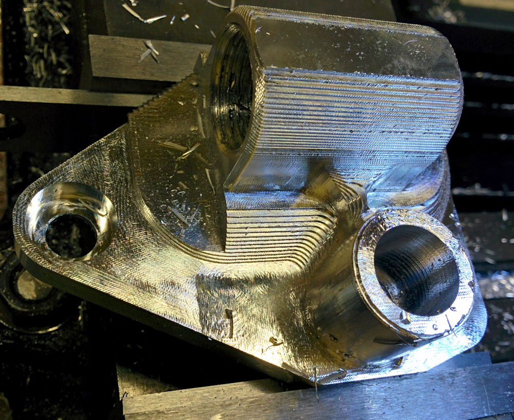
After rough-clearing the last setup, it looked like this. The vertical 3/8″ hole is the oil return line.
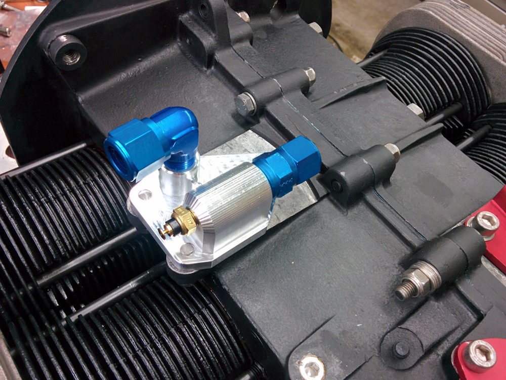
The finished adapter mounted on the engine. The outlet goes to the right, where the line will bend around and go back to the filter. The return line will come from the oil cooler and back from the left side of the picture. The outlet also has a temperature sensor, which should provide a more accurate oil temperature than the old sensor which was located in the corner of the oil sump.
The oil lines will be made of -8 AN aluminum tubing from the adapter to the baffles at the back of the engine, where they will go through the baffle and then transition to hoses. Since the engine is mounted on flexible rubber mounts, you can’t run a hard line between parts mounted on the engine and parts mounted elsewhere.
In this picture, with the return elbow removed, you can barely see the orange O-ring that’s sitting between the adapter and the engine. I hope the O-ring has enough squish to not leak oil. If it turns out more squish is needed, we can just take some material off the bottom of the adapter.
With this part done, my garage work on the engine is officially over. That was 4.5 months and a lot more work than I anticipated when we took it off. But I hope it’ll be worth it.
What work remains replacing all the wiring and accessories, needs to be done in situ with the engine back on the plane. So the next operation is to haul the engine back down to the airport and mount it on the plane.
Do you have any additional pictures (specifically possibly a fluid routing schematic)? I am desperately looking for a “real” oil filter solution for my AeroVee, but I have the top mounted oil cooler, so I’m not sure the solution you’ve developed would work, at least not without some modification. I was hoping to see how you managed oil flow to hopefully avoid any explosive oil filters / cooler!