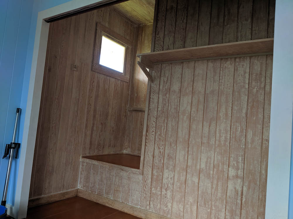
In the last post, I talked about the painting of the room. However, since we hustled to get the room habitable, we skipped the closets. Before the Swedish grandparents arrived for their visit this year, we wanted to get that done.
As you may guess by now, this entailed first stripping a bunch of lead paint.
The closets have been stripped. That’s the most painful part of the job done.
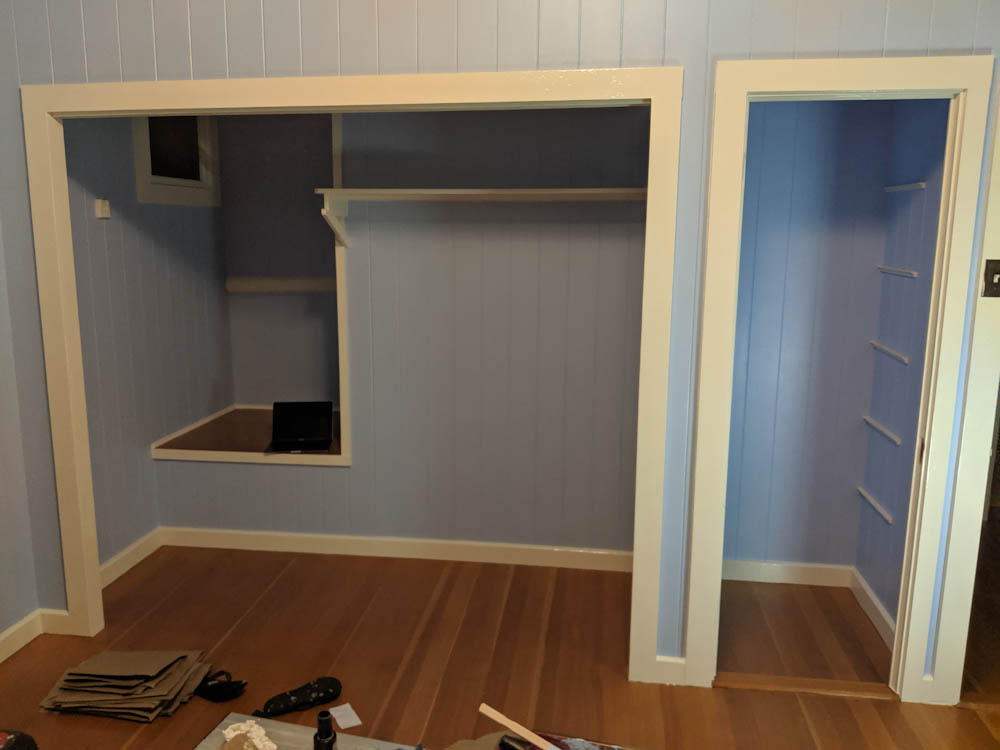
After stripping, it was time for 2 coats of primer and 2 coats of top coat, Bermuda Blue for the walls and Royal White for the trim.
Closets are done and the room is now complete.
We completed the closet well in time for the grandparents’ arrival and the “library/guest room” is now complete… with the exception of the closet doors, of course. There are imperfections, obviously, but overall we’re very happy with how it came out.
As usual the grandparents visit was occasion for getting some more home improvement done. More on that in the next post (which hopefully won’t take months.)
Wow, posting’s really dropped off this year. Hard to get the time to do stuff, even harder to then actually write something about it.
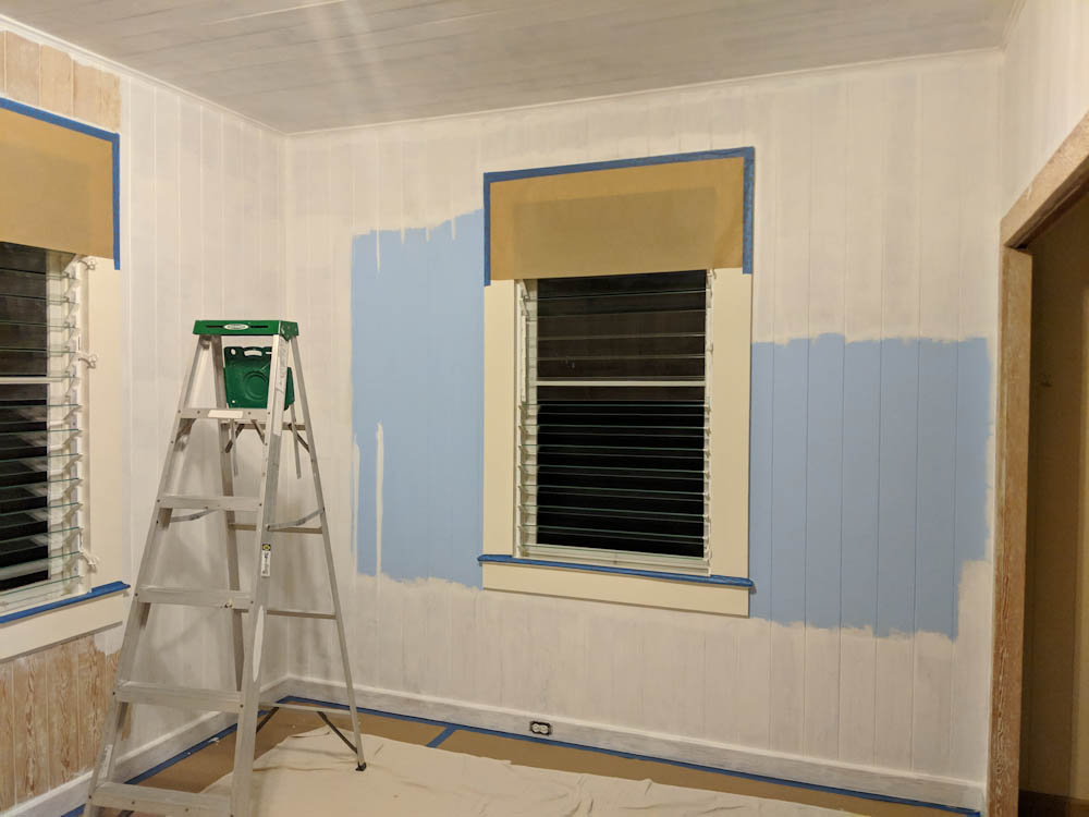
When we ended the last post, I was going to show you the room painting project that we continued with after replacing the windows. The first, and most painful task, as always, was to strip all the lead paint. If you look back to the previous post you know we already went through this with the windows. The wall and ceiling is a lot more surface area but it’s actually a lot quicker to do flat areas and not have to worry about corners and edges, so it took us a few days.
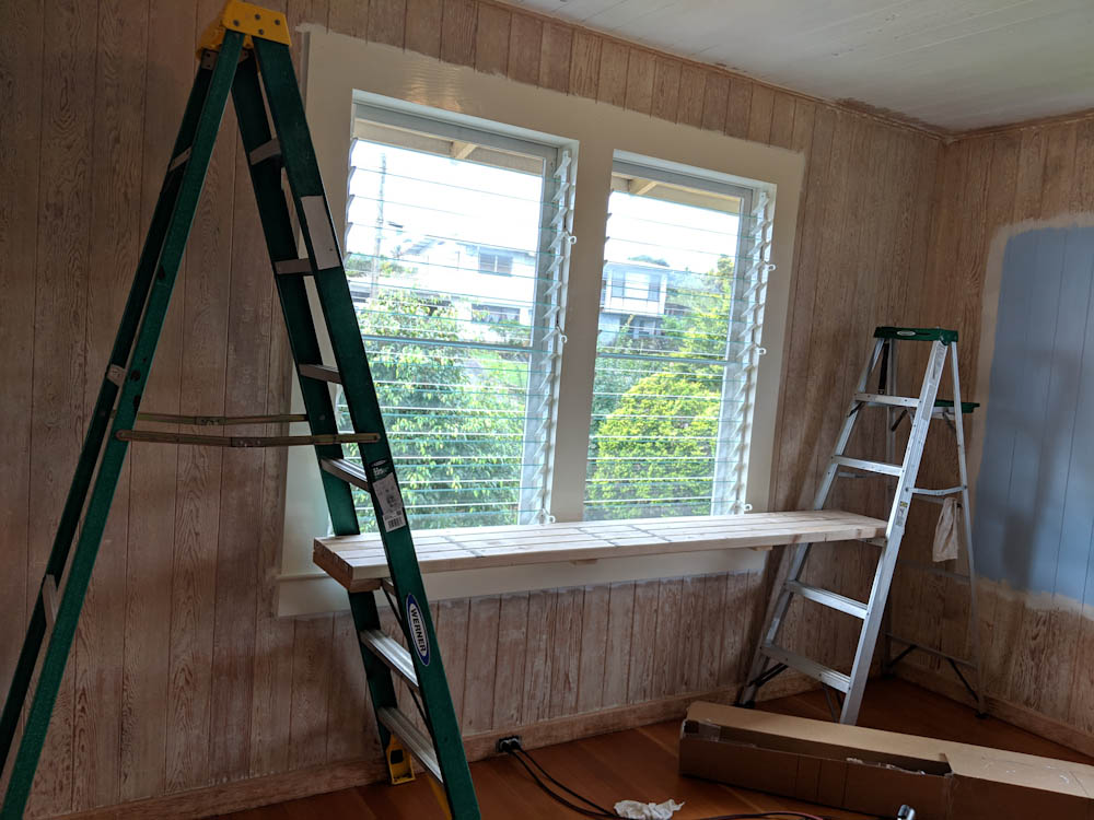
To be able to work the ceiling efficiently, we constructed a platform from a few 2x4s that we could span between the ladders.
To get the ceiling done without breaking our necks we made a platform hanging between the two step ladders, and we used the Speedheater movable arm attached to a tall metal pole on wheels. That way you don’t have to hold it up, you just move it from place to place and scrape the areas you’ve heated.
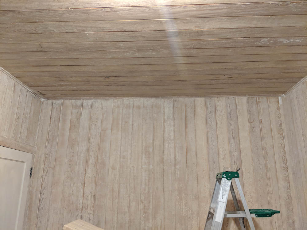
The walls and ceiling have been stripped, ready for priming.
Once all the old paint was off, we repaired some termite damage and filled every seam between the planks with sealant to have an elastic seal there instead of a gaping hole where the planks move.
In general, there was not a lot of termite damage found, but this area of the ceiling was pretty bad.
To make sure we got a uniform, well-primed base, we elected to go with two coats of the Eco primer/undercoat. We rolled it on, but they recommend a foam roller for this and that obviously won’t get paint into the grooves between the planks, so before rolling we had to go through and hand-fill the grooves with a brush. This easily made it take more than twice the time compared to if we’d just had a big flat area.
The first coat of primer is on. It gets absorbed a bit into the wood so to get a uniform base, and more durable paint, we did two coats of primer.
With the second coat of primer, the base is nice and uniform. Here we’ve started painting the trim along the ceiling with the Royal White flat paint we’re going to use for the ceiling.
Once everything was primed, we rolled the Eurolux ceiling paint. This is the same Royal White color we use on the trim for windows etc, except it’s flat instead of shiny.
Because the Eurolux acrylic paint dries quite quickly, it was difficult to not have the paint dry between filling all the plank joints and doing the edges, etc. It helped to do this as early as possible in the morning so it wasn’t so warm.
It was really difficult to edge and roll the main areas without the paint beginning to dry, so we did the corners and top/bottom early….
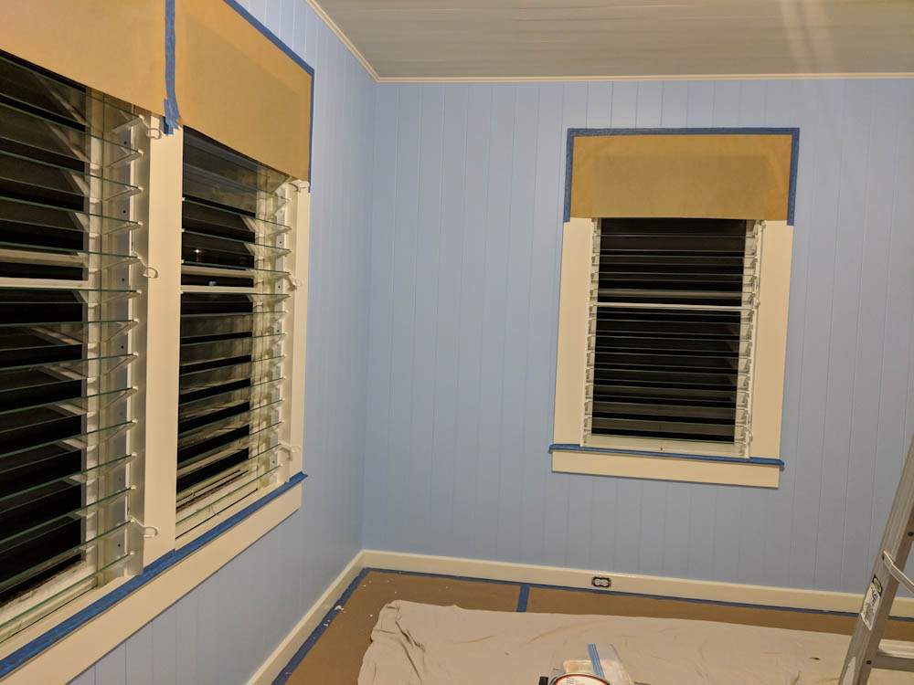
With the ceiling done, we proceeded to the “Bermuda Blue” wall paint. This was applied in two coats, rolled in the same way as the ceiling.
After the first coat of blue you can start to see what it’s going to look like.
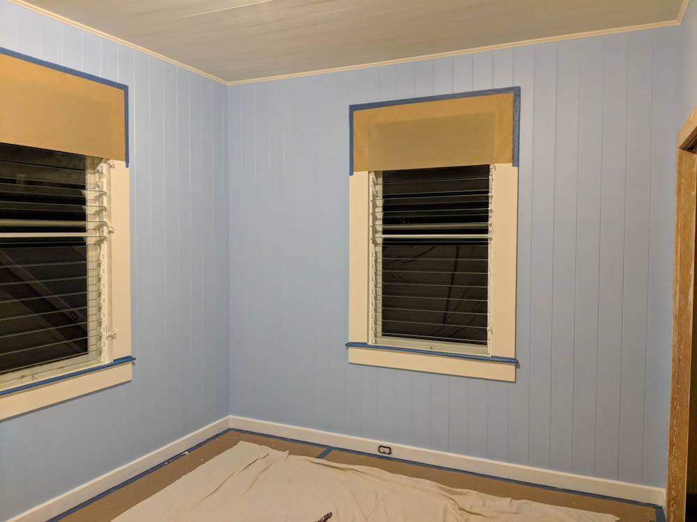
Two coats of blue done. I think at this stage we’d also done the first of the two coats along the baseboards.
Finally, with two coats of blue done, it was time to crawl along the baseboards and paint them using the same shiny Royal White paint that’s used on the window trim.
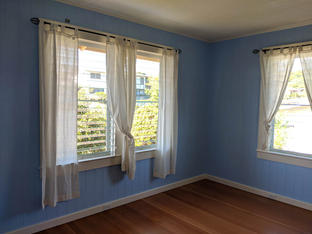
The final product, with the room back in usable shape.
The room got done right at the deadline, which was the inlaws arriving. They did have to sleep in the office one night while I did the final coat on the baseboards, but that seems like a small price to pay to get such a nice guest room! We’re really happy with how it came out. Maybe we should move out of the master bedroom and in here now just to experience it!
So there’s been a 5-month hiatus on posting, but things have been happening. I’ll try to catch up.
During November, the grandparents came for their usual month-long Hawaii visit, and the task my Dad and I decided to tackle this year was to replace the old counterweighted “sash” sliding windows in the two rooms in the main house. The real objective was to remove the lead-based paint on them, since they are high-wear surfaces and the paint had started to crack and peel. The paint in the “library” is especially deteriorated, not just on the windows; it’s peeling all over the walls and the ceiling. But the windows were a start.
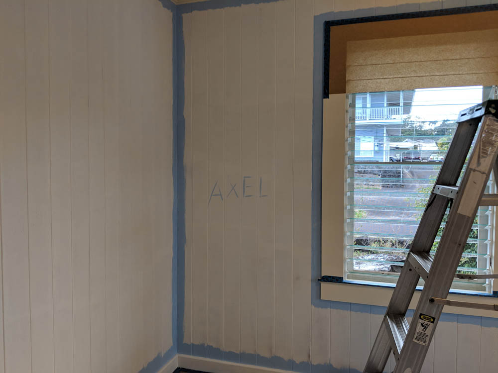
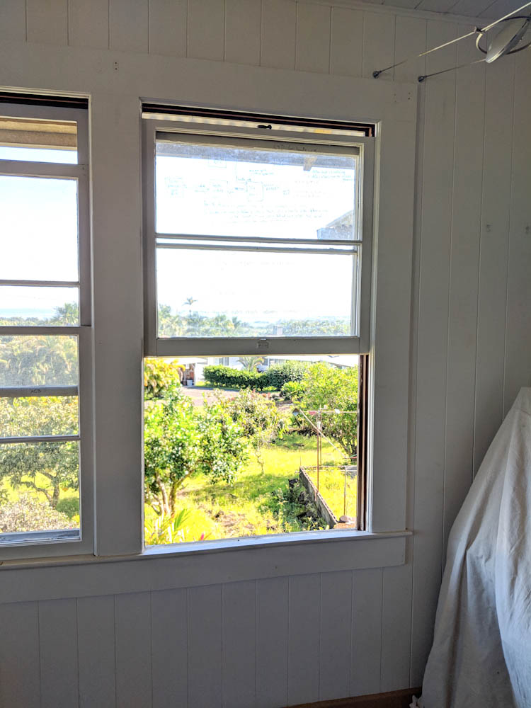
This is one of the original sliding windows (also used as a whiteboard…)
Rather than attempt to strip the paint from the existing windows, we decided it was better to switch them out for jalousie windows. Literally every other window in the house use jalousies and they are superior for the amount of airflow they provide. The only issue with our existing ones are that they are aluminum and have pretty severe corrosion. For that reason we chose to go with Palmair windows made by Breezeway. These use vinyl, powder-coated aluminum, and stainless steel, and the mechanisms are protected so they’re not exposed directly to the elements. They also seal much better than the old metal ones that don’t really make a tight seal between the slats.
The Palmair windows are also reasonably priced, at least compared to the other vinyl alternative one of the local window dealers had, which were almost 3x as expensive. We just had to drive over to Lowe’s in Kona to get them.
Getting the old windows out was an interesting exercise. To remove the sliding windows out of the frame, you had to break off the nailed-in-place wooden trim that held the windows in. Then you had to cut the ropes to the counterweights, tie a knot in them so the counterweights didn’t drop to the bottom of the window, and then take the inner window out. The outer window was then held in place with rectangular wooden rods that were fitted in a slot in the window frame. With the windows removed, you could open an access panel in the side of the window frame so you could reach in and grab the counterweight, cut the knot in the rope, and pull the weight out. These weights were large bullet-like chunks of cast iron, when you slid the window up and down they would clang against each other like some heavy-duty wind chime.
First step was to take the windows out. This required taking the inner window trim out at which point the inner window can be removed, the center trim taken out, and then the outer window taken out. Note the stumps of rope which are still holding the counterweights inside the window frames.
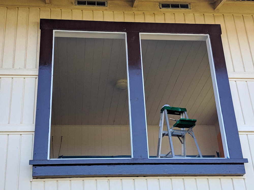
After removing the counterweights and putting the access panels back, we were left with a window frame with a slot all around the perimeter and holes where the counterweight pulleys had been. These needed to be covered, so we fabricated plywood sheets for the sides and top of the window frames.
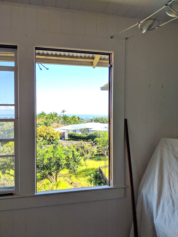
Both windows are out. We also removed one of the planks from the window frame to see what it looked like inside. There was what I assume is 70 years of dust on the bottom of those cavities, but no termite damage. The sides of the window frames have slots for the trim and holes for the counterweight pulleys. These were covered with thin sheets of plywood.
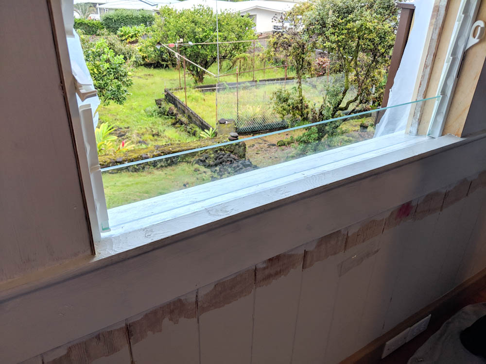
With the side plywood panels mounted, we temporarily mounted the new windows to make sure they would fit and to figure out exactly where to mount the frames. To get the bottom of the windows to seal, we’d also need to add a piece to extend the bottom of the inside window sill outward so we could add weatherstripping against the inside of the bottom of the glass.
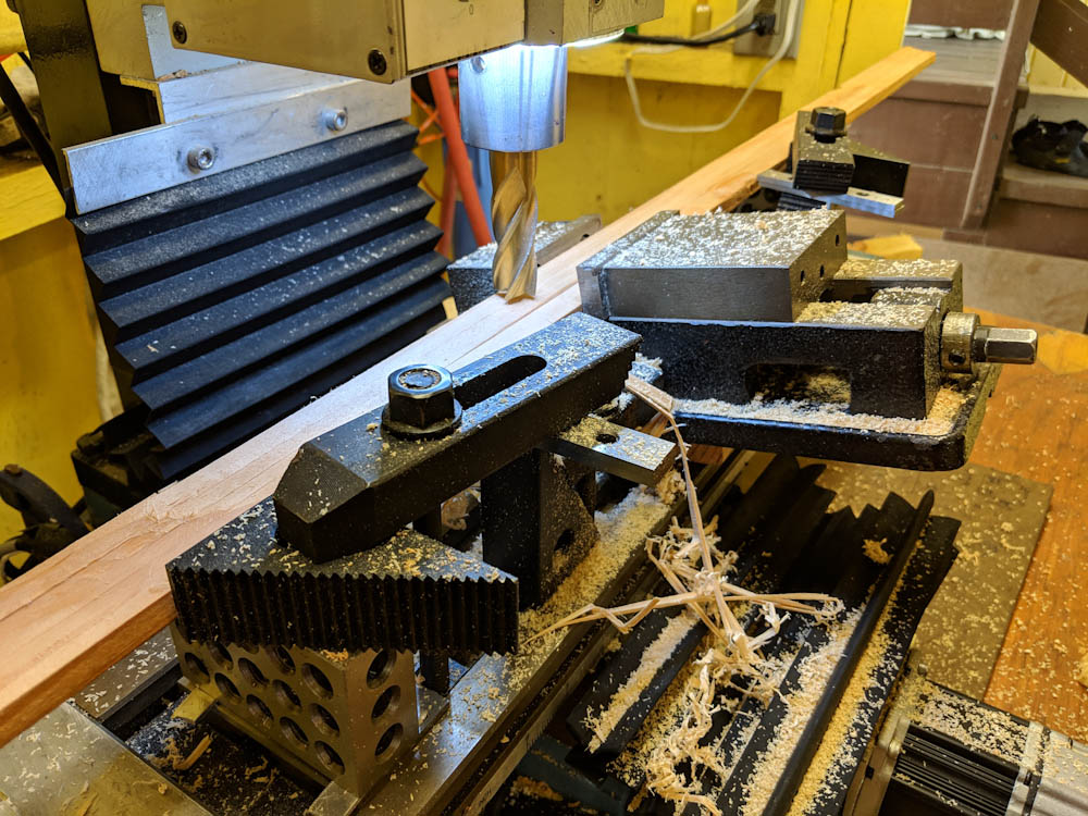
In addition, we needed to fabricate extensions to the inside window sill so it would go all the way to the glass. Because this would have sit on top of the outside portion of the window sill, which is inclined by about 13 degrees, it had to be made in a trapezoidal shape to lie against the tilted bottom and line up with the horizontal top of the inside of the window sill. Making 7 of these pieces with the correct angle and thickness by hand seemed like an iffy prospect, so we tilted the vise in the mini mill and used it as a “guide” so we could slide the pieces through the mill and have it take off the appropriate amount of material.
The window sill needs to be widened since the new windows set further out. The existing base of the windows is inclined about 13 degrees, so the trim pieces need to be shaped like a right trapezoid. The mini mill was set up to be able to make the 7 pieces in a reproducible way.
The outsides of some of the window frames were also in such bad shape that rather than try to get the paint off and make the wood look decent, we replaced them. Stripping the outside paint was quite a chore, it’s quite resistant to the infrared heater and you have to heat a lot to get it to soften. The wood is also quite rough so the scraper can’t get the entire paint layer off like it could on the inside where the old paint came off easily.
Having finished the woodwork, we needed to paint the windows, inside and out, before mounting the windows. This seemed like it should be quick, but took quite a while. The inside window frame was first painted with Brushing Putty (which I’ve talked about before) to mask some of the very coarse grain in the wood. This needs 24+h of drying, then sanding. Then the oil primer, which needs another 24+h of drying, and then two coats of the Eco “waterborne alkyd” paint. Since the outside is brown and the inside white, you also could only do one side at a time since otherwise you’d smear the paints into each other.
Before mounting the windows, the window frames were treated with Brushing Putty, sanded, and painted with the same Eco Brilliant Royal White paint that is used in the kitchen. With all the coats and drying time, this actually took over a week. (This also explains why there weren’t any blog posts at this time since the thing under the big cloth in the corner on the right is my computer…)
The outside of all windows are painted Tudor Brown. We’ve previously used a Benjamin Moore glossy latex paint for this, but we’ve not been happy with it as it remains sticky for a very long time and does not seem to hold up well to the elements. Instead, we got a satin version of the same Eco paint we’re using for the internal white trim, matched to the BM Tudor Brown tint. This is an alkyd paid so dries to a hard, weather resistant surface. Hopefully this will hold up better outside.
Since my parents were staying in the other room, we couldn’t get started there until we were done painting and had the windows mounted. This took quite a while longer than anticipated so by the time we could get started on the other room, we only had one week left until my parents went back home to Sweden. This was enough to get the wood work done, but not the painting.
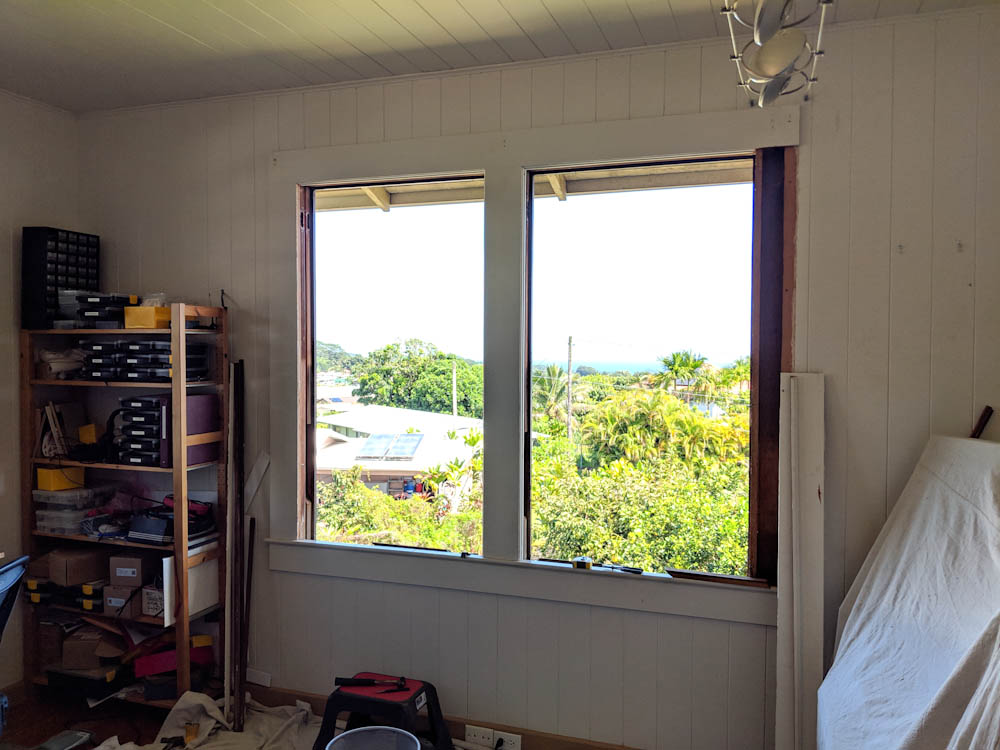
After finishing the 4 windows in the office, we moved on to the 3 windows in the library. As is evident in this picture, the paint in this room is in really bad shape, flaking and molded. More on that later.
Since the paint on the walls and ceiling was in such bad shape in this room, peeling and full of mold stains, we decided that this was a good opportunity to repaint the entire room instead of just doing the windows. So we started stripping the walls. This actually didn’t take too long, with the Speedheater you can cover about 1m^2 per hour, when you don’t have to deal with trim and corners and stuff. The windows went a lot slower.
Holding the Speedheater gets very tiresome after a while, you basically hold it in one hand and strip with the other which is hard on your shoulders and wrists. As we discovered how hard this job would be, we ordered the “arm” that holds it so you only have to reposition it and not hold the weight. However, it didn’t arrive until the job was mostly done. I’ll make a separate post about the repainting of the room.
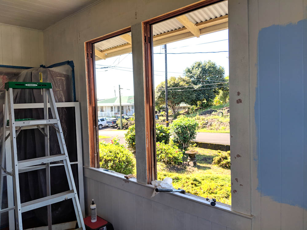
Nearing the end, the windows in the library are painted and the windows are ready to be put in. As you can see, we’ve also started stripping off all the wall paint. More on that later.
Finally, the windows can be mounted, here two are done and I’m just about to start working on the third. The only thing remaining is to cover the small space between the top glass and the top of the frame. This will have to be done similarly to on the bottom, but is not urgent since only in a major hurricane would the wind blow hard enough that rain would hit the window that high up under the eaves.
In the end, I think this was a major upgrade. The old windows weren’t just peeling, when the wind was blowing they also would shake in their mounts, giving off a rattling sound that isn’t so nice if you’re trying to sleep there. The jalousie windows will give a lot more airflow (although we haven’t had occasion to need that since it’s been “really cold” here. Cold for Hawaii, that is.) The new paint also looks really nice. I can’t even imagine how nice the whole house will look when we’ve repainted all the trim, door frames, baseboards, etc with this paint. So we’re really pleased with the new windows. Stand by for the next post about painting the room.
It’s been two years since the last time progress was made on the kitchen. We still didn’t have any cabinet doors, and recent developments have caused this to be a more pressing matter…
Here’s the recent motivation for getting doors on the cabinets. At least the lower ones.
We had focused on the lower cabinet doors the last time we made a push, and gotten to the point that they were all primed. Over the past 18 months I did the final sanding, so they were bascically all ready to be painted. It’s kind of silly they’ve been sitting so long, but otherthings came in between.
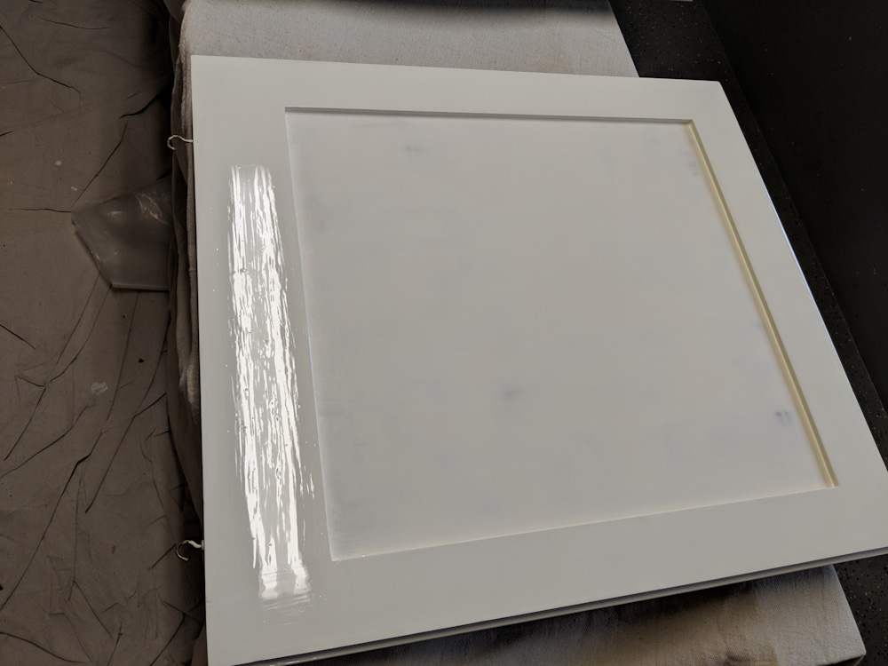
In any case, it was now time for the final push. If you need to remind yourself what the cabinet doors looked like when we started, you can go back to the original post. First, there are two coats of the white Eco Brilliant on the frame. This is the same paint we used for the rest of the kitchen framing, super shiny but that also means you can see every little imperfection.
The cabinets with Eco Brilliant on the frame. Every little dust speck and imperfection shows up here, so it’s pretty humbling.
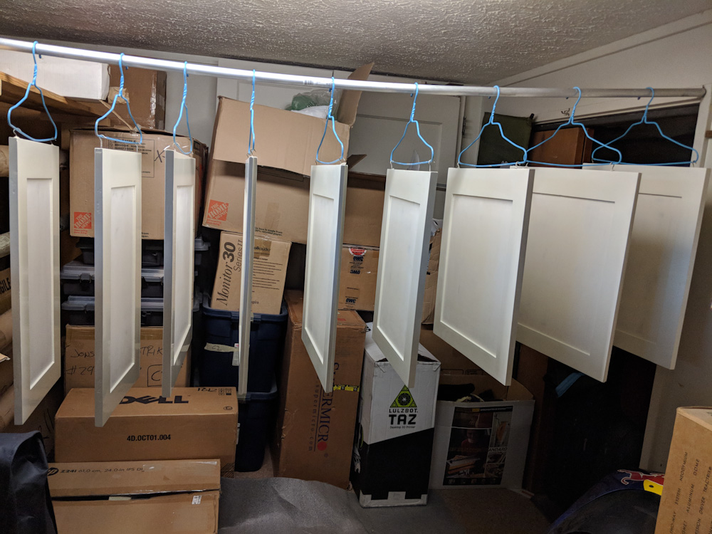
The Eco paint is really nice to work with, dries pretty quickly and has no odor. Once the door is painted, it gets to set up while horizontal, and once it won’t run the doors are hung up to minimize the amount of dust landing on them.
The doors were left to dry in the dehumidified room (but with the dehumidifier off to not make them shrink too much.)
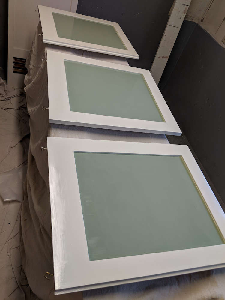
With the frames done, the next step was the green Eurolux paint in the center (not sure what the term is in English, in Swedish it’s called the “dörrspegel”, door mirror.) This is a matte paint, so is a little more forgiving when it comes to the surface. On the other hand, you need a steady hand to cut the edge against the white so it actually took quite a while to paint.
Painting the green centers of the doors.
With two coats of those done, the painting stage was over. Next: drilling holes for the hardware.
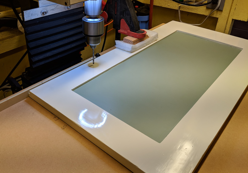
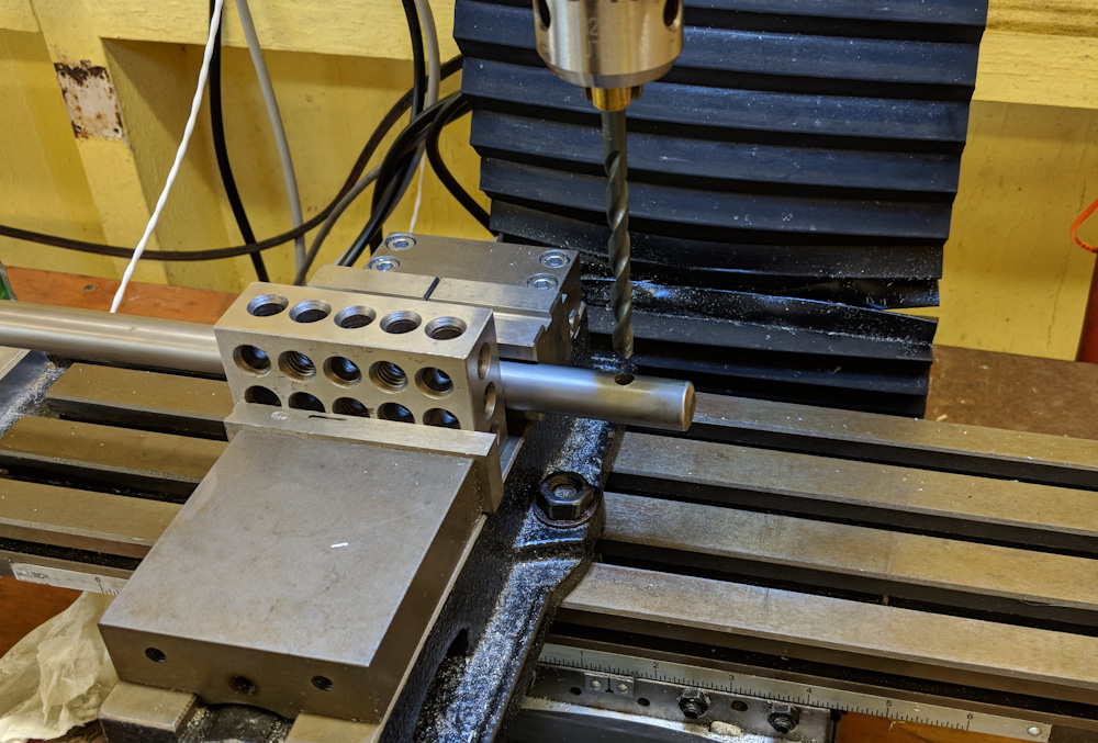
Back when we trial did the first door, my Dad and I made a fixture out of a large MDF board that mounted to the table of the mini mill. I cleaned that out and reminded myself what the measurements were. It might be overkill doing this on the mill, but it meant that the holes would have the correct spacing and that the handles and hinges would just fit right. Once I had the procedure down, it probably didn’t take longer than doing it by hand since then you have to be very careful.
The first step was to drill the two holes for the handles, 128mm apart.
First step was to drill the two 4mm holes for the handles. By clamping the door against the guide, aligned with the mark, the position was reproducible to reasonable accuracy. What’s really important is the relative location of the holes since that determines whether it will fit or not.
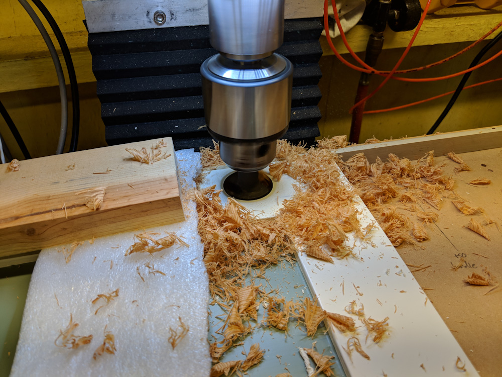
The hinges used a 35mm boring bit to cut the hole for the “cup”, and two small pilot holes for the screws that hold them in place.
Boring the hole for the 35mm hinge cup. This needs to be at least 13mm deep, and the doors are 18-19mm thick. It’s not super close, but there’s not a whole lot of margin.
I did all this by hand-typing commands in to the mill, and there were only two screwups. I mistyped the spacing for the hinge screws by 1mm in one instance, which wasn’t so bad. The more serious one happened when I typed a “z” instead of an “x” and crashed the drill chuck into one of the doors. Luckily it was the inside, since I was drilling the hinges, but the new servo had enough torque to push the 2.5mm drill clean through the door before it broke off. The tip did poke through the front, but only barely, and it’s the lower hinge down by the floor, so it’s not very visible. I’d worried about doing something like this, but considering what could have happened (like drilling a 35mm hole straight through the door) it’s not so bad.
In contrast to the holes in the doors, the holes for the hinge clips in the frames had to be hand marked and pilot drilled, which took a while. I completed this without any screwups, although in one case I managed to precisely hit the head of a screw that we had used when adding the cover pieces around the range…
Mounting the hinge plates in the door frame. This was a manual measure-and-drill procedure.
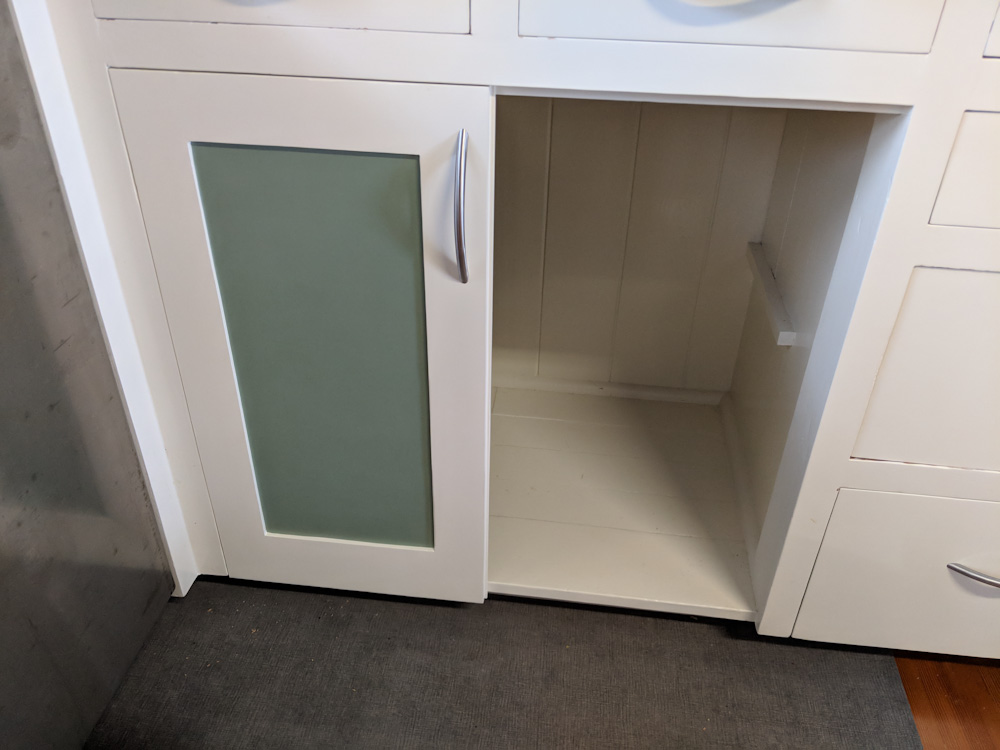
The first door is in place, eight to go.
The hinges have a bit of adjustability in every dimension (in/out, up/down, left/right) so it’s not a disaster if the position of the hinge plate varies by a mm.
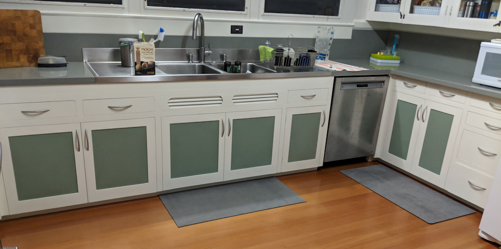
It took basically two full days to do all the drilling and mounting, but now all the under-counter cabinets have doors!
All the under-counter cabinets now have doors!
There’s definitely some variations in the gaps, so you can tell that it’s all hand-made, but it looks pretty good! An unexpected result is also that the kitchen became noticeably brighter compared to having those black holes under the counters.
So what’s next? We’ll savor the completion of this long-standing project for a few days, but there’s more to do. We could start working on the above-counter cabinets (not just the doors, but the cabinets themselves still need to have the lead paint stripped, too) and have those done in another … 4 years? I think the more pressing ones, however, are the few full-height cabinets to the left of the counters. One of those hold all the cookware, and having Axel pull down the 18″ cast iron skillet on his head would probably not be good.
After fixing the main wheels, there was also some things to attend to at the back. We’ve had a replacement for the ridiculously dinky tailwheel since before I became a co-owner but never mounted it. Since we were doing wheel work anyway, we decided now was the time.
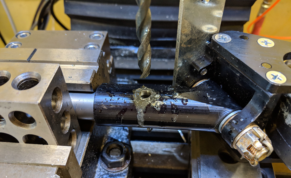
Replacing the tailwheel looked simple until we realized that it did not have a hole for the bolt that holds it to the titanium rod that makes up the tailwheel spring. Drilling this hole so that it matched the hole in the rod was not going to happen lying under the tail with the plane jacked up, so I took it off and brought it home so I could rig it up in the mill. I’ll let the pictures tell the story.
This is the titanium tail wheel rod mounted up in the mill. By moving the mill until the drill went clean through the rod, I knew it was in position.
Once the drill was in position, the tail wheel was mounted on the rod. The 1-2-3 block under the tailwheel ensures that it’s orthogonal to the drill.
Then the 1/4″ spot drill was used to start the hole and ensure the drill wouldn’t walk since the hole was being drilled into a convex surface.
And finally, the hole was through drilled, passing cleanly through the existing hole in the rod.
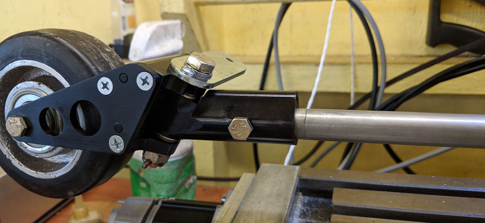
The new tailwheel, test fitted to the rod.
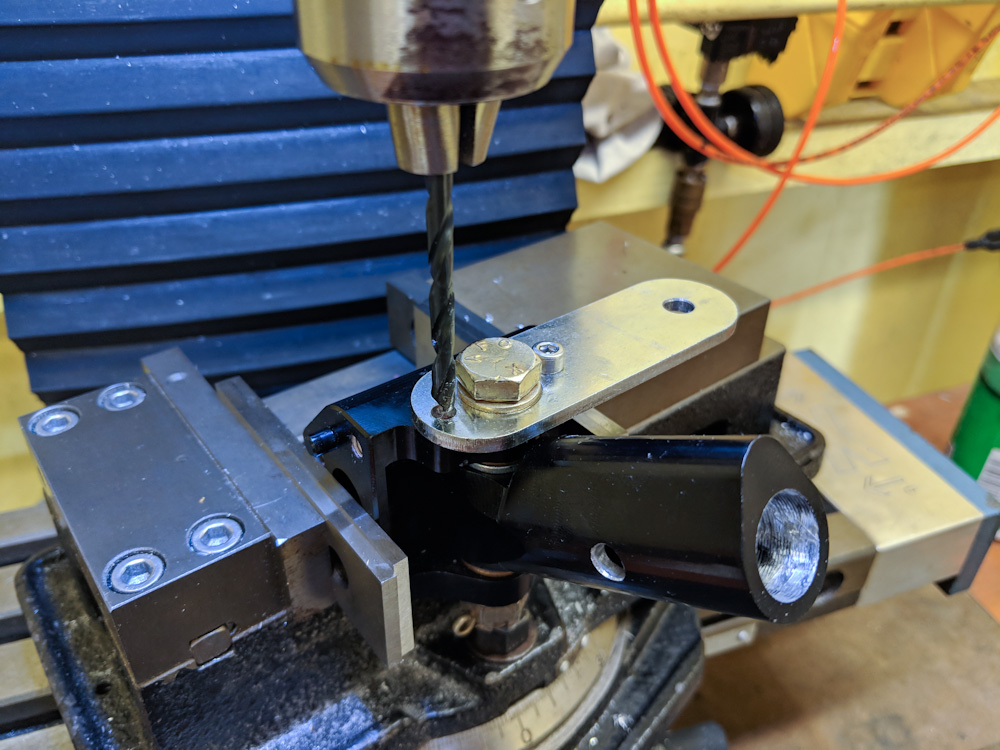
So that was not a big deal. But just as we were about to do this, Sonex came out with a Service Bulletin that said that failures of the two small screws that hold the steering link, at the top in the final picture above, had occurred and that the should be replaced with AN bolts instead. This required drilling out the threads in the aluminum tailwheel mount, so the tail wheel went back on the mill.
The tailwheel back on the mill, this time to drill out the threads for the screws that held the steering link.
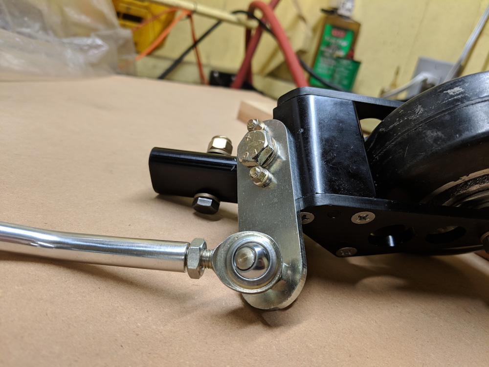
While we were at it, we also replaced the steering link. The steerable Sonex tail wheel is linked to the rudder, and the old tail wheel also had this steel link that used loose bolts as “bearings” and that had ground against the bracket that holds the rudder cable and steering link. Sonex builder Peter Anson makes a much better link that uses rod-ends and completely eliminates any binding and play in this link, so we ordered that.
The new tail wheel, complete with new hardware per the Service Bulletin and the new steering link.
Finally, the new tail wheel is back on the plane.
With that we now have new wheel bearings, new brakes, and new tail wheel. The wheels felt really smooth just rolling the plane back and forth, and the brakes worked to stop it, so I guess the next thing is to go for a short taxi to see how it works when you get everything rolling a bit.
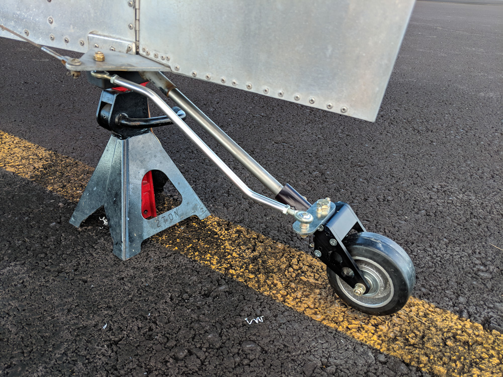
The “one thing” left to do on the Sonex was to fix the left wheel brake, which was stuck. Well, ok, the left tire also kept losing pressure. Finally co-owner Andy and I managed to get down there and jack the plane up so we could take the wheel off.
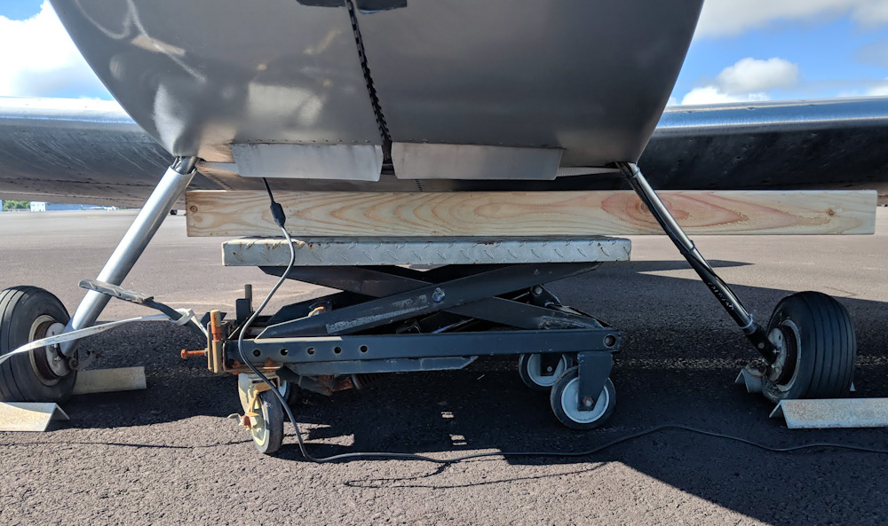
We had wondered about how to safely jack up the plane, and after reading how other people had done it ended up putting a 4×4 across the fuselage bottom immediately behind the gear. Then we jacked this up with a lift and put jackstands under the 4×4. It seems quite secure, especially with the lift in place since it gives a large support area for the 4×4, even if the jackstands themselves were to fall over somehow.
This is the lift we used to lift the plane off its gear. The jackstands are not in place yet.
Once we got the wheel off, it became apparent that this would be a somewhat larger job than anticipated, because … you guessed it: corrosion. It turns out not only was the brake arm rusted completely solid, the races of the conical wheel bearings were also rusted. That just was not acceptable, so off both wheels came off.
Everything down there was just in terrible shape. Apart from the left brake being frozen, the wheel bearing being rusty, and the tire having a slow leak, the brake drums were severely rusted all over and the aluminum wheels had pretty bad corrosion, too.
We left the plane on jackstands and I took everything home for a basic cleanup. There was so much caked brake dust everywhere that it was hard to see how bad the corrosion really was. The wheels can be split so the tire and tube can come off, and then the brake drum separated from the wheels. After some ultrasonic cleaning, it was clear that the left brake was a goner. The shaft for the actuator was completely frozen on the bushing and, instead, the bushing had spun in its mount and was now loose.
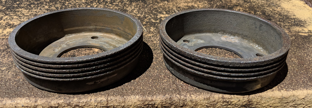
The brake drums look almost acceptable after some serious rust removal.
I dunked the brake drums in rust dissolver and left them for a week, after which they looked a lot better. The inside actually did not look that bad, and there’s barely any wear noticeable. The outsides, however, have “cooling fins” machined into the perimeter, and those were completely pitted. It took several sessions with Naval Jelly and the Dremel wire wheel before they were reasonably rust-free. Apparently they initially had a black oxide surface and that is completely useless here in Hawaii. Instead, they’re now painted with high-temperature “BBQ” black paint. This paint may interfere slightly with getting rid of brake heat, but it’s not going to be worse than a thick layer of rust.
The drums were painted with high-temperature paint. This will hopefully prevent them from rusting right away again.
The aluminum wheels also had pretty bad corrosion, especially where the brake drums had been mounted. I cleaned the mounting surface up with the wire wheel but otherwise there’s not much to do. I tried using the aluminum equivalent of Naval Jelly, but it didn’t seem to make any difference whatsoever. This corrosion is unsightly but not bad enough to affect the structure of the wheel. The wheels also aren’t visible when the wheel pants are on.
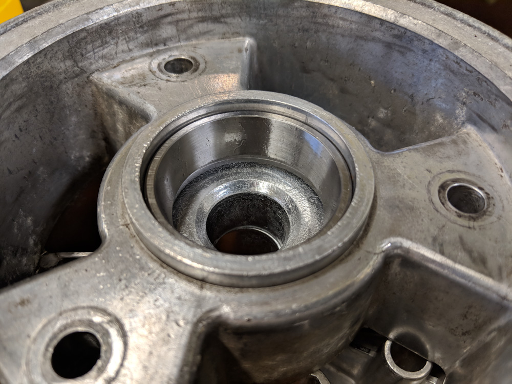
I was wondering how to get the bearing races out, since I don’t have a suitable puller. I was trying to find someone in our EAA chapter that had one, but eventually I decided I would just try to heat the wheels a bit and see if I could get them out. Indeed, it turned out that after some mild torch heating, I could pry them out. The new ones dropped right in with heat, too, so that turned out to be easier than expected.
The new bearing races slipped in cleanly after the wheels where heated a bit.
With that, the wheels were ready to be put back together. The only hitch was that one of the wheel bolts were bent enough that it did not want to go back into the hole. (I had to pound it out, initially, too.) So I have to find a 3″ 5/16 bolt somewhere. At least these wheels aren’t actually aircraft parts so they don’t use AN bolts which we definitely can’t find locally.
The wheels were massively unbalanced, so I took advantage of the wheel balancer that I got a while ago to be able to change the tires on the bikes. Spinning the wheels this way also gave me an opportunity to make sure the brake drums were reasonably centered, since they’re only held by the bolts which do not provide very precise positioning.
The only thing I’ve not been able to figure out is the leaky tire. I dunked both inner tubes in water and saw no leaks. Maybe there was some junk in one of the valves that blew out when I emptied them? I guess we’ll see.
We’re at three months since the last post… We were in Sweden for almost two months, introducing Axel to the grandparents, and after coming back I’ve not had time to write. I have however made progress on an upgrade for the mini mill that I started planning at the beginning of the year: replacing the stepper motors with servo motors.
While the stepper motors generally have worked well, I notice that I do lose steps during jobs. This becomes obvious because I frequently drill holes as the first operation, and then as the last operation run a chamfer mill over all edges. If the chamfer and the drill isn’t concentric, you can easily tell by the chamfer width changing around the perimeter of the hole.
Since steppers are open-loop systems, the motion controller tells them to do something and then you assume that it does, there is no way to detect or correct if the motor misses a step due to insufficient torque. Servo motors, DC motors with a built-in encoder, are closed loop so they will not lose position as long as they have sufficient torque to follow their commands, and if they can’t, they will tell you. This is a big advantage when it comes to the robustness of the setup.
Their construction also gives them better efficiency, especially when stationary where they will only draw as much current as necessary to hold position, while a stepper generally burns full current holding position.
The drawbacks with servos are that they are significantly more expensive than stepper motors and that the setup is more complicated. However, a line of servos called ClearPath are made for replacing stepper applications. They have integrated controllers and are controlled with step and direction inputs just like a stepper driver. This means the motion controller can control them in exactly the same way as it does steppers, which is great. This means I could continue to use the open-source G2 controller on the Arduino Due I’ve used for the steppers.
While the Arduino did not have to change, everything else did. The servos run at 75V and require a linear power supply instead of a switched one because they can better handle the large peak currents drawn by the servos when the accelerate. The Clearpath motors also use optically isolated inputs and outputs that require at least 5V to run, a lot more than what the 3.3V Due can output, so I’d need a new shield with driver transistors for all the outputs.
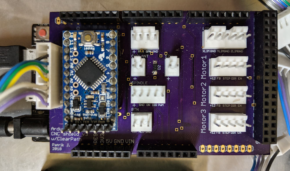
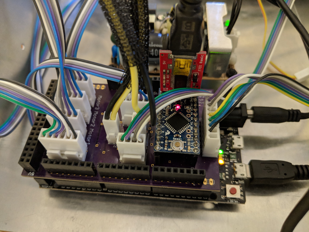
This is the new shield for the G2 Due, with connectors for the three servos, limit switches, spindle control, coolant control, and the Arduino monitoring the motors for shutdown.
There was also the question of how to handle motor shutdowns. If a stepper loses a step, it’ll keep going, so the result is likely not catastrophic. If the servo runs out of torque and can’t keep its position to within the allowable tracking error, it’ll fault and disable itself. Since having one axis on the mill suddenly stop while the others continue is unlikely to be a good experience, I wanted to a way to stop all the motors if one of them shut down. The ClearPath motors have a feedback line that indicates whether the motor is enabled or not, and can also output the current motor torque as a PWM signal.
My solution was to design a circuit that would raise a feedhold input to the G2 controller if any of the three motors shut down. That way the job would be halted, all axes (and the spindle) stopped and then you could recover. I initially attempted to design a collection of logic gates that would do this, but once I realized the motor feedback could also tell me the motor torque, which would be a useful indicator to know whether the motor is operating close to its limit, I decided that the most flexible way to do this was to take one of my Arduino Pro Minis and add it to the circuit.
The Arduino code watches the enable inputs to the motors as well as the feedback from them. The feedback consists of a 45Hz PWM signal where 50% duty cycle is 0 torque, 5% is 100% peak torque in one direction and 95% peak torque in the other. If the motor is “in position” meaning it’s stationary and just sitting there, the output is 100%, and if it’s shutdown or disabled, the output is 0%.
The strategy is that a motor whose enabled input is high but whose feedback has been low for at least 1/45 s is in shutdown and should trigger the feedhold. This is done with a simple state machine that keeps track of whether the motor is “disabled”, “enabled with feedback low”, “enabled with feedback high”, and which times out into an “alarm” state if the “enabled with feedback low” persists longer than allowed. By measuring the time in the feedback high vs low states, the PWM is measured and this is used to adjust the intensity of three LEDs that give a visual indication of how much torque the motor is outputting. If a motor goes into the alarm state, a red “shutdown” LED illuminates so it’s obvious which of the three motors caused the alarm condition.
This seems to work quite well in tests, the only problem is initializing the state at boot, if the motors are already enabled. The code can always be found in my Arduino repository if anyone’s interested.
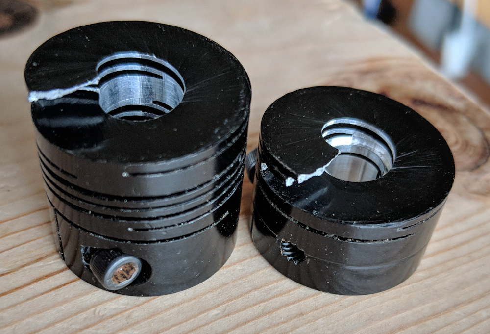
When I removed the old Z-axis stepper, I discovered that the coupler had cracked almost completely through. It only took a little axial bending for it to split into two pieces. It clearly would not have lasted much longer.
As I removed the steppers from the mill, I also discovered that the Rocom coupler that connects the Z-axis motor to the ballscrew had cracked and was close to splitting in two. This clearly is fatigue cracking and might be related to the fact that there is some wobble in the ballscrew thrust bearing, so there’s more flexing here than it should be. Crashing the machine into the workpiece and into the hardstops also probably haven’t helped…
This is the motor for the X-axis (the Y uses the same model). It is one of the smallest and cheapest Clearpath motors, the SDSK-2311S. This motor did not have enough torque for the Z-axis.
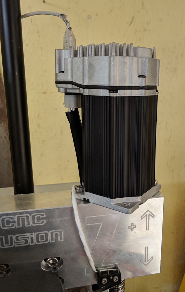
This wasn’t actually a big deal, because when I tested the motors on the Z-axis it became clear that they didn’t have enough torque to overcome the combined effect of the friction in the ways and the weight of the mill head, so I had to order a different motor that trades speed for torque. The larger motor also has a 0.375″ shaft as opposed to a 0.25″ one, so I would have had to get a new coupler in any case, even if the current one hadn’t cracked.
When I tested the XY motors on the Z-axis, it became clear that it needed a larger motor. This is the SDSK-2331S, which trades a lower max RPM for more than twice the torque (and more length.) It’s a bit more expensive, but not much. It also has a 0.375″ shaft, which required a new coupler.
I got the couplers with the CNC Fusion kit. They appear to no longer be in business, but I found you can order them directly from Rocom. However, buying a single one from them costs $100 compared to the ~$25 I paid CNC Fusion. Apparently they must have a large volume discount…
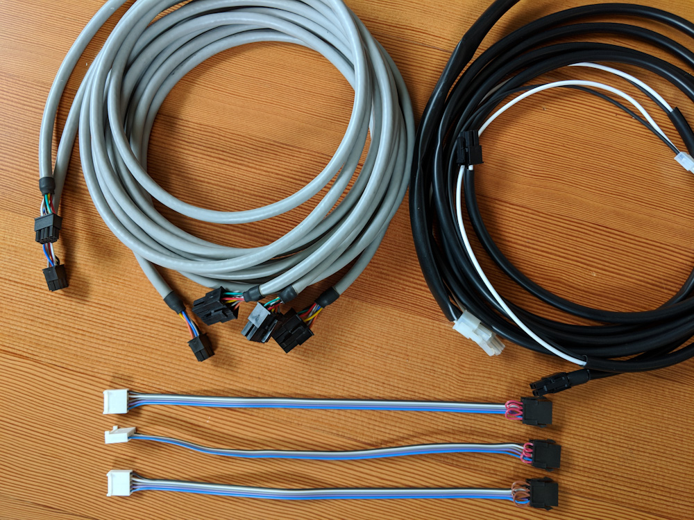
The servos do use a lot more complicated cabling than the steppers did, so there was a lot of connector crimping going on.
Once the electronics were done, I needed to make the cables. The motors use a 8-pin MiniFit connector for the signals and a 4-pin one for power. Then I needed internal cables to go from the board to the connector on the back of the box, too, so I ended up doing a lot of crimping.
The circuit board with all the connections hooked up. It’s quite busy inside there now.
Once I found a couple solder bridges on the circuit board, worked out some kinks with the Arduino code, and adjusted the motor settings in G2, it seems to run well. The servos really haul, I’m now running a max jerk setting that’s 4x what I ran with the steppers, and 50% more speed. The XY axes now traverse at 15000mm/min, while the Z-axis, with its lower speed motor, maxes out at 13000mm/min. I loaded up an old job just to see what it would look like:
The one thing I haven’t figured out yet is whether it’s possible to keep the position in case a motor shuts down. The fact that it’s shut down of course means that it’s no longer holding position, but the motors still keep track of their position commands and there’s a setting where they will return to their commanded position when they’re re-enabled. I haven’t tested this but, if it works as expected, it should be possible to move the other axes during feedhold to clear the spindle and re-enable the motor that shut down. It would then return to the position it should be and it might be possible to resume the job, which would be awesome.
Even if it’s not possible to resume the job, not losing position means that it can be canceled and restarted with suitable changes and the work coordinate system would still be valid. This is in contrast to the steppers where a lost position in practice means that you need to re-measure part zero. In principle, it would be sufficient to just re-home the axis, but the limit switches are only repeatable to something like +-0.2mm which usually is not good enough.
I’ll report back with how this works out once I’ve gotten some time on it, but for now this looks like a great upgrade.
Now that the Aerovee seems to run OK, I won’t have time to work much more on it for a while. However, as part of trying to get some full-throttle time on it, I did complete a bunch of runs with different mixtures to see what the mixture distribution looks like now.
These tests consist of running the engine at full throttle until the exhaust gas temperatures stabilize (which happens to take about as long as the cylinder head temperatures hitting redline). By doing this for different fuel flows (by changing the mixture lever between each run) and noting at which fuel flow the EGTs on the different cylinders peak, you get an indication of what mixture the cylinders are running at.
In general you do not want to run the engine at full throttle with the mixture anywhere near the peak EGT, since the heat stress and detonation margin is the smallest at this setting, but this is unfortunately the only way to get a real handle on what fuel flow we should tune for at full throttle. Since this is only for a minute at a time, and only a few minutes in total, I doubt it’ll have any adverse effects.
It takes quite a bit of time to collect these data, plot them, and read off the values. (Ideally you would do this automatically, but you need a way of selecting only the points where the temperatures and fuel flows have reached steady state. Since we’re not going to be doing this a lot, manual data collection had to suffice.)
Without further ado, here is the plot:
(Apparently WordPress doesn’t insert normal figure captions for SVG’s… Oh well.) The EGT’s are shown as a function of fuel flow at full throttle. The RPM has an arbitrary offset to just show how the max RPM varies with mixture. The dashed black lines indicate the fuel flows at which the richest and leanest cylinder EGT peaks.
While there is a fair amount of noise both in the fuel flow and EGT measurements, it appears #1 is richest, peaking at 22 liters/h. #3 and #4 are quite close and appear to peak around 23-24l/h. #2 is leanest, peaking already at 25.5 l/h. This is a spread of 3.5l/h or, as a fraction, about 15%. This should translate directly into a difference in the operating lambda of the cylinders, so if #1 is running at max power mixture which typically is something like λ=0.8, #2 would run at λ=0.95, perilously lean for full power. On the other hand, if #2 runs at λ=0.8, #1 would be more like λ=0.65, which is pig rich.
Another way of looking at it is that full rich power mixture in airplanes is typically set to be at “200 ROP”, meaning a mixture on the rich side of the peak EGT fuel flow such that the EGTs are 200F below their peak values. 200F is about 110C, so let’s try this.
#1 EGT peaks at 775C, so “200 ROP” would be at an EGT of 665C, which comes out to a fuel flow of about 29l/h. #2, on the other hand, peaks at 715C, so “200 ROP” would be 605C which is off the plot but appears to be about 35l/h.
It’s noticeable in the above plot that the #2 line, which peaks at the highest fuel flow, also seems to have a wider peak than the others. I tried plotting each of the EGTs as a function of the fuel flow normalized to the fuel flow that gives the peak EGT for that cylinder. Since peak EGT basically is stoichiometric mixture, or λ=1, this should be a proportional to the lambda of that cylinder (more precisely proportional to 1/λ.) If you do that, and normalize all the EGTs to their respective peak values, you get this:So the shapes are actually quite similar, with the notable exception that the #2 cylinder stays hot on the lean side for longer than the others. I believe this has to do with the RPM, when the leanest cylinder starts going lean, the RPM does not drop much, if at all, because its lower power is offset by the fact that the other, richer, cylinders are increasing their power. Once the richest cylinder has peaked and all cylinders are operating lean, further leaning will decrease power output quite rapidly and the RPM will drop. Since higher RPM in general means higher EGT’s, this would tend to keep the EGT for #2 on the lean side higher than for #4 which drops very steeply. On the rich side of the peak, the curves have a remarkably similar slope.
In this view, “200 ROP” would correspond to a fuel flow of about 1.32 times that of peak, or λ=1/1.32=0.76. That’s very rich, but full rich is supposed to be very rich to provide detonation margins on climbout. Best power mixture in aircraft is generally assumed to be “140 ROP”, or about -80C on the plot above. This corresponds to a fuel flow of 1.26 or λ=1/1.26=0.79. That’s a bit richer than the 12.5:1 or λ=0.85 that’s often stated when tuning cars, but pretty close.
So where does that leave us? Running the leanest cylinder 200ROP, at 35l/h, is so very rich for the other cylinders that I think we have to compromise on that. 32.5l/h will run the leanest cylinder at at about best power, so we should stay on the rich side of that.
It’s also worth testing if closing the throttle just a little bit, which tends to increase turbulence in the intake, can help even out the mixture. I did some testing at partial throttle and in that situation the mixture seems a lot more uniform. A more turbulent flow in the intake, as well as the lower pressure in the plenum, will help atomize the fuel, so that’s expected. But I’ll leave investigations of that until the plane is actually flying again.
In the time since the engine was replaced on the plane, I’ve been able to get down to the airport every now and then and work on hooking everything up.
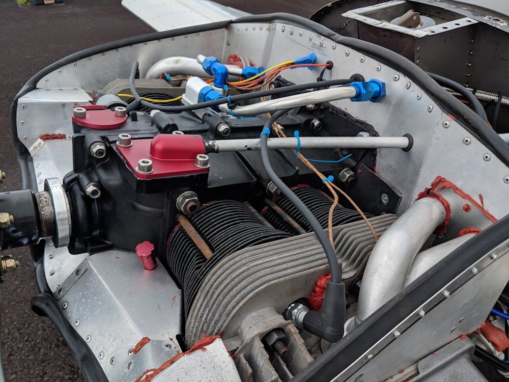
The biggest thing to put together was the oil system. The lines to the oil filter and oil cooler had to be fabricated and I ran into some leaks and had to take things apart and redo it. There was also an unexpected ignition timing issue.
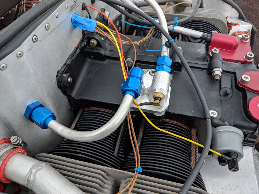
The CNC-machined adapter mounting on the oil cooler plate has two hard lines going to the passthroughs that take the oil lines through the baffles. This is also where the oil temperature sensor is mounted now, which ensures an accurate reading of what the temperature of the oil coming out of the pump is.
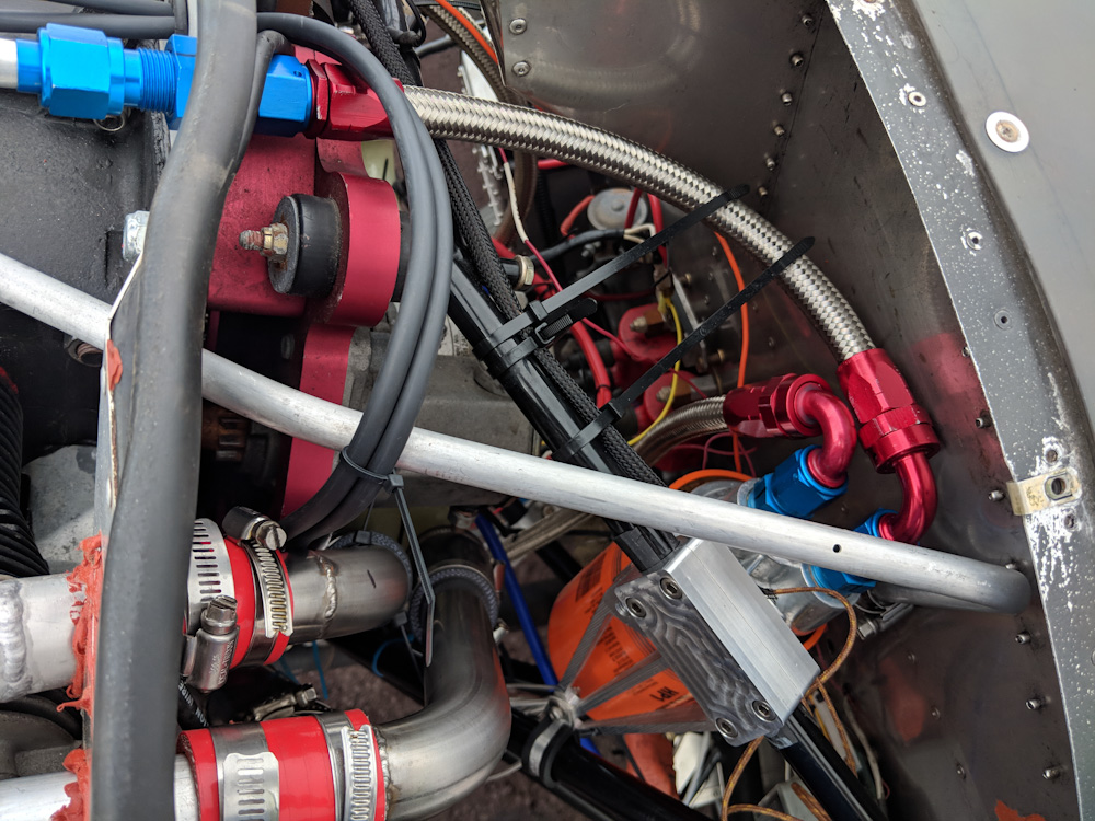
From the passthrough, there is a short hose running to the oil filter which is mounted on the engine mount tubing. The outlet from the oil filter has another hose going down to the oil cooler. This picture also shows the new routing of the ignition wires from the bottom magnetron to the front cylinders, as explained below.
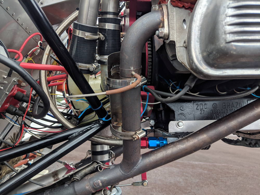
This picture shows the lower hose going from the oil filter to the oil cooler (which has been turned around 180 degrees compared to how it is originally mounted.) This put the oil cooler outlet very close to the exhaust, and I had to remove some material from the outer fins on the cooler to avoid interference. The ignition wire splices are faintly visible just above the bend in the rear exhaust header.
From the oil cooler, a longer hose goes back up to the pass-through going through the right side of the baffles and then back to the oil cooler adapter.
After fitting all the oil lines, the engine was cranked with spark plugs removed and the pushrods not yet fitted. This makes the engine turn over really easily since there is no compression and no valve springs to push against. After running the starter for maybe 20 seconds we got good oil pressure, so then the spark plugs were replaced, the pushrods installed, and the valve clearance checked. Time to start it.
On the first start attempt, the engine was cranked for a while without any trace of ignition and then we were greeted with an epic backfire. The pop was strong enough to crack the screw ears on the 3D printed plenum. Not good. Luckily, while the joint between the plenum halves had separated a bit, the plenum itself appears undamaged.
Now, a backfire typically indicates that the ignition timing is like 180 degrees off, so the spark plug fires while the intake valve is open and fuel/air mixture is being drawn into the cylinder. However, the ignition timing of the primary ignition is fixed, and the secondary should have been put back where it was, so I was unsure how this worked.
I did attempt to check the ignition timing with a timing light before starting, but the light is not bright enough to be seen when you’re out on the apron in bright sunlight, so I didn’t manage to do that. I returned at dusk and hooked the timing light up again and confirmed that the ignition timing indeed was pretty much exactly 180 degrees off. How is this possible, when the ignition is fixed on the flywheel, which can only be mounted in one orientation on the crankshaft?
The only solution is that the Force One crankshaft that we got from Great Plains mounts the flywheel in a different orientation than the Sonex crankshaft. Indeed, I’ve subsequently heard from other people who ran into the same issue, so that is indeed the case. (Great Plains uses a distributor timing, so they probably don’t care about the exact clocking of the flywheel.)
To verify this, I reoriented the adjustable secondary ignition and tried starting again. Lo and behold, it started and ran like a clock. So the issue then was what to do about the non-adjustable primary ignition. The simplest would be to exchange the ignition wires going to the front and rear spark plug pairs, respectively, since those are 180 degrees out of phase. The problem is that the ignition wire is not long enough to go from the bottom magnetron up to the top of the engine, through the baffles, and then out to the front cylinders.
I considered trying to replace the ignition wires by pulling them out of the magnetrons, but someone said they had successfully used a spark plug wire splice made by NGK to do the same thing. I ordered a pair of those, and a couple meters of the identical type of ignition wire, off ebay and it worked beautifully. Time will tell whether the splices will hold up to heat and vibration, but for now the ignition timing issue has been successfully mitigated.
Once I started running the engine seriously and getting the oil temp up a bit, I noticed numerous oil leaks. The blue anodized fittings on the oil lines use NPT threads, and they leaked both in the adapter on top of the engine and at the oil filter. I had sealed those with Hylomar, and that apparently did not work. I removed them and attempted to use Permatex Aviation, but that also leaked. Finally I took the parts home so they could be cleaned really well, and used Loctite thread sealant paste and primer on the threads. That did the trick, no more leaks.
With those leaks fixed, I ran the engine a bit longer and got the oil up to about 190F, and then I noticed two more leaks. These were from two of the large oil plugs that replaced the freeze plugs that were extracted to be able to clean out the oil galleries. This was a bit disappointing since those were staked to not come out. That being said, I had also used Permatex Aviation on those, so I guess it was time to try the thread sealant paste here too.
Luckily the plugs came out pretty easily, and I cleaned the threads as best I could (without spraying too much mineral spirits into the oil gallery), applied primer and thread sealant paste and tightened them back up real snugly. They weeped a bit the next time I ran the engine again, but tightening them a bit more while the engine was warm appears to have put enough pressure on the threads to seal it up. Yay, no more leaks.
Once the engine ran fine, there was another concern: the oil pressure was very high, around 95 psi at cold idle. This is a symptom of the oil pressure plungers being stuck, but I had verified they were not quite carefully on assembly and when I opened the plunger bores they did come out without too much trouble. What I did discover is that we have a 0-5 bar oil pressure sender, but the Enigma was calibrated for 0-10 bar. What this means is that the oil pressure really was half of what was indicated. And had been for the lifetime of the plane?!?
After correcting the calibration, we have 45 psi which is exactly the pressure that the pressure relief valve should open at, so that agrees well. However, it means the oil pressure before the rebuild was completely inadequate. I looked at an old data log from the plane flying before I bought it and, with the oil temp at 210F, the oil pressure read 12 psi or so at 3000 RPM. That’s already low, but now we know that was actually 6 psi which is about when the stock VW oil pressure light would be coming on. (This was also with 20W-50 oil, and now we are running 10W-30.) Given how worn the bearings were, I guess it’s not surprising the oil pressure would not hold up, but the flip side is that it’s not strange the engine was all worn out.
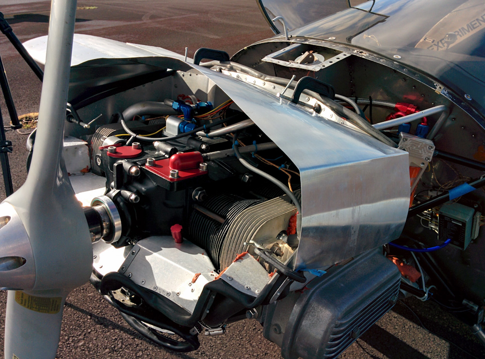
With all that worked out, I cleaned up the installation, ziptied the wiring, and remounted all the baffles.
An overview of the top of the engine after all the wires have been routed and attached reasonably.
With no leaks and everything looking good, it was time to worry about breaking in the engine. Since you can’t run the engine on the ground for even a minute before the CHTs hit redline, it’s hard to get any kind of time at high power levels, which is what you want to break the cylinders in.
I noted that in some pictures from the Sonex factory, they use a big air scoop mounted on top of the engine to get enough air through the cylinders when running in the test cell. I decided to try that approach, so I took some aluminum sheet and made a makeshift air scoop.
This is the make shift air scoop I added to get more air through the cylinders on the ground. Here the sheet is held in place with screw clamps, but that vibrates loose after a while so I replaced the front clamps with M4 screws through the baffle. I also riveted a aluminum extrusion along the front of the scoop to avoid it bowing under the air pressure.
There’s a lot of airflow at full throttle, so holding the scoop in place took a little fiddling, and eventually I drilled a 4mm hole through the baffles in the front so I could bolt it in place.
The scoop does make a difference, the head temperatures rise about half as fast at full throttle as without it, but it’s not enough to be able to run more than about 2400RPM on the ground without eventually running into the temperature redline. But it did make it possible for me to run for about half an hour with about a minute spurts of full power and then 5 minutes of cooling down to get some full throttle time on it. It runs well and sounds good so I’m going to call this good enough to actually go flying. Here’s a test run:
The only problem is that there’s a bunch of other things on the plane that needs fixing. I’ve told the co-owners I’m not doing any of that, so now it’s time for them to step up to the plate.
This isn’t really a project post, but some of you may be aware that Kilauea volcano here on the Big Island is having a bit of an eruption right now. Two weeks ago there was a magnitude 6.9 earthquake, the largest to hit the island since 1975. This was stronger than anything we ever felt in California. Then lava started pouring out of the ground in Kilauea’s lower east rift zone, in Puna. The eruption has slowly picked up pace and at this point there are spectacular lava fountains and literal rivers of lava going into the ocean. You can find countless videos on Youtube.
What I did not expect was that they would be visible from our house in Hilo! Tonight was a pretty clear night and off to the southeast is a bright, orange glow. While you can’t see the lava itself, the illuminated smoke from the three largest eruption sites is clearly visible. This is approximately 25 miles (40 km) away.
This is the Kilauea lava flow seen from our window in Hilo, captured using a 200mm lens.
There is no danger to Hilo from this flow, the topography is such that the lava will run southeast or at worst north from the eruption site. However, it’s pretty bad for the people in Puna. Even if only about 40 houses so far have been lost to the lava, there’s enough SO2 outgassing to make it pretty unhealthy to be anywhere in a pretty large radius, depending on how the wind blows, and several thousand people have been evacuated. The lava has also cut off two of the three roads by which you can get down to the ocean in that area, so there’s also a significant number of people that may be cut off.