In the time since the engine was replaced on the plane, I’ve been able to get down to the airport every now and then and work on hooking everything up.
The biggest thing to put together was the oil system. The lines to the oil filter and oil cooler had to be fabricated and I ran into some leaks and had to take things apart and redo it. There was also an unexpected ignition timing issue.
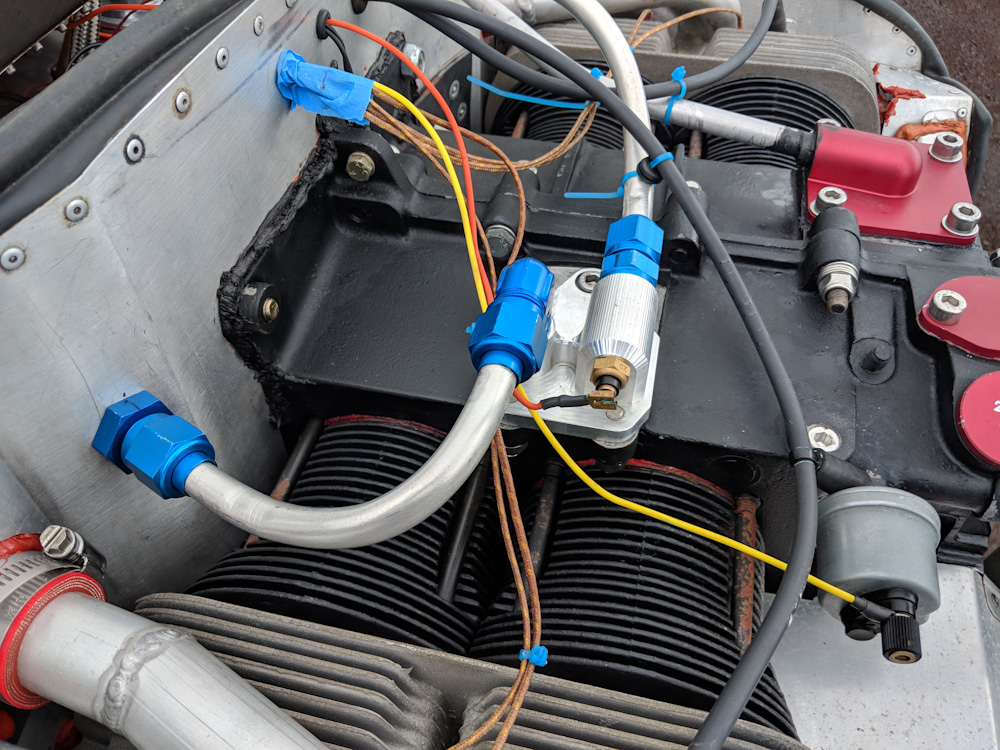
The CNC-machined adapter mounting on the oil cooler plate has two hard lines going to the passthroughs that take the oil lines through the baffles. This is also where the oil temperature sensor is mounted now, which ensures an accurate reading of what the temperature of the oil coming out of the pump is.
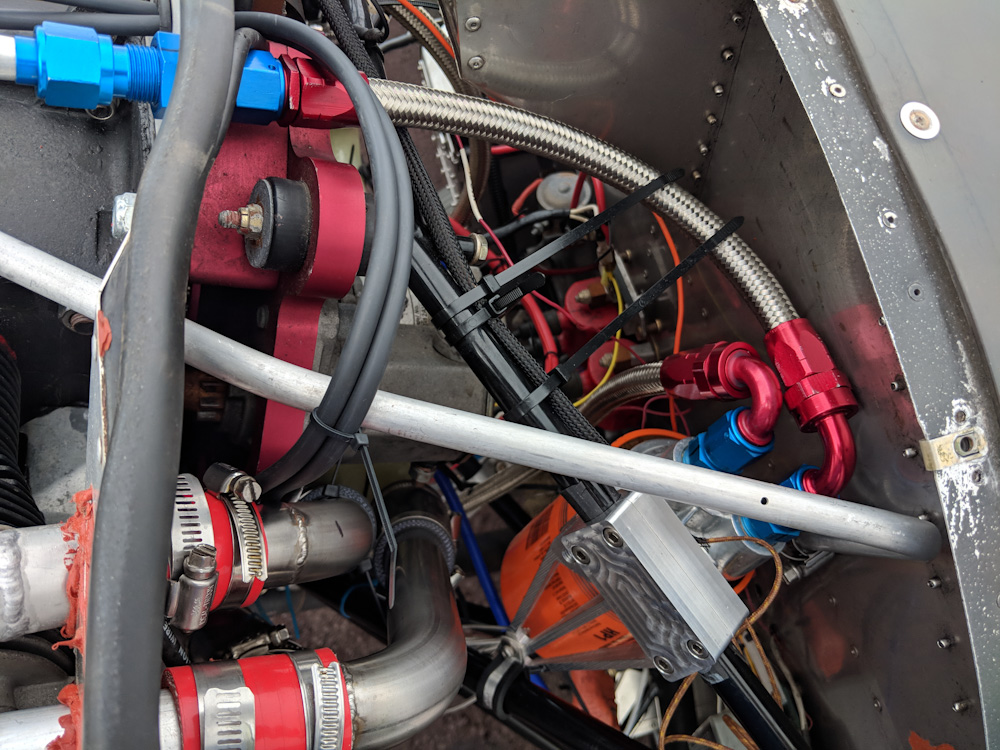
From the passthrough, there is a short hose running to the oil filter which is mounted on the engine mount tubing. The outlet from the oil filter has another hose going down to the oil cooler. This picture also shows the new routing of the ignition wires from the bottom magnetron to the front cylinders, as explained below.

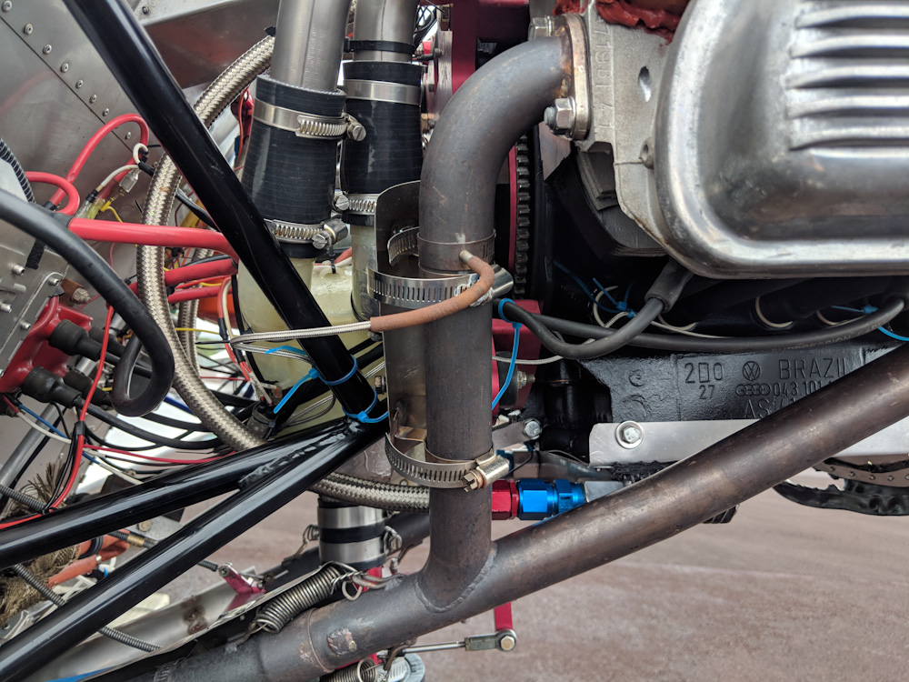
This picture shows the lower hose going from the oil filter to the oil cooler (which has been turned around 180 degrees compared to how it is originally mounted.) This put the oil cooler outlet very close to the exhaust, and I had to remove some material from the outer fins on the cooler to avoid interference. The ignition wire splices are faintly visible just above the bend in the rear exhaust header.
From the oil cooler, a longer hose goes back up to the pass-through going through the right side of the baffles and then back to the oil cooler adapter.
After fitting all the oil lines, the engine was cranked with spark plugs removed and the pushrods not yet fitted. This makes the engine turn over really easily since there is no compression and no valve springs to push against. After running the starter for maybe 20 seconds we got good oil pressure, so then the spark plugs were replaced, the pushrods installed, and the valve clearance checked. Time to start it.
On the first start attempt, the engine was cranked for a while without any trace of ignition and then we were greeted with an epic backfire. The pop was strong enough to crack the screw ears on the 3D printed plenum. Not good. Luckily, while the joint between the plenum halves had separated a bit, the plenum itself appears undamaged.
Now, a backfire typically indicates that the ignition timing is like 180 degrees off, so the spark plug fires while the intake valve is open and fuel/air mixture is being drawn into the cylinder. However, the ignition timing of the primary ignition is fixed, and the secondary should have been put back where it was, so I was unsure how this worked.
I did attempt to check the ignition timing with a timing light before starting, but the light is not bright enough to be seen when you’re out on the apron in bright sunlight, so I didn’t manage to do that. I returned at dusk and hooked the timing light up again and confirmed that the ignition timing indeed was pretty much exactly 180 degrees off. How is this possible, when the ignition is fixed on the flywheel, which can only be mounted in one orientation on the crankshaft?
The only solution is that the Force One crankshaft that we got from Great Plains mounts the flywheel in a different orientation than the Sonex crankshaft. Indeed, I’ve subsequently heard from other people who ran into the same issue, so that is indeed the case. (Great Plains uses a distributor timing, so they probably don’t care about the exact clocking of the flywheel.)
To verify this, I reoriented the adjustable secondary ignition and tried starting again. Lo and behold, it started and ran like a clock. So the issue then was what to do about the non-adjustable primary ignition. The simplest would be to exchange the ignition wires going to the front and rear spark plug pairs, respectively, since those are 180 degrees out of phase. The problem is that the ignition wire is not long enough to go from the bottom magnetron up to the top of the engine, through the baffles, and then out to the front cylinders.
I considered trying to replace the ignition wires by pulling them out of the magnetrons, but someone said they had successfully used a spark plug wire splice made by NGK to do the same thing. I ordered a pair of those, and a couple meters of the identical type of ignition wire, off ebay and it worked beautifully. Time will tell whether the splices will hold up to heat and vibration, but for now the ignition timing issue has been successfully mitigated.
Once I started running the engine seriously and getting the oil temp up a bit, I noticed numerous oil leaks. The blue anodized fittings on the oil lines use NPT threads, and they leaked both in the adapter on top of the engine and at the oil filter. I had sealed those with Hylomar, and that apparently did not work. I removed them and attempted to use Permatex Aviation, but that also leaked. Finally I took the parts home so they could be cleaned really well, and used Loctite thread sealant paste and primer on the threads. That did the trick, no more leaks.
With those leaks fixed, I ran the engine a bit longer and got the oil up to about 190F, and then I noticed two more leaks. These were from two of the large oil plugs that replaced the freeze plugs that were extracted to be able to clean out the oil galleries. This was a bit disappointing since those were staked to not come out. That being said, I had also used Permatex Aviation on those, so I guess it was time to try the thread sealant paste here too.
Luckily the plugs came out pretty easily, and I cleaned the threads as best I could (without spraying too much mineral spirits into the oil gallery), applied primer and thread sealant paste and tightened them back up real snugly. They weeped a bit the next time I ran the engine again, but tightening them a bit more while the engine was warm appears to have put enough pressure on the threads to seal it up. Yay, no more leaks.
Once the engine ran fine, there was another concern: the oil pressure was very high, around 95 psi at cold idle. This is a symptom of the oil pressure plungers being stuck, but I had verified they were not quite carefully on assembly and when I opened the plunger bores they did come out without too much trouble. What I did discover is that we have a 0-5 bar oil pressure sender, but the Enigma was calibrated for 0-10 bar. What this means is that the oil pressure really was half of what was indicated. And had been for the lifetime of the plane?!?
After correcting the calibration, we have 45 psi which is exactly the pressure that the pressure relief valve should open at, so that agrees well. However, it means the oil pressure before the rebuild was completely inadequate. I looked at an old data log from the plane flying before I bought it and, with the oil temp at 210F, the oil pressure read 12 psi or so at 3000 RPM. That’s already low, but now we know that was actually 6 psi which is about when the stock VW oil pressure light would be coming on. (This was also with 20W-50 oil, and now we are running 10W-30.) Given how worn the bearings were, I guess it’s not surprising the oil pressure would not hold up, but the flip side is that it’s not strange the engine was all worn out.
With all that worked out, I cleaned up the installation, ziptied the wiring, and remounted all the baffles.
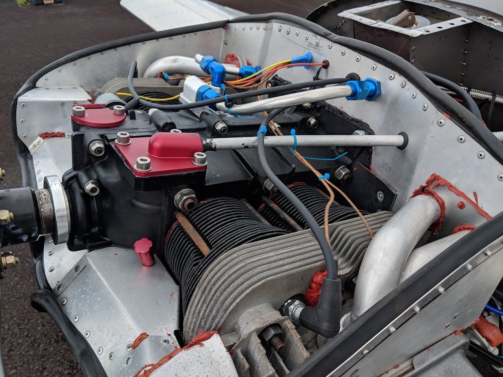
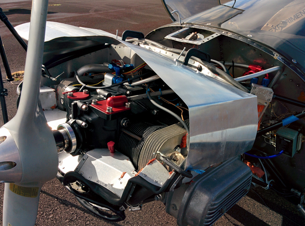
An overview of the top of the engine after all the wires have been routed and attached reasonably.
With no leaks and everything looking good, it was time to worry about breaking in the engine. Since you can’t run the engine on the ground for even a minute before the CHTs hit redline, it’s hard to get any kind of time at high power levels, which is what you want to break the cylinders in.
I noted that in some pictures from the Sonex factory, they use a big air scoop mounted on top of the engine to get enough air through the cylinders when running in the test cell. I decided to try that approach, so I took some aluminum sheet and made a makeshift air scoop.
This is the make shift air scoop I added to get more air through the cylinders on the ground. Here the sheet is held in place with screw clamps, but that vibrates loose after a while so I replaced the front clamps with M4 screws through the baffle. I also riveted a aluminum extrusion along the front of the scoop to avoid it bowing under the air pressure.
There’s a lot of airflow at full throttle, so holding the scoop in place took a little fiddling, and eventually I drilled a 4mm hole through the baffles in the front so I could bolt it in place.
The scoop does make a difference, the head temperatures rise about half as fast at full throttle as without it, but it’s not enough to be able to run more than about 2400RPM on the ground without eventually running into the temperature redline. But it did make it possible for me to run for about half an hour with about a minute spurts of full power and then 5 minutes of cooling down to get some full throttle time on it. It runs well and sounds good so I’m going to call this good enough to actually go flying. Here’s a test run:
The only problem is that there’s a bunch of other things on the plane that needs fixing. I’ve told the co-owners I’m not doing any of that, so now it’s time for them to step up to the plate.
Looks very professional with the blue zip-ties. But is that some blue masking tape in there as well?
Sharp eye there, yes, aerospace-grade tefzel masking tape.
Temporary to protect the wires when I was fitting the aluminum scoop. 😉
Pingback: Engine measurements – Patrik's projects