The last post explained what the motion controller needs to do. This post will deal with the actual assembly of the electronics.
The G251X motor controllers can run up to 50V, and higher voltage makes higher speeds possible (you need the higher voltage to counter the back emf from the motors, which gets higher the faster they move) so most people recommend getting a 48V power supply. The motor controllers also need heat sinking, so I got a large aluminum case that should provide a sufficient heat sink if the motor controllers are mounted to them.
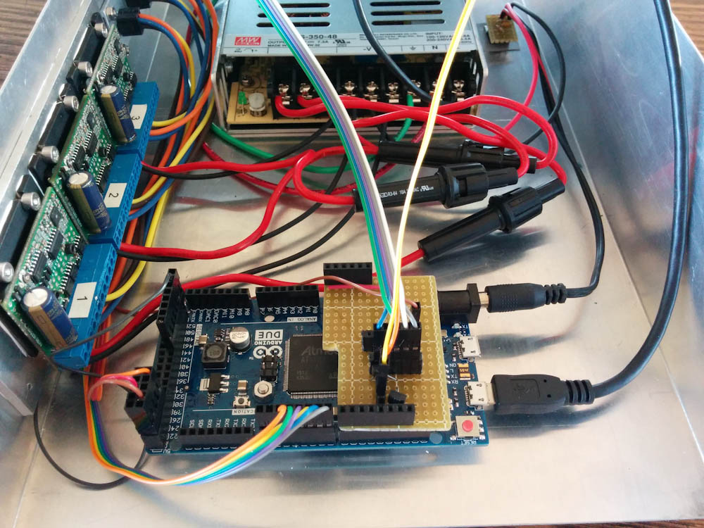
The guts of the electronics box. Front and center is the Arduino Due running TinyG, mounted to the case on the left are the motor controllers, in the back in the 48V power supply. In the upper right is the linear regulator supplying 12V to the Arduino.
The G251X motor controllers can supply up to 3.5A to the motors, but the ones I got run on 2.7A so they aren’t even really being pushed. They still get plenty warm though. Interestingly, when I got them there was no thermal paste between the driver MOSFETs and the aluminum heat sink. In fact, some of them weren’t even making contact. I asked Geckodrive support if that was intentional and they basically said “it’ll be fine”. I thought that was strange because the instructions say that you must use thermal paste between the heatsink and the case when mounting them… I added some paste.
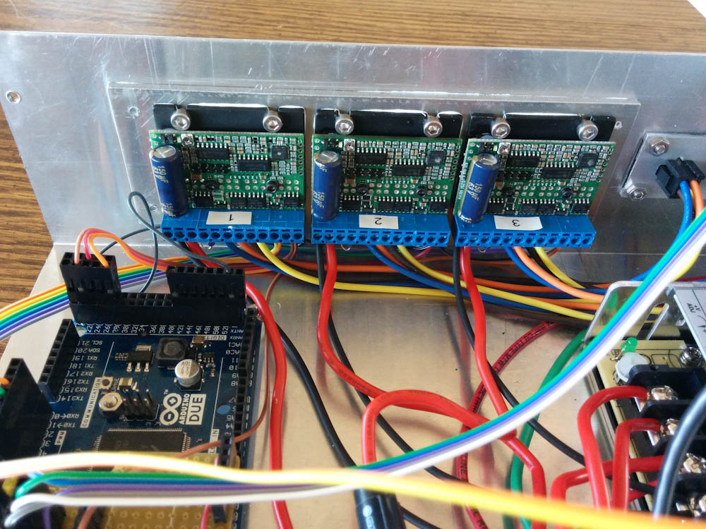
These are the three G251X motor controllers. They are mounted to a thick aluminum plate and then to the case for heatsinking.
One drawback with the G251X controllers is that they have no protection circuits. If you short the motor outputs to each other or to ground, you’ll burn the MOSFETs. The instructions state this, so it was with great dismay I popped one of them when I attempted to measure the motor voltage on the oscilloscope and didn’t make the “connection” that the ground lead on the scope really is connected to ground… Luckily it was a simple matter de-soldering the bad RFD3055LE (it was shorted, so it was obvious which one it was) and replacing it with a new one from Mouser. That lesson could have turned out much more expensive than 60 cents!
I used MicroFit 3.0 connectors for the motors and spindle control. I have a whole set of them and they are good to 5A so that works well. The only problem is that you have to cut out a rather intricate shape in the panel to mount them. Luckily I have a new mill! I did this by hand-milling, before the CNC kit had arrived. Working with the 1/16″-per-turn hand wheels did require some mental exercise, but by the 4th connector I was pretty good at it… I’m not sad to see them go, though. The whole case is too large to fit in the mill, so I used a 1/8″ aluminum plate and milled the panel cutouts in it, and then just cut a large, square hole in the case and screwed it in place. It worked out OK, but the connector holes aren’t quite lined up because I took out the plate for inspection between holes.
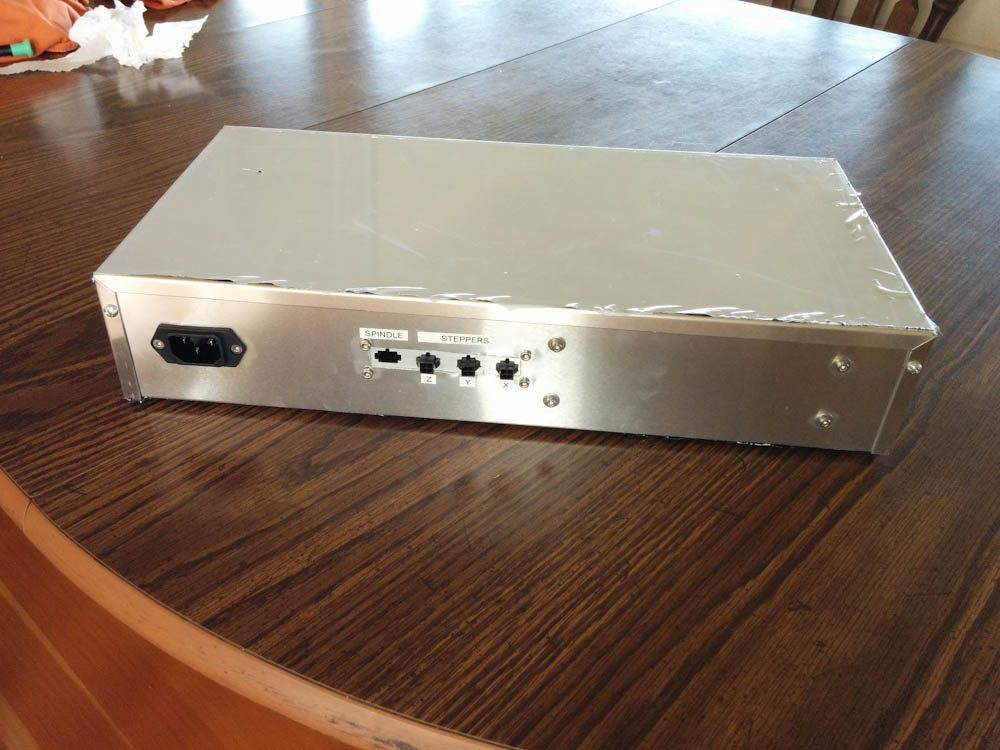
The back side with the connectors for the motors and spindle controller. The spindle controller connector isn’t mounted yet.
On the front side, I added some LEDs to show whether the motors and spindle are powered, as well as a lockout switch that prevents TinyG from starting the spindle so you can change tools etc without risk of getting your hand milled off. There’s also the USB connector so you can connect to the Arduino, and an emergency stop.
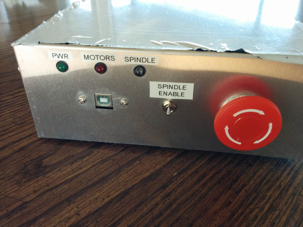
The front has three LEDs indicating whether the box has power, the motors are enabled, and the spindle is enabled. There is a spindle lockout switch that can be used to make sure the spindle doesn’t start when you are changing tools. And then the emergency stop, which kills power to the whole box. And yes, I am cronically unable to put labels on straight…
So far everything was pretty straightforward. All I had to do was wire the motor outputs from the Arduino to the motor controllers, and I successfully could run the motors. The only small snag was that the “motor enable” input on the G251X is high for enabling the motors, but TinyG (which otherwise is quite configurable) has a fixed polarity of enabled-low for the enable outputs. I’m not the only one who ran into this problem, and I found suggestions for how to make this polarity configurable on the TinyG issue tracker. First win for open source solutions!
Of course, the Arduino needs power to run (it can take power from the USB cable, but you really don’t want it to die if the cable is unplugged) so I added a LM317 voltage regulator to convert the 48V from the power supply to the 12V that is the max input voltage to the Arduino. It really runs on 5V and 3.3V, but I wanted 12V to power the spindle and coolant outputs. Using a linear regulator like the LM317 to step down from 48V to 12V is hugely inefficient, but the Arduino doesn’t use much current so I bolted it to the case and it didn’t even get particularly warm.
However, I mentioned coolant. With the mill I got a little mist coolant sprayer that runs on pressurized air. For the Arduino to switch the coolant on and off, I ordered an air valve solenoid that runs on 12V. It’s a pretty small one, so it only uses 0.5A, but that’s a whole lot more than what the Arduino pulls. It’s switched with a MOSFET controlled by the coolant enable pin on the Arduino, but this is where things started going south. It worked fine, but pulling 0.5A through the LM317 would mean a power dissipation of (48V-12V)*0.5A = 18W. That’s a lot. When I issued the command to turn the coolant on to TinyG, the bottom of the case where the voltage regulator was mounted quickly became so hot I couldn’t touch it. This was not going to work.
The solution to inefficient linear regulators is of course: use a switching step-down converter instead. The problem is that actually requires a real circuit, and high switching frequencies means you can’t really hack it up on the Veroboard. You need a dedicated circuit board.
Then I remembered that I actually have an abandoned board with a MC33063 step-down controller that was a first edition for the fan control Arduino in my computer. I don’t remember why I abandoned it, but maybe I could re-purpose that circuit? After some measuring, troubleshooting, and substitution of components, I actually got it to work. The problem is that the max input voltage to the MC33063 is only 40V, so I’d still need the linear regulator. Oh well, stepping down from 48V to 39V is still a whole lot better than from 48V to 12V… Should work.
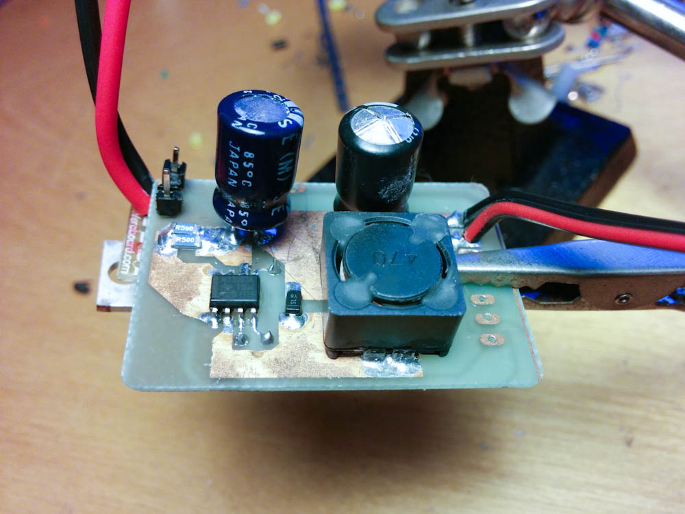
The ill-fated, repurposed buck controller board mounted on top of the LM317 sticking out to the left. Note the bulging top on the output capacitor on the right…
The picture above shows the buck converter board strapped to the top of the LM317. I tried the board on the bench power supply first, but it only goes to 30V, so I didn’t have a way of testing it at the full input voltage without actually hooking it up to the 48V supply. I did, and it seemed to work. The output was 11.7V, so I plugged it in to the Arduino and fired it up. No problems. Time to try switching the solenoid.
With the solenoid plugged in, I typed the command to turn it on. It seemed fine, so I typed the command to turn it off. A second later I was rewarded with a loud pop and a puff of smoke from the Arduino! What the?
I unplugged the regulator from the now-smelly Arduino and turned the power back on. Output voltage, 24V! That’s not right! A second later, another loud pop and the 16V output capacitor on the regulator board burst.
Sadness. I’m not sure what happened, but it appears the switch transistor in the MC33063 is now shorted. If that happens on a buck converter (see for example this schematic on Wikipedia), there is a direct connection from the input, through the inductor, to the output. Maybe I picked the 39V input too close to the 40V maximum. When the switch opens, the voltage across it will rise until the diode conducts, so perhaps that was enough to cause the switch to break down?
In any case, the Arduino is dead. Luckily the laptop USB port is OK, so it didn’t shoot the voltage out that way. I’m not sure about the motor controllers, since I have no way of testing them without the Arduino. I sure hope they’re OK, otherwise this lesson will turn out to be a lot more expensive than the 60-cent one earlier…
So it’s back to the drawing board here. A new Arduino is on order, and I’m going to design a real circuit board with the stepdown regulator, with over-voltage protection on the output this time, and add all the little circuits I needed for the coolant switch, spindle control (which I haven’t talked about yet, that’ll be another post). I’ll just make this board fit over the whole Due so I don’t have to deal with jumper cables to collect all the output pins. Less loose connections means less things to wire wrong. It’ll be better, but getting that board manufactured will set the project back quite a bit… Oh well, in the mean time I can work on mounting the limit switches.
Pingback: CNC Mini Mill #4: Small tweaks | Patrik's projects
Pingback: CNC Mini Mill #6: The Arduino shield | Patrik's projects
Pingback: CNC mill upgrade: servos – Patrik's projects