We’re at three months since the last post… We were in Sweden for almost two months, introducing Axel to the grandparents, and after coming back I’ve not had time to write. I have however made progress on an upgrade for the mini mill that I started planning at the beginning of the year: replacing the stepper motors with servo motors.
While the stepper motors generally have worked well, I notice that I do lose steps during jobs. This becomes obvious because I frequently drill holes as the first operation, and then as the last operation run a chamfer mill over all edges. If the chamfer and the drill isn’t concentric, you can easily tell by the chamfer width changing around the perimeter of the hole.
Since steppers are open-loop systems, the motion controller tells them to do something and then you assume that it does, there is no way to detect or correct if the motor misses a step due to insufficient torque. Servo motors, DC motors with a built-in encoder, are closed loop so they will not lose position as long as they have sufficient torque to follow their commands, and if they can’t, they will tell you. This is a big advantage when it comes to the robustness of the setup.
Their construction also gives them better efficiency, especially when stationary where they will only draw as much current as necessary to hold position, while a stepper generally burns full current holding position.
The drawbacks with servos are that they are significantly more expensive than stepper motors and that the setup is more complicated. However, a line of servos called ClearPath are made for replacing stepper applications. They have integrated controllers and are controlled with step and direction inputs just like a stepper driver. This means the motion controller can control them in exactly the same way as it does steppers, which is great. This means I could continue to use the open-source G2 controller on the Arduino Due I’ve used for the steppers.
If you’ve not seen my existing setup, I encourage you to go back and read The mini mill motion controller, The mini mill electronics box, and CNC Mini Mill #6: The Arduino shield for more information about the existing setup. It’ll make this post easier to follow.
While the Arduino did not have to change, everything else did. The servos run at 75V and require a linear power supply instead of a switched one because they can better handle the large peak currents drawn by the servos when the accelerate. The Clearpath motors also use optically isolated inputs and outputs that require at least 5V to run, a lot more than what the 3.3V Due can output, so I’d need a new shield with driver transistors for all the outputs.
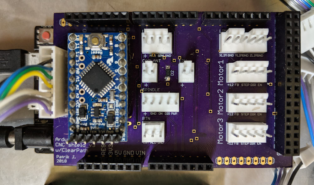
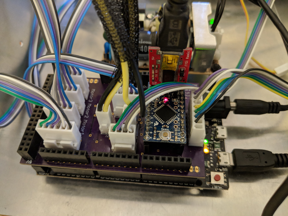
This is the new shield for the G2 Due, with connectors for the three servos, limit switches, spindle control, coolant control, and the Arduino monitoring the motors for shutdown.
There was also the question of how to handle motor shutdowns. If a stepper loses a step, it’ll keep going, so the result is likely not catastrophic. If the servo runs out of torque and can’t keep its position to within the allowable tracking error, it’ll fault and disable itself. Since having one axis on the mill suddenly stop while the others continue is unlikely to be a good experience, I wanted to a way to stop all the motors if one of them shut down. The ClearPath motors have a feedback line that indicates whether the motor is enabled or not, and can also output the current motor torque as a PWM signal.
My solution was to design a circuit that would raise a feedhold input to the G2 controller if any of the three motors shut down. That way the job would be halted, all axes (and the spindle) stopped and then you could recover. I initially attempted to design a collection of logic gates that would do this, but once I realized the motor feedback could also tell me the motor torque, which would be a useful indicator to know whether the motor is operating close to its limit, I decided that the most flexible way to do this was to take one of my Arduino Pro Minis and add it to the circuit.
The Arduino code watches the enable inputs to the motors as well as the feedback from them. The feedback consists of a 45Hz PWM signal where 50% duty cycle is 0 torque, 5% is 100% peak torque in one direction and 95% peak torque in the other. If the motor is “in position” meaning it’s stationary and just sitting there, the output is 100%, and if it’s shutdown or disabled, the output is 0%.
The strategy is that a motor whose enabled input is high but whose feedback has been low for at least 1/45 s is in shutdown and should trigger the feedhold. This is done with a simple state machine that keeps track of whether the motor is “disabled”, “enabled with feedback low”, “enabled with feedback high”, and which times out into an “alarm” state if the “enabled with feedback low” persists longer than allowed. By measuring the time in the feedback high vs low states, the PWM is measured and this is used to adjust the intensity of three LEDs that give a visual indication of how much torque the motor is outputting. If a motor goes into the alarm state, a red “shutdown” LED illuminates so it’s obvious which of the three motors caused the alarm condition.
This seems to work quite well in tests, the only problem is initializing the state at boot, if the motors are already enabled. The code can always be found in my Arduino repository if anyone’s interested.
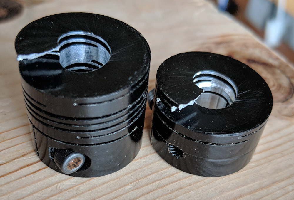
When I removed the old Z-axis stepper, I discovered that the coupler had cracked almost completely through. It only took a little axial bending for it to split into two pieces. It clearly would not have lasted much longer.
As I removed the steppers from the mill, I also discovered that the Rocom coupler that connects the Z-axis motor to the ballscrew had cracked and was close to splitting in two. This clearly is fatigue cracking and might be related to the fact that there is some wobble in the ballscrew thrust bearing, so there’s more flexing here than it should be. Crashing the machine into the workpiece and into the hardstops also probably haven’t helped…

This is the motor for the X-axis (the Y uses the same model). It is one of the smallest and cheapest Clearpath motors, the SDSK-2311S. This motor did not have enough torque for the Z-axis.
This wasn’t actually a big deal, because when I tested the motors on the Z-axis it became clear that they didn’t have enough torque to overcome the combined effect of the friction in the ways and the weight of the mill head, so I had to order a different motor that trades speed for torque. The larger motor also has a 0.375″ shaft as opposed to a 0.25″ one, so I would have had to get a new coupler in any case, even if the current one hadn’t cracked.
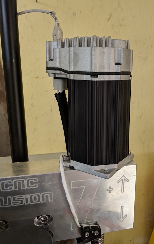
When I tested the XY motors on the Z-axis, it became clear that it needed a larger motor. This is the SDSK-2331S, which trades a lower max RPM for more than twice the torque (and more length.) It’s a bit more expensive, but not much. It also has a 0.375″ shaft, which required a new coupler.
I got the couplers with the CNC Fusion kit. They appear to no longer be in business, but I found you can order them directly from Rocom. However, buying a single one from them costs $100 compared to the ~$25 I paid CNC Fusion. Apparently they must have a large volume discount…
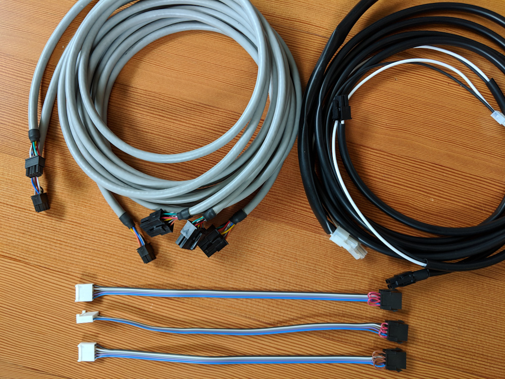
The servos do use a lot more complicated cabling than the steppers did, so there was a lot of connector crimping going on.
Once the electronics were done, I needed to make the cables. The motors use a 8-pin MiniFit connector for the signals and a 4-pin one for power. Then I needed internal cables to go from the board to the connector on the back of the box, too, so I ended up doing a lot of crimping.
The circuit board with all the connections hooked up. It’s quite busy inside there now.
Once I found a couple solder bridges on the circuit board, worked out some kinks with the Arduino code, and adjusted the motor settings in G2, it seems to run well. The servos really haul, I’m now running a max jerk setting that’s 4x what I ran with the steppers, and 50% more speed. The XY axes now traverse at 15000mm/min, while the Z-axis, with its lower speed motor, maxes out at 13000mm/min. I loaded up an old job just to see what it would look like:
The one thing I haven’t figured out yet is whether it’s possible to keep the position in case a motor shuts down. The fact that it’s shut down of course means that it’s no longer holding position, but the motors still keep track of their position commands and there’s a setting where they will return to their commanded position when they’re re-enabled. I haven’t tested this but, if it works as expected, it should be possible to move the other axes during feedhold to clear the spindle and re-enable the motor that shut down. It would then return to the position it should be and it might be possible to resume the job, which would be awesome.
Even if it’s not possible to resume the job, not losing position means that it can be canceled and restarted with suitable changes and the work coordinate system would still be valid. This is in contrast to the steppers where a lost position in practice means that you need to re-measure part zero. In principle, it would be sufficient to just re-home the axis, but the limit switches are only repeatable to something like +-0.2mm which usually is not good enough.
I’ll report back with how this works out once I’ve gotten some time on it, but for now this looks like a great upgrade.
Pingback: CNC mill upgrade: Spindle – Patrik's projects
Pingback: CNC mill upgrades: Couplers and gibs – Patrik's projects