In the post that talked about how I burned out the Arduino, I concluded with the need for a dedicated 48V-to-12V converter that would supply power to the Arduino but also to the coolant solenoid and various other things that might need 12V.
Unfortunately a switching buck converter is a bit more complicated than just wiring up an LM317, so it took me a little time to find a suitable component and then study the data sheet to come up with a design. I was going to use the LT1766 from Linear Technologies, but was having trouble getting clear guidance from their data sheet when I discovered that ST Electronics has a complete on-line design tool that allows you to input your specifications and pick components from a library. This was so user-friendly I just had to support them, so instead I ended up going with the L7987, a 61V 3A integrated regulator. 3A should be plenty (the air solenoid uses 0.5A).
With that design help, I started drawing the board in Eagle. I had two options, either make a small board just for the converter, or make a full-size shield for the Arduino Due. I decided to go with the second option, even though this would make the circuit board a lot more expensive, since that meant I could break out dedicated connectors for the motors, limit switches, LEDs, and so on. This would be a lot better than having anonymous headers where you have to remember what goes where. It would also save me the hassle of mounting a tiny board somewhere in the box.
Apart from the layout of the switching regulator, which is somewhat critical because of the high frequencies involved, it was a simple matter of just getting the correct TinyG pins wired to the various connectors. I wanted polarized connectors, so I got a bunch of Molex KK254 ones of various lengths.
With the design completed, it was just a matter of uploading it to OSH Park and wait. It was actually fairly quick, total turnaround from upload to getting the boards in the mail was less than two weeks. I also got a new Arduino Due from “SainSmart”. The solder job on it looked a lot better than the one on the $15 “Chinarduino” even if it was eight bucks more. The circuit boards cost something like $30 for 3 and are really high quality.
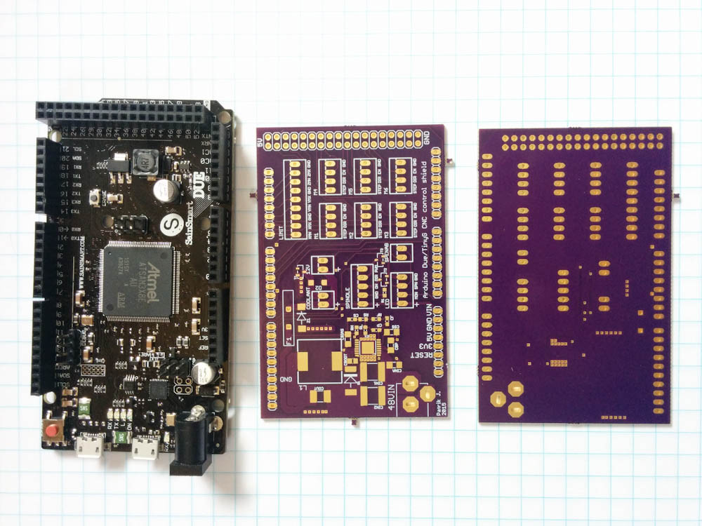
Here’s the black “SainSmart” Arduino Due clone along with the purple PCB for the shield from OSH Park.
I’ve hand soldered surface-mount components before, but the L7987 would be a new challenge. Like most of the voltage converters that can handle reasonably high currents, it has a large exposed pad on the bottom that needs to be soldered to a ground plane for heat dissipation. This presents somewhat of a problem for hand soldering since you can’t get to it. They’re meant to be reflow-soldered where solder paste is applied to the pads and the whole board then heated up so the solder paste melts. This takes some specialized equipment, but apparently it’s possible to do with the help of a hot air gun and an IR thermometer, too. So I decided to go for it.
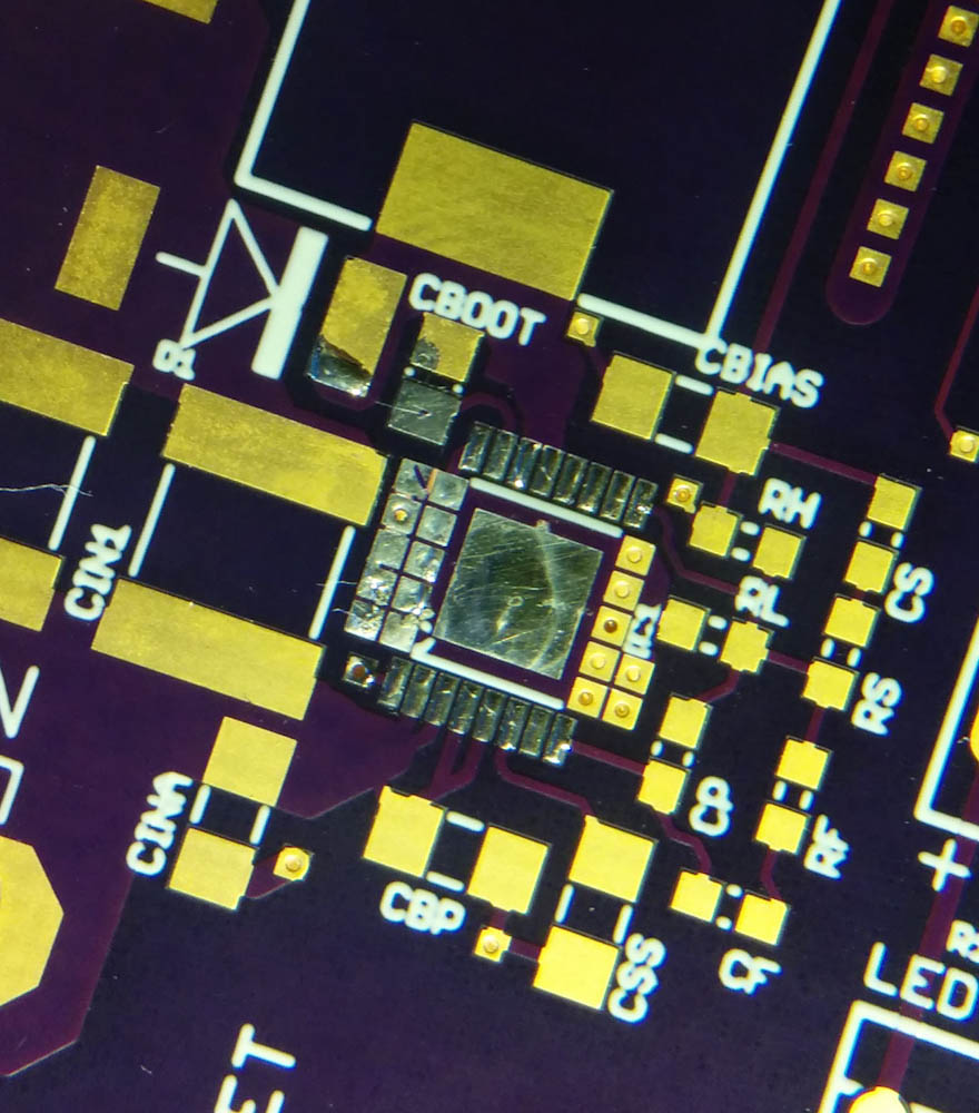
First step is to tin the pads where the L7987 is supposed to go. The large square is the thermal pad that connects to the PCB ground plane on the opposite side of the board through the large numbers of vias on either side. The more connections to the back side, the better the thermal conductivity.
After tinning the pads, I applied flux and carefully placed the chip on the board and started heating. The recommended heat profile is something like 1-2 minutes at 150C (to pre-heat the components) and then 30-60 seconds to go up to 260C and back down to 150C, so with the IR thermometer and a timer, I adjusted the distance of the hot air gun to keep the board at the recommended temperature. After the pre-heat, I went in and focused the heat on the chip until I got up to 260C+, and then quickly back down again. It actually worked really well.
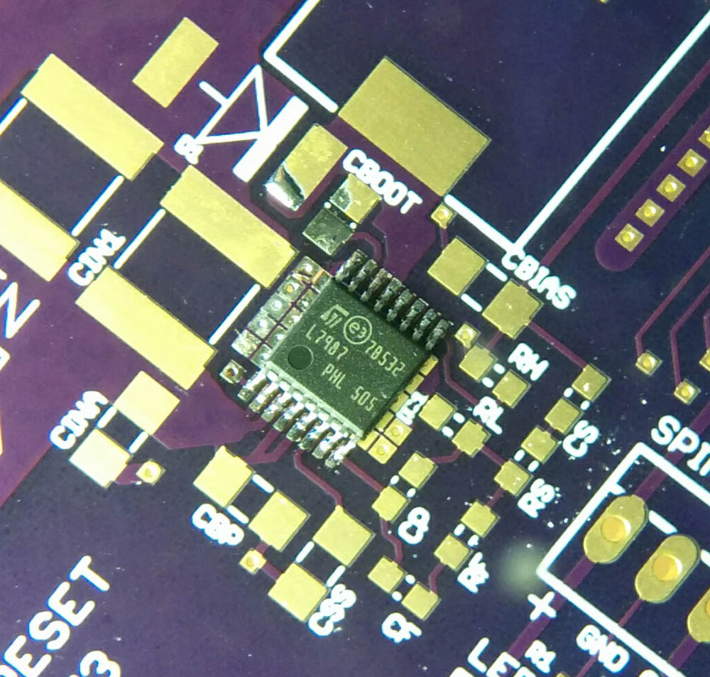
This is the L7987 after the hot air gun session. It worked really well. Note that the tin on the vias have also flowed into them, which should improve the thermal conductivity further. For reference, the size of the chip is about 5mm square.
With the hardest part done, it was just a matter of putting all the remaining components in place, not hard but somewhat time consuming. I hit a small snafu when I realized that I had neglected to get a 0.1uF capacitor (for “CBOOT” in the picture above). I have a bunch of 0.1uF caps but they are 25V and I realized (luckily before trying it) that those caps see the full input voltage, so the completion of the circuit was put on hold until I could get a few 100V ones from Mouser.
Another small snafu was that I realized I couldn’t hand solder the big 47uH inductor either, so I had to pull out the hot air gun once more. This was a bit more tricky because the inductor has so much mass that it heated up much more slowly than the rest of the board, but I got that done without overheating the rest of the board, too.
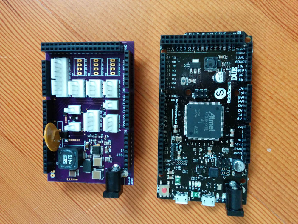
This is the completed shield along with the Arduino. All the white KK254 connectors and their pins are labeled. I didn’t bother soldering in the connectors for motors 4-6 now, since I’m not going to use them.
The shield has a DC plug for the 48V input. In the interest of circuit protection, it also has a 4A polyfuse (the big brown disk) and a 16V Zener diode. In case the converter malfunctions and shorts the input to the output, the zener will shunt the excess voltage to ground and the polyfuse will interrupt the circuit (hopefully fast enough that the zener diode doesn’t vaporize…). The 12V output from the converter feeds the coolant output, an always-on 12V power out, and the Arduino through the Vin pin.
One thing I realized I forgot to put in the schematic was a blocking diode that prevents power from backfeeding from the Arduino into the shield if the Arduino is powered but the shield is not. I hacked this in by cutting the trace to the Vin pin and soldering a diode between the pins on the back of the board.
After the previous mishap, it was with some trepidation that I powered up the voltage converter, but it seems to work perfectly well. I haven’t really tried to pull the full 3A out of it yet, but it did 1A from a 30V input with essentially perfect regulation. Hooked up to the full 48V input, it still worked perfectly.
Eager to test it out, I mounted the shield to the new Arduino and wired up the new motor connections. It sure looks a lot better than before. That’s when things went south.
If you look at the pictures above, you will notice that both the shield and the Arduino have a DC power connector… Clearly the 48V supply is supposed to be plugged into the voltage converter on the shield, not the 16V max Arduino power input. However, that’s exactly what I, in what can not be described as anything but a brief lapse of brain function, did. Hence, when the power was turned on, there was yet another puff of smoke and the voltage regulator on the brand new Arduino was history.
I don’t know how to explain this. All I can say is that after a full day of working on a bunch of different things I did not follow the rule of “always double check the power connections before turning power on”. Oh well, these are the kinds of mistakes that make you learn. Hopefully. At least I had added that blocking diode on the shield so the 48V didn’t backfeed to those circuits. I don’t think that 16V Zener would have been too happy about that with no polyfuse to protect it.
Amazingly, this Arduino seems to have survived, too. They’re apparently more rugged than you give them credit for. The voltage regulator is toast, but I’ll get a new one and solder it back in. One trace was burned off, too, so I’ll have to make a little jumper. Maybe it’ll be fine.
But just in case, I have yet another Arduino on order. Let’s hope that’s the last.
P.S. As I mentioned, I got three circuit boards. I don’t anticipate needing more than one, so if someone else is wiring up a TinyG motor controller and wants one of these shields, let me know.
Pingback: CNC Mini Mill #7: Another kind of shield | Patrik's projects
Pingback: CNC mill upgrade: servos – Patrik's projects