I finally got the engine case back from the machine shop, so I could proceed with remaining work.
First I finished up drilling out all the oil passage plugs from the case that my Dad and I started before giving the case to the shop. To be 100% sure that you get all gunk and swarf out of the oil passages, you need to remove all the plugs from the case and instead tap them with assorted NPT pipe threads so they can be replaced with screw plugs at assembly.
This task was straightforward except that the largest passages use 14mm plugs that need to be drilled out and tapped for 3/8″ NPT thread. The drill for such a tap is just over 14mm, and the only place I can mount such a drill is in the drill chuck for the CNC mill. The CNC mill, however, doesn’t have enough space to fit the engine case, so that was not a solution. I ended up using the Dremel to get rid of most of the material from the inside of the existing hole (always fun) and then turning the drill bit by hand to let it cut the hole to size. It took about 20 times longer than if I had been able to just drill it, and the holes did not come out perfectly perpendicular. That is luckily not a concern since all you need is for the tap to cut a usable thread, which it did.
The Dremel added to the significant amount of swarf still left in the case from the machine shop cutting it for the prop hub bearing, but I only cleaned it out superficially since I still have one more drilling operation to complete. I need to drill out an oil passage to improve oil flow to the heads, but that task awaits the arrival of a 12″ long drill bit.
Instead, it was time to test fit the crankshaft and make sure the machine shop hadn’t screwed up the job. The first order of business was to make sure everything was in-line and the crankshaft wouldn’t bind in the bearings. Before fitting the crankshaft, I started by bolting together the case halves and measured the bearing bores with my just-acquired cheap set of bore gauges. These require a bit of skill to use accurately, but in combination with the Mitutoyo digital caliper the bores generally came out to 50.03mm, plus minus a few hundreds of a mm. That’s in the right ballpark, since the service limit turns out to be 50.03mm, but the as-new dimension is 50.00-50.02mm so I don’t really have the required amount of precision here. But at least there was no sign that the bores are grossly oval or oversized, so that’s good.
When trial fitting the crank, you replace the locating dowel pins, mount the #2 bearing half (the other bearings are full-rounds so are slid onto the crankshaft) and then lower the crank in place, taking care that all the bearings find their dowel pins correctly. At that point, the crank should spin freely. Which it did, kinda. Not as freely as I would have hoped, but only finger force was needed.
The real test is to do this with the case halves bolted together, though, because the stud tension actually deforms the case. Boring is always done with the case bolted together to the correct torque, so in principle the bearing bores aren’t circular until things are tightened down. This actually turned out to be the case now; as the studs were tightened the crank spun progressively more freely. Kind of cool. This included the new Force One bearing, so apparently the machine shop did their job.
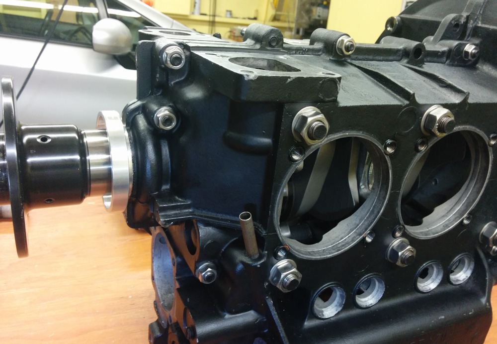
The engine case with the new Force One bearing up front, bolted up and with crank and cam shafts test fit.
The next step was to add the camshaft. Here things looked a bit more iffy. First, the gear driving the camshaft has a lot of scoring on the teeth. I assume this also is from all the particles embedded in the oil.
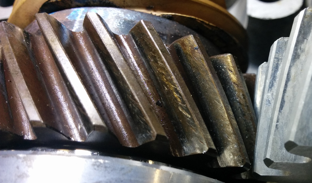
The gear driving the camshaft has some knarly looking wear and scoring. However, it does not have excessive backlash so it seems OK.
The second problem was that when I added the camshaft in its bearings and tried to spin it, it would bind at a few places. Turns out that a few teeth had gotten dented on the edge. I suspect the shop did this when they pressed the gears off the old crankshaft. To get things to rotate smoothly, I had to dress the affected teeth with a file. No big deal.
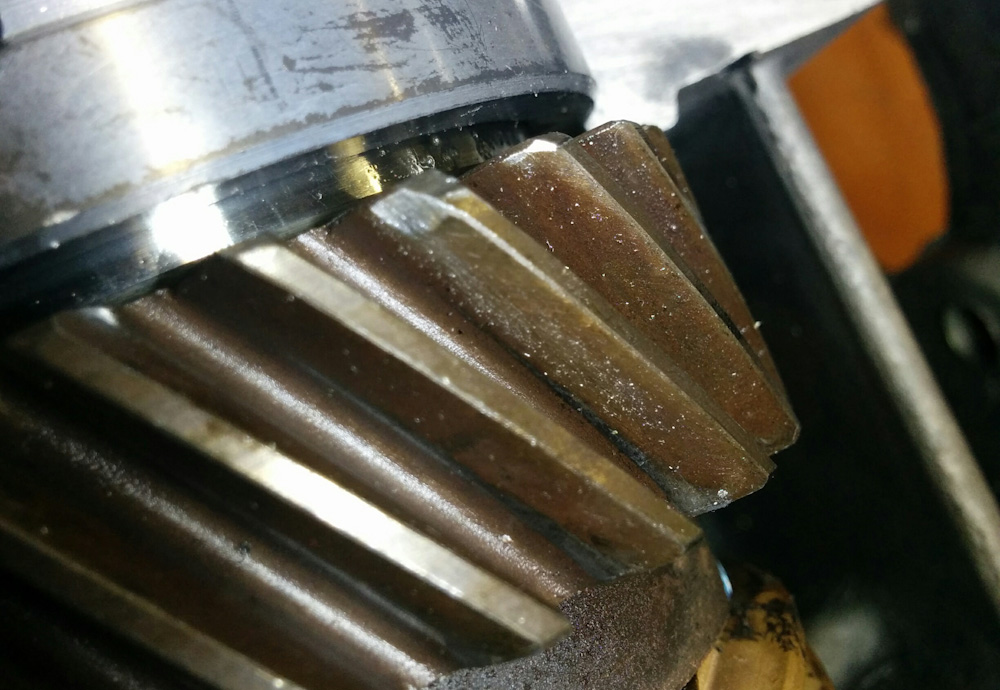
A few of the teeth on the cam driving gear were banged up such that it would bind against the cam gear. Minor dressing with a file got the raised parts back in line so the gears meshed cleanly again.
Another little thing I was alerted to by a youtube video was the fact that the thrust bearing’s oil supply hole is not very well aligned with the oil passage in the back of the bearing, such that about half the oil supply hole is blocked. The solution to this is to simply grind away the back of the bearing to open up the hole.
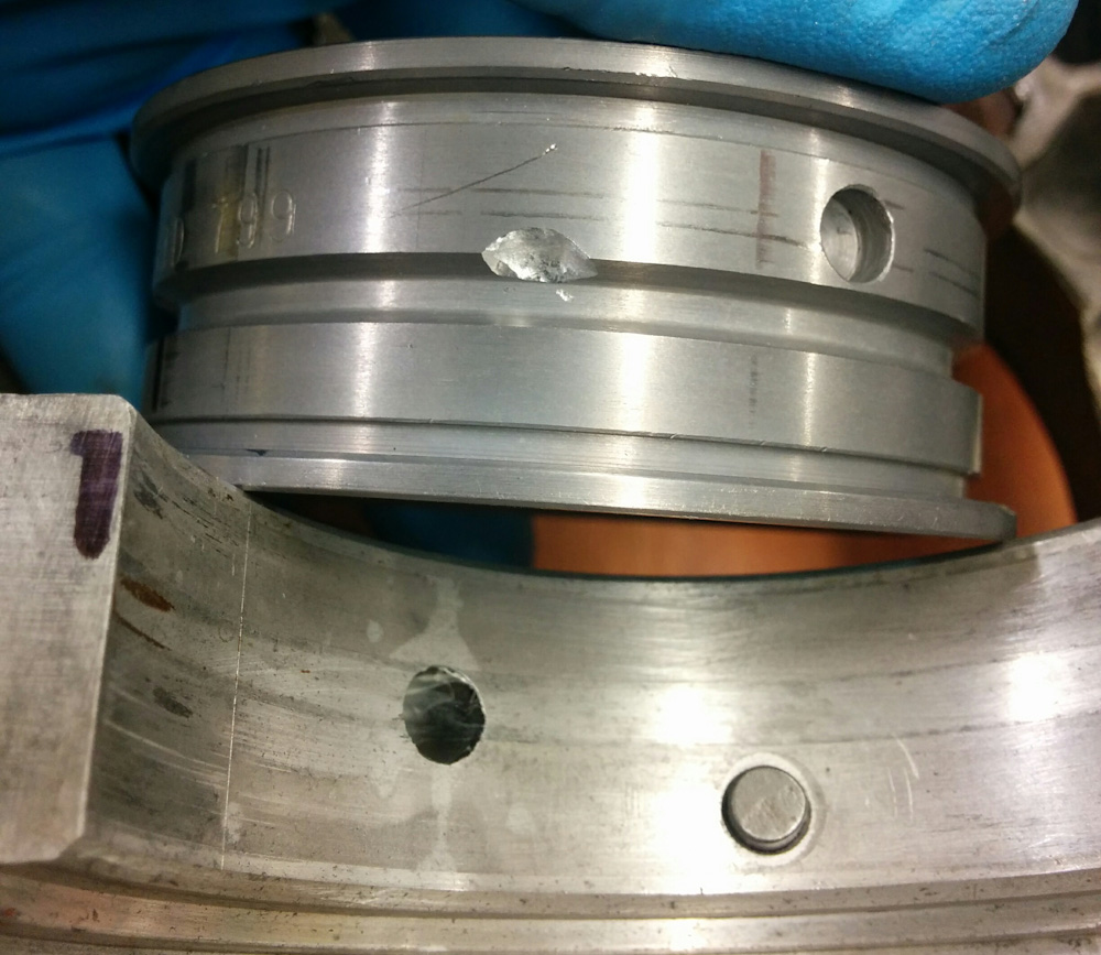
As is visible on the thrust bearing journal, the supply hole is offset from the circular groove on the back of the thrust bearing. By grinding away the back of the bearing where the hole enters, the obstruction is minimized.
There are a few more things to sort out with these bearings. There is still a little binding when rotating the crankshaft/camshaft in the assembled case. It’s possible there’s another buggered tooth on the gear that I didn’t notice before. It’s also possible that this is because the thrust bearing on the camshaft has no end play. This is apparently a common problem with the bearings you get these days; they’re all too wide such that they actually stick on the camshaft. The solution is to carefully sand down the thrust surfaces of the bearing halves until the requisite 0.04-0.10mm appears. If you don’t do this, the bearing will not get sufficient lubrication.
Once these issues are worked out, it’s time for the rod bearings. Hopefully before the weekend.
Pingback: Engine guts 4: Blueprinting – Patrik's projects
Pingback: Engine guts 6: More head work – Patrik's projects
Pingback: Engine restart – Patrik's projects
Patrik, Where did you find the dimensional value to machine your cases to fit the Force One Bearing? Or, what diameter did you machine the cases to fit the 2.2992″ OD Force One Bearing?
Oh boy, I can’t remember. I believe it was in the instructions that came with the crankshaft, but I may be mistaken. I certainly don’t remember the actual diameter. If you call Great Plains I assume they would be able to help you.