In the last post, I outlined the change to swap out the leaky clamp joints on the exhaust header pipes for double slip joints and got as far as cutting the old clamps off the exhaust.
I’ve watched a couple of videos on fabricating exhaust systems and they all make the point that the fit up needs to be exact. Any gaps in the joints to be welded drastically increases the risk of blow-through as well as makes the part warp more. Then they make a bunch of pieces, fast forward, and weld everything up. Well, it turns out that fast-forwarded part takes a long time. Everything needs to be aligned precisely for the slip joints to work, both the position and the angle needs to be correct. This is actually a tricky problem, because changing the position, by rotating a joint, also changes the angle, and vice versa.
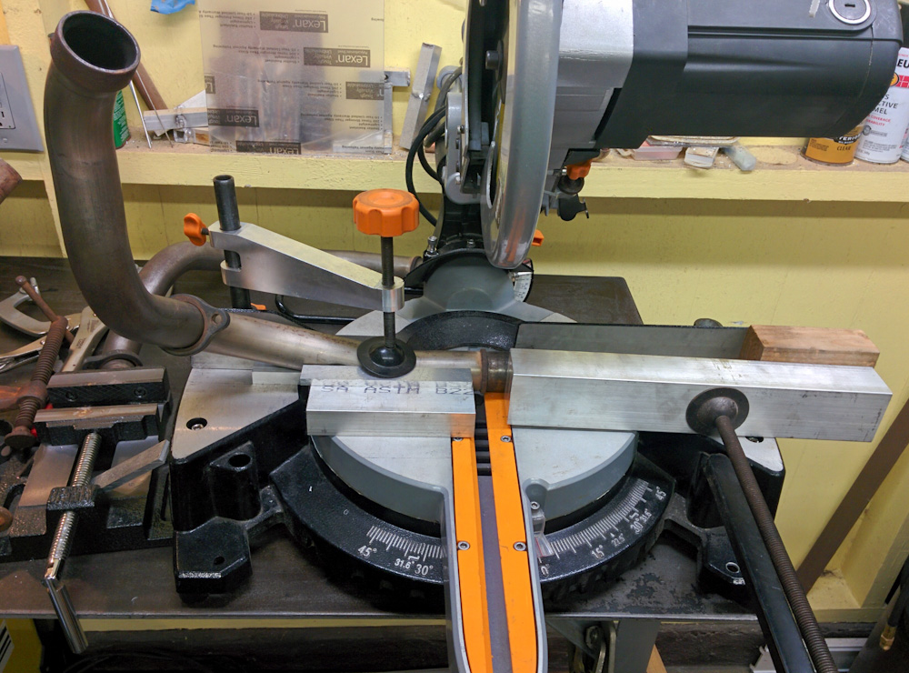
Suffice to say, I spent a whole day tweaking two short lengths of header pipe, aligning joints by grinding on the surface until it was right, then making sure there’s even contact all around. People seem to use stationary belt sanders for this, but even our tiny belt sander from Home Depot actually was helpful in getting a perfectly flat surface.
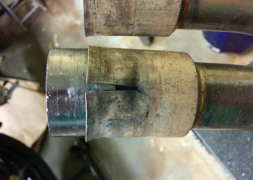
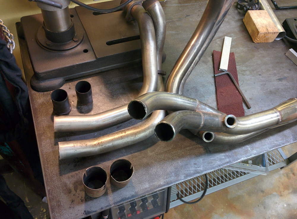
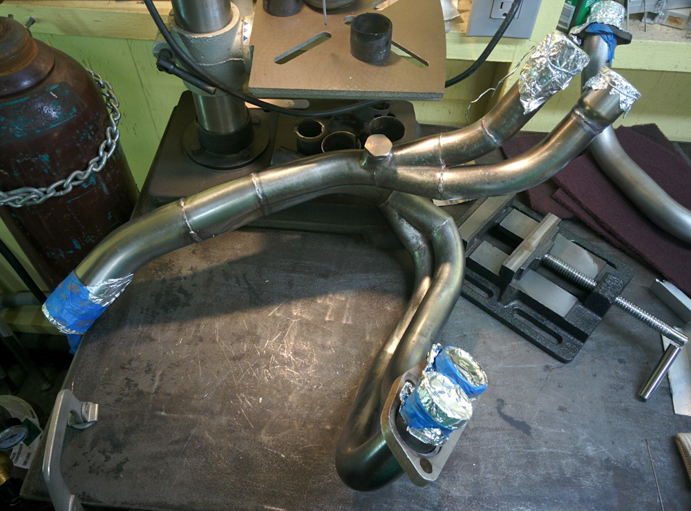
In the end I had something that looked like it would work, so I tacked it all together for a trial fit. To get the angle right to cylinder 2 (front left) I had to cut the collector end and rearrange the bend a bit. Before, both the pipes coming out of the collector going forward were angled downwards. The right one wasn’t too bad, but the only way to avoid a sharp kink in the left one was to cut the bend near the collector and rotate it to a more horizontal angle.
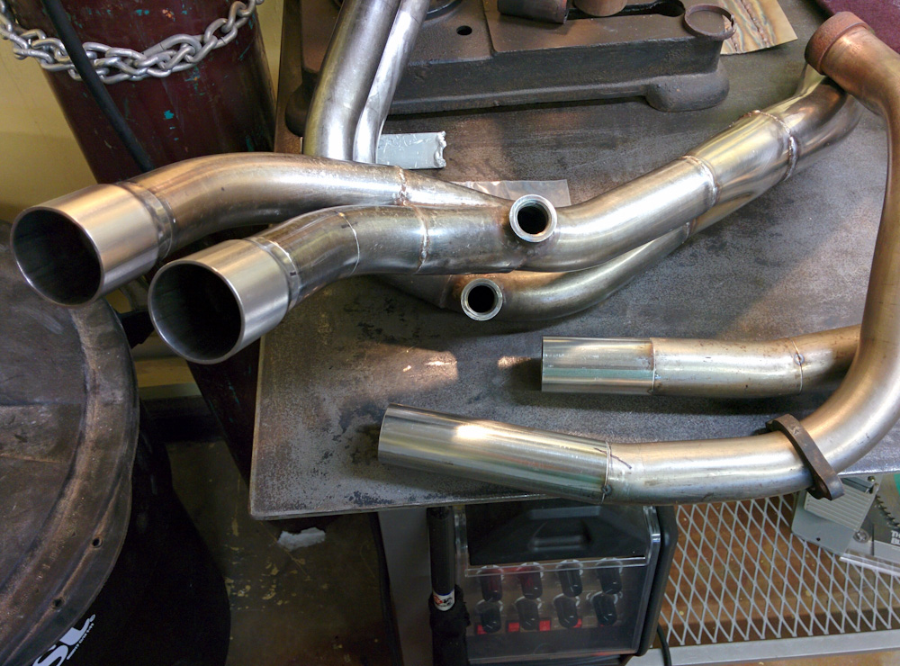
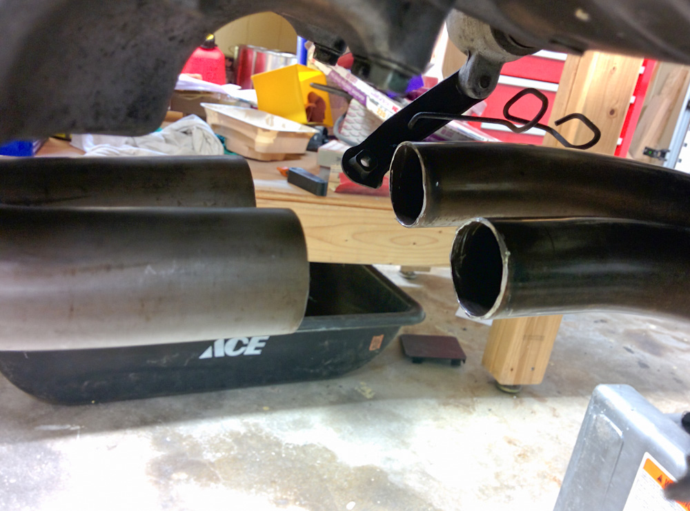
The pieces have been tack welded together and are ready for a trial fit. Note the extra joint that was cut in the right pipe coming out of the collector. This made it possible to rotate the bend and aim it less downwards. The outer parts of the double-slips have not yet been attached to the headers.
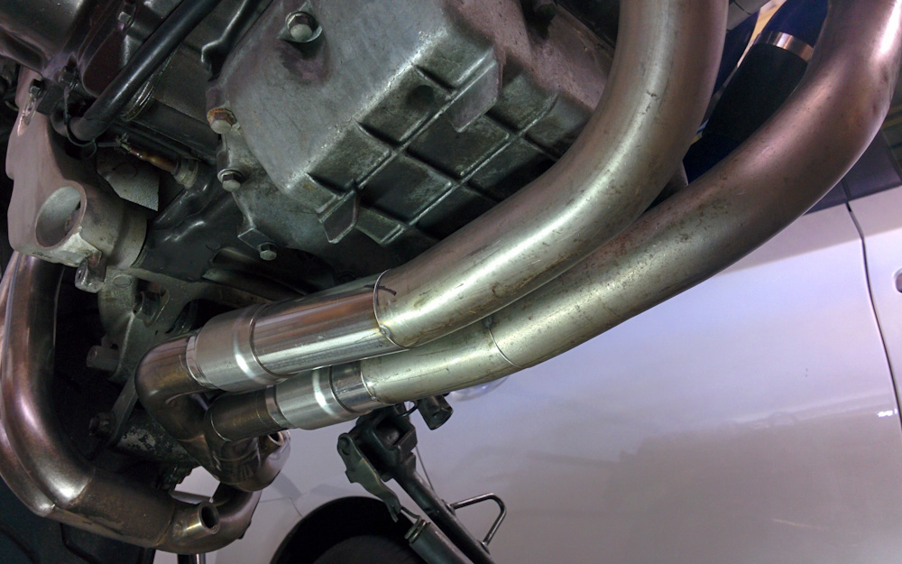
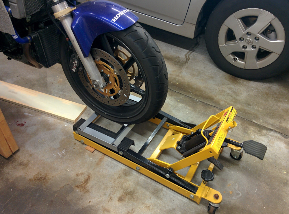
The pieces successfully fit together on the bike, so that was nice.
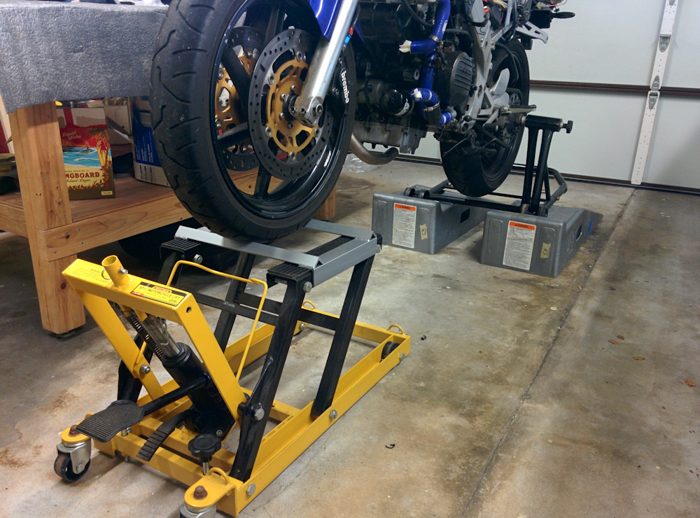
As you can see, the headers aren’t perfectly parallel with each other under the bike. It’s not visible, in any case.
Since everything fit, there was no reason to postpone welding it all together. Based on some tips on the Burns Stainless web page, I used 0.035″ 308 filler rod and about 37A. I had made some practice welds on a piece of spare tubing I got for that purpose, and that went reasonably well.
Welding stainless is kind of cool, because of its low thermal conductivity it doesn’t immediately get all hot like aluminum does, and you can use low current and get a small puddle. It’s important to not use too much heat when welding stainless, it will darken and discolor and this also makes it more prone to oxidation later. If you manage to use the minimum amount of heat, the weld will have a nice, golden color.
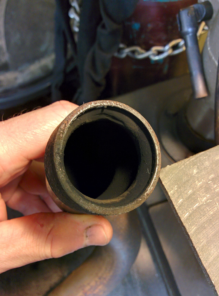
Just like when I welded on the oxygen sensor bungs, I had to set up an Argon purge to get all the oxygen out from the inside of the pipes. If you don’t do this, you get huge balls of oxides protruding out from the inside of the weld, and the weld will be weak. This was kind of a pain, because the whole exhaust system is kind of large and unwieldy and has a tendency to roll around on you. The situation isn’t improved when you then add a ground clamp and the purge gas hose.
To purge the air out of the pipe, i attached the Argon hose to the large end and sealed up all four end with aluminum foil. To weld the headers, I simply removed one of the foil caps over the slip joints and slid the header pipe on. This was actually a lot easier because I could rotate the header in the slip joint as I welded around it.
It’s a bit stressful to hear the hiss of your precious Argon being continuously vented into the pipes as you struggle to find a good position, have to re-grind your tungsten, have to re-adjust your glasses, etc, etc. In the end I used about half of the little 60-bottle I got for doing purges. That’s about $50 in Argon right there.
It took a while, but there were no welding disasters. The worst part was when I started welding one of the slip joints to the collector and realized after having welded maybe an inch that the tacks had given out and the joint had opened up about a millimeter. I considered grinding off the weld and starting over, but I managed to clamp the joint back together and re-tack it. That’s probably not ideal and it’s possible this deformed the joint enough to matter, but it seems OK for now.
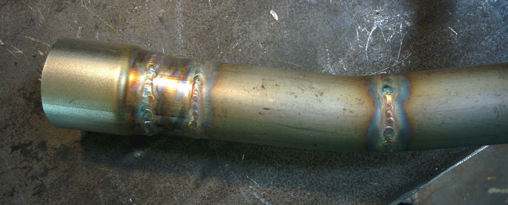
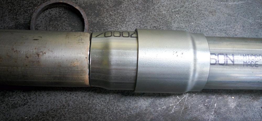
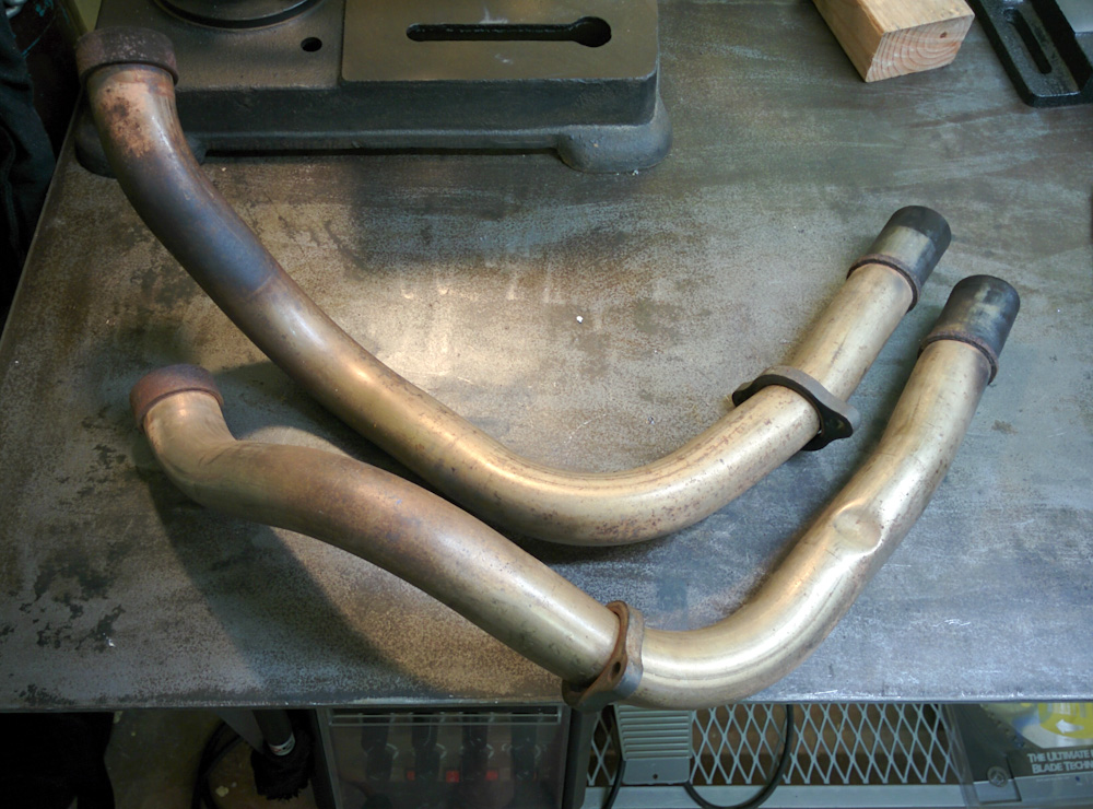
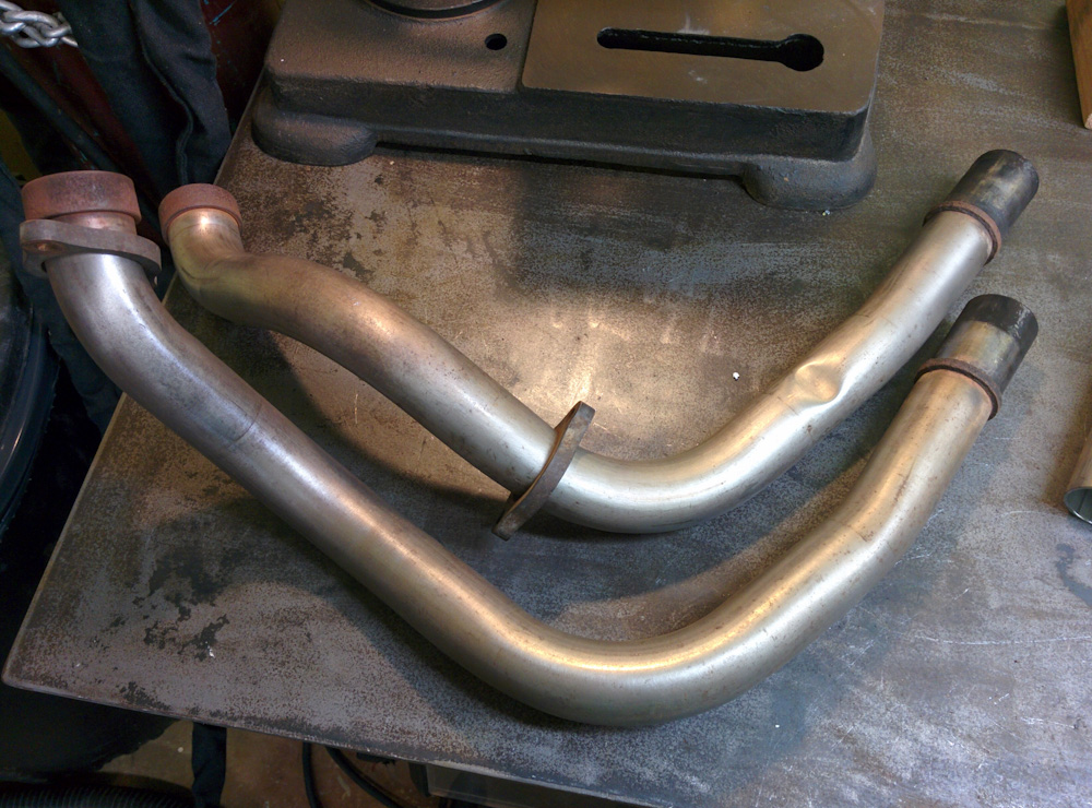
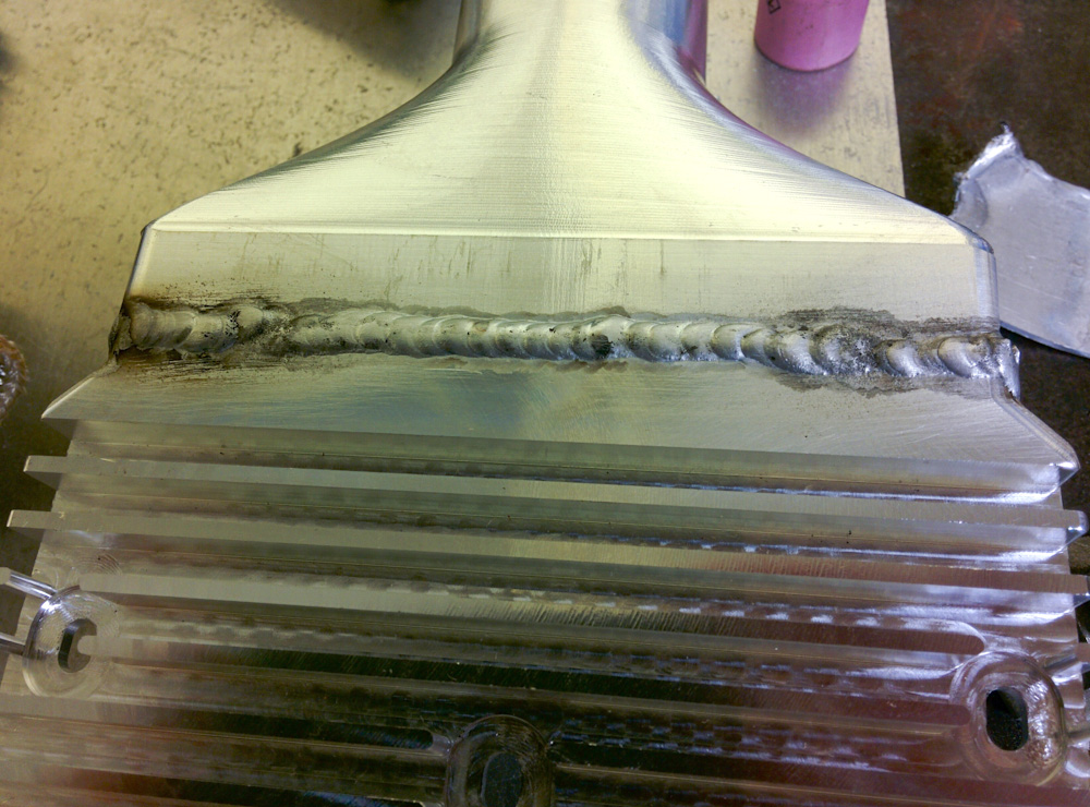
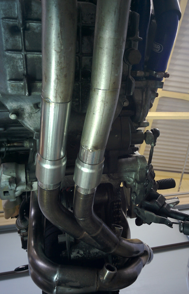
One of the headers after welding.
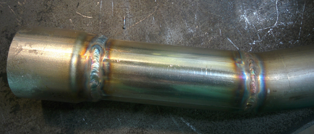
And the other. The welds aren’t stellar, but I’m pretty happy with how they came out.
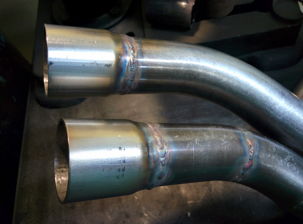
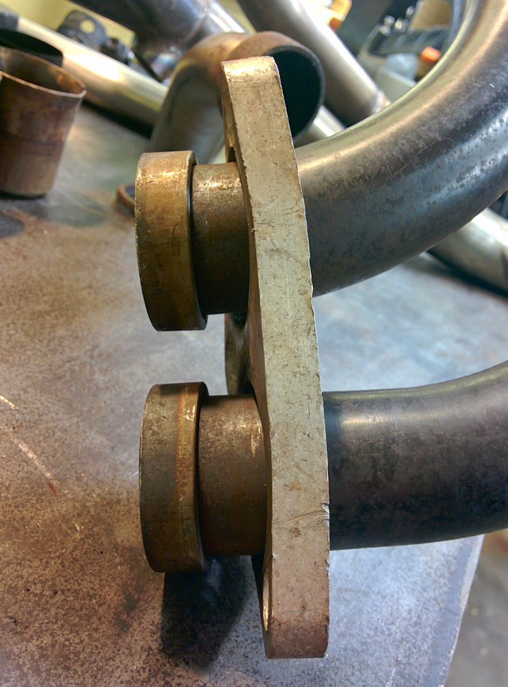
And finally the collector end.
After letting everything cool down I was anxious to see if it would still fit together or if something had shifted. There was definitely more resistance now, especially in getting the slip joints to slide into each other. Any misalignment definitely makes them want to bind, but by putting everything in place first and then gradually tightening all the nuts, it came together. When the engine is started I guess we’ll really see whether there are any leaks, but by blowing into the muffler end of the exhaust system I could test that, after tightening all the nuts, the only place I could note air coming out was in the slip joints.
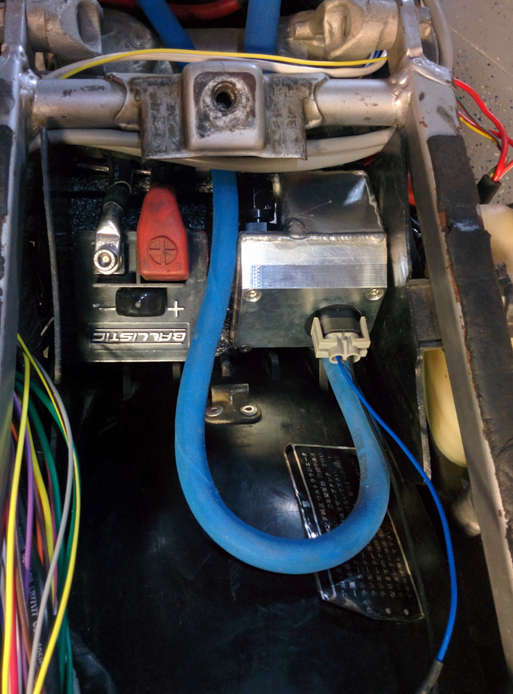
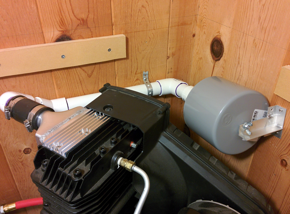
Now I’m just waiting for one more fitting and then I should be able to hook up the tank to the fuel pump and see if it starts!