The last post ended without holes to mount the idle air control valve. This turned out to not be a big deal. There’s a raised edge around the entire airbox casting that I could rest it on while clamping it to the mill table.
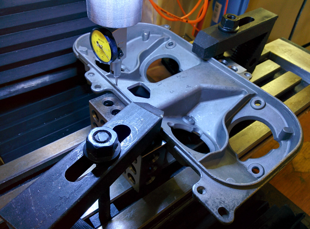
Fixturing the air box casting to the mill table turned out to not be a problem. I rested the outer edge on two 123 blocks and clamped it down. I’m not sure this would have been good enough for milling, which causes a side load, but for drilling it worked fine. At this point, I’m checking that the airbox is square to the table by running the dial test indicator against the edge.
With the holes drilled and tapped, the valve fit perfectly.
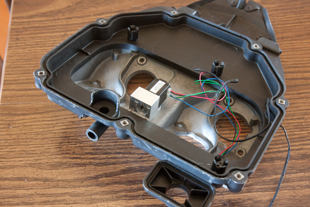
The IAC valve fits exactly like it should. There’s maybe a mm of clearance to the inner edge of the plastic frame, and the valve is lower than the intake trumpets so it won’t hit the air filter.
The next step was to route the hoses to the intake ports on the throttle bodies.
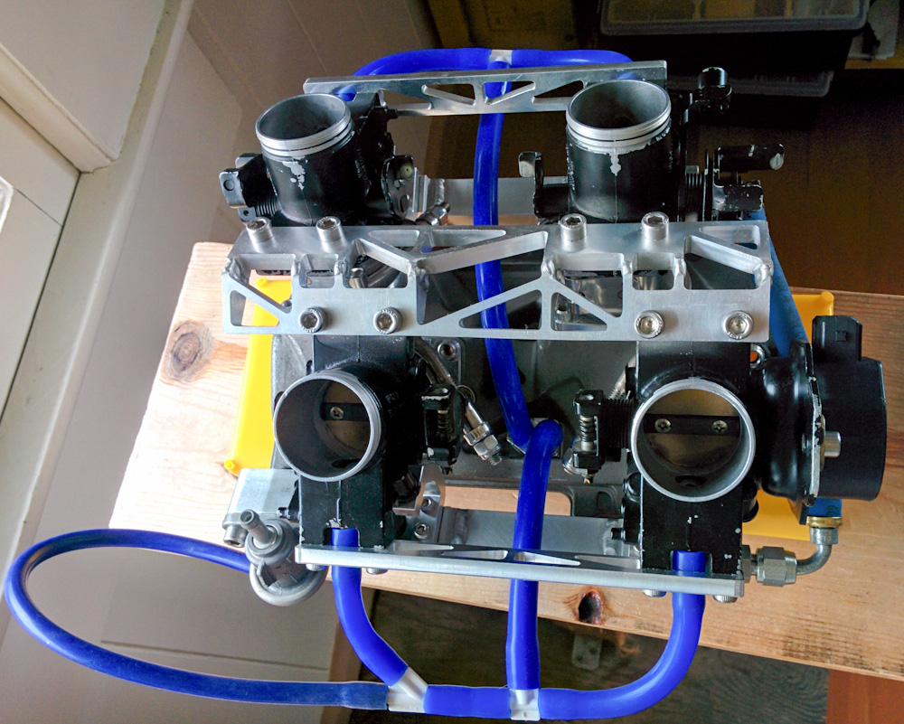
The air connections are made with a 5mm ID silicone hose from the IAC valve body to a T on each side. From the split, 4mm ID hoses go to the two throttle bodies. One side has an additional split for the connection to the fuel pressure regulator pressure reference. (That hose has not yet been cut in this picture.)
Trial fitting the intake assembly on the engine, everything looks good. It’s probably going to be necessary to support the hoses with a few clamps, but I’ll deal with that when everything’s working.
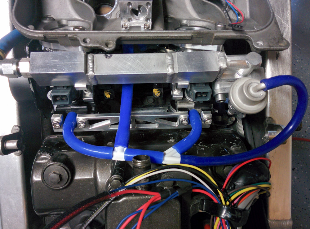
Test-fitting the intake assembly. The idle air hoses appear to clear all the possibly interfering parts.
That completes the mechanical part of the idle air control. The one remaining thing is to wire the stepper motor up. I’m not 100% sure how to do this, I think I’ll need two connectors, one inside the airbox so you can remove the stepper, and one on the outside so you can disconnect it for removing the airbox. I’ve been using “Mizu-P25” connectors from Molex for other things on the bike so I’ll probably use them here, too. I’m very happy with them, they’re waterproof, small (2.5mm spacing), handle up to 4A, are easy to crimp and plug/unplug and are relatively cheap (like $8 for all the parts for one connection).
To avoid having the electrically noisy stepper motor interfere with other sensor wiring, I’m using a 22AWG 2-pair shielded wire. The stepper motor only runs 150mA so 22AWG should be plenty.
I also tweaked the software side a bit. The trouble was the homing, which was trickier than I first anticipated. The idea is that there is a hard stop on the valve and at powerup the controller will run the motor far enough that it can be assured it’s against the stop. It can then be initialized to the known position. You can see this in action in the very short video clip below.
When I initially tried this, the repeatability of the valve position after homing was not good. After a bit of thinking I figured out what’s going on:
When the motor runs into the hard stop, it’s unable to follow the magnetic field and will “slip” back to its next equilibrium position. This will happen at a specific switch of the motor phases (if you’re unfamiliar with how stepper motors work, check out Wikipedia). At full-step operation, a stepper motor can be in one of four states, let’s call them 00, 01, 10, 11 (indicating the direction of the current in the two phases). In each of these states, the rotor will be at a specific angle and each move from one state to the next moves the shaft by 1/200 revalution. This means the pattern repeats 50 times for one full rotation. Now say the motor hits the hard stop when going from the 10 to 11 state (this will always be the same as long as nothing moves mechanically.) It will then move back 4 steps (1/50 of a revolution) to the previous 11 position.
With that background, the problem should be clear: the stepper driver is stateful. While to the outside, it just moves the motor one step every time it gets a step pulse, it has an internal state machine that moves through the four motor states. (If the driver operates in microsteps, the number of internal steps are larger but the principle is still the same.)
Since the homing sequence just sends a fixed number of steps N to the driver, the final position of the motor depends on where it started. In the above example, if it happens to be in a position such that stepping N steps in the homing direction puts it in state 10, the motor will be very close to the hard stop. If it was one step closer to the home position, however, it’ll end up in 11 which causes the rotor to slip back 4 steps. The final position can be any of the 4 states. This is significant, since the range from the valve being fully closed to fully open is only about 45 full steps.
The only way to know what state the stepper driver is in is to reset it. Had I thought about this I would have wired up the reset line so it could be controlled by the Arduino, but I’m not about to solder any more wires onto that chip. It should be fine, however, because in normal operation it will only home at power-up which is also when the stepper driver is in a known state. It was just during testing the homing that I was resetting the Arduino, but that leaves the stepper driver in an unknown configuration.
I’m currently running the stepper in quad-step mode, but I wired up the microstep selection to the Arduino so it can do the homing in full step mode. If everything is perfectly rigid, it shouldn’t matter, but the smaller the steps, the smaller the margin between the step that pushes the rotor against the stop and the next one that makes it slip a step. Using full steps should make the process more robust.
Pingback: Microsquirting the NC30, part #30: Finishing up the airbox work – Patrik's projects