While slowly making progress on assembling the fuel pump housing (welding the 1.6mm 6061 sheets is really taxing my welding skills), I’ve addressed the other end of the fuel supply. The stock petcock can’t be used since it has no provision for a fuel return line, and the tall strainer makes the pump suck air long before the tank is empty. (This isn’t an issue with the carbs since they use fuel very slowly, but since the pump circulates the fuel it’s pulling much more fuel through the intake.) A new way of connecting the fuel lines had to be worked out.
I decided to simply make a small “connecting block” for the fuel supply and return lines, replacing the petcock. It doesn’t have any way of turning the fuel off (or a reserve) but that’s OK because it’s quite bad for the pump to try to pull against a closed tap. Having a reserve won’t work because that would make the pump draw air, and that’s also bad for it. (Not to mention that it’s not clear how hard it will be to get all the air out of the fuel lines.) The big drawback is that you lose any way of knowing how much gas you have in the tank.
I briefly considered trying to add a capacitive fuel level sender, but decided against it. With the amount of use this bike is likely to get, it won’t be a huge hassle to simply monitor your mileage and avoid running out. (Famous last words…)
As usual, there’s not a lot of space to work with. The fuel supply line has to run rearward from the tank, under the frame cross member, and into the fuel pump housing. If the attachment on the tank is reasonably close to the tank bottom, this line will slope downward the entire way to the pump housing, so the air in the line should be able to flow back up to the tank.
I actually designed the piece a while ago, before my parents visited, and I attempted to machine it a couple of weeks ago. Everything went fine until the last setup (it has to be cut from 4 different sides) when I apparently mis-typed the part origin and ruined it. This soured me on the part for a while (and I had plenty of cabinet doors to work on) but this weekend I decided that it was time to just get it over with. This time the machining went better.
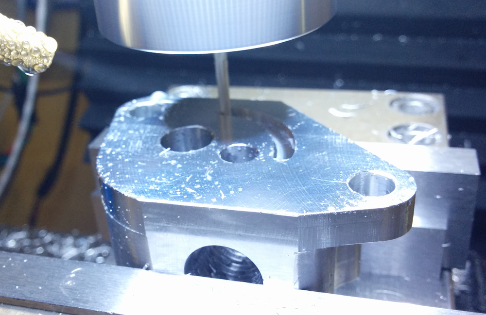
Here, the groove for the O-ring that will seal against the tank is being cut.
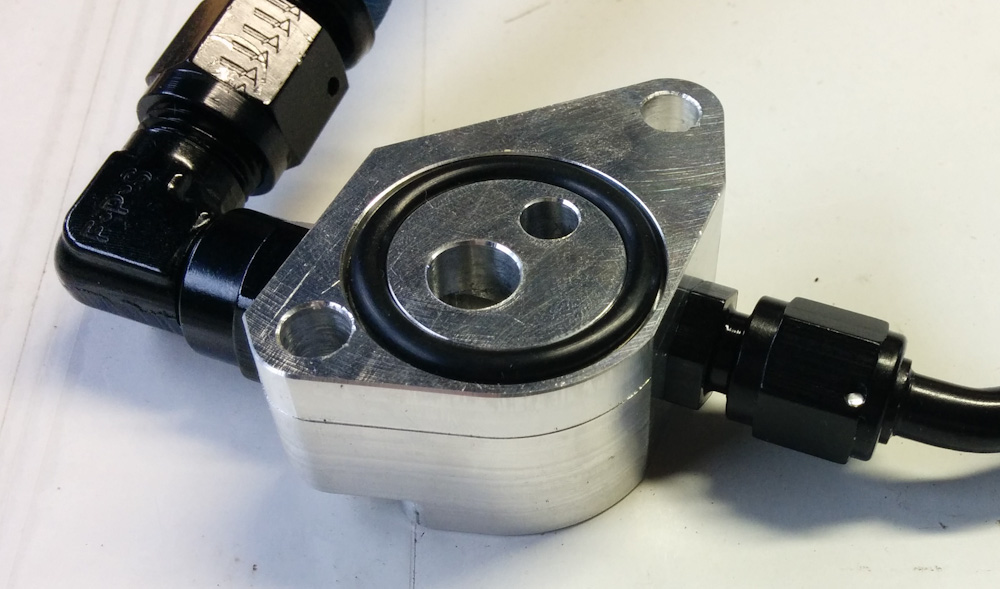
The finished petcock replacement, with the AN-6 outlet and the 90-degree swivel fitting on the left. The AN-4 return line is to the right.
Since the fuel line will go basically straight rearward, it would be very difficult to remove and replace the tank with a hard hose fitting due to the hose needing to go under the frame cross member. It would require a very sharp bend to get it under when mounting the tank, and the minimum bending radius on the AN-6 hose is something like 3 inches. So, instead of pointing the outlet directly rearward, it’s to the side. This makes it possible to attach the hose to a 90-degree swivel fitting as seen in the picture above. This way the fitting can swivel to point the fuel line down when the tank is raised.
The fuel return line is a bit easier to deal with, apart from the fact that it is very tight going forward under the tank from the petcock area. Using a 45-degree hose end, it will run forward under the tank lip on the right side and then somehow loop around and attach to the fuel pressure regulator return line. It may be easiest for it to do a 270-degree turn around the forward fuel rail, down and back, and then to the FPR.
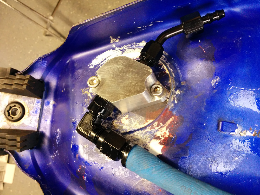
The petcock replacement block mounted on the tank. The outlet is twisted 180 degrees here from how it will run when mounted. Note that the outlets on the block are rotated slightly from the side-to-side direction. This allows the outlet to run laterally to meet up with the fitting on the fuel pump housing and the return line to run parallel to the tank edge when using a 45-degree fitting.
I’m not sure whether the O-ring will seal against the underside of the tank given the partially remaining multiple layers of paint you can see in the picture. I may have to sand it smooth. That paint all has to come off eventually anyway as the plan is to repaint it.
The fuel system is slowly coming together. Now if I could just manage to weld the fuel pump housing together…
Good to see (a post that shows) you’re back at the NC30 project.
I don’t have your skills or equipment so for my Petcock replacement I used the Pingle Fuel Injection Manifold. They sell various adaptor plates for different bolt spacing on OEM fuel tanks. Both my projects, the Kawasaki EX-250 and the Suzuki GSF-400 are running the Pingle manifold. Don’t know why Pingle chose the angle between the outflow and inflow hose barbs, on one of my bikes it was the perfect angle for the job while on the other it was/is a bit of a nightmare.
https://catalog.zodiac.nl/en/catalog/19-tanks-dashes-tacho-and-speedo-meters/tanks-dashes-tacho-and-speedo-meters/petcock-fuel-valves-/pingel-fuel-injection-conversion/
Good to see you back at work on the bike, looking forward to seeing it back on the roads.
Yeah, I got side tracked by some stuff but I’m still working on it. Look for a post about the idle air control soon… 😉
Pingback: Microsquirting the NC30, part #31: Finishing up the fuel pump housing – Patrik's projects
Pingback: Microsquirting the NC30, part #35: Fuel supply line – Patrik's projects