In the previous post, I described my solution for controlling the idle speed. That post ended with some unfinished business. Let’s finish that up.
The prototype idle air control valve needed to be remade for real. I incorporated some changes to make it easier to machine, and took a bit more care the second time around.
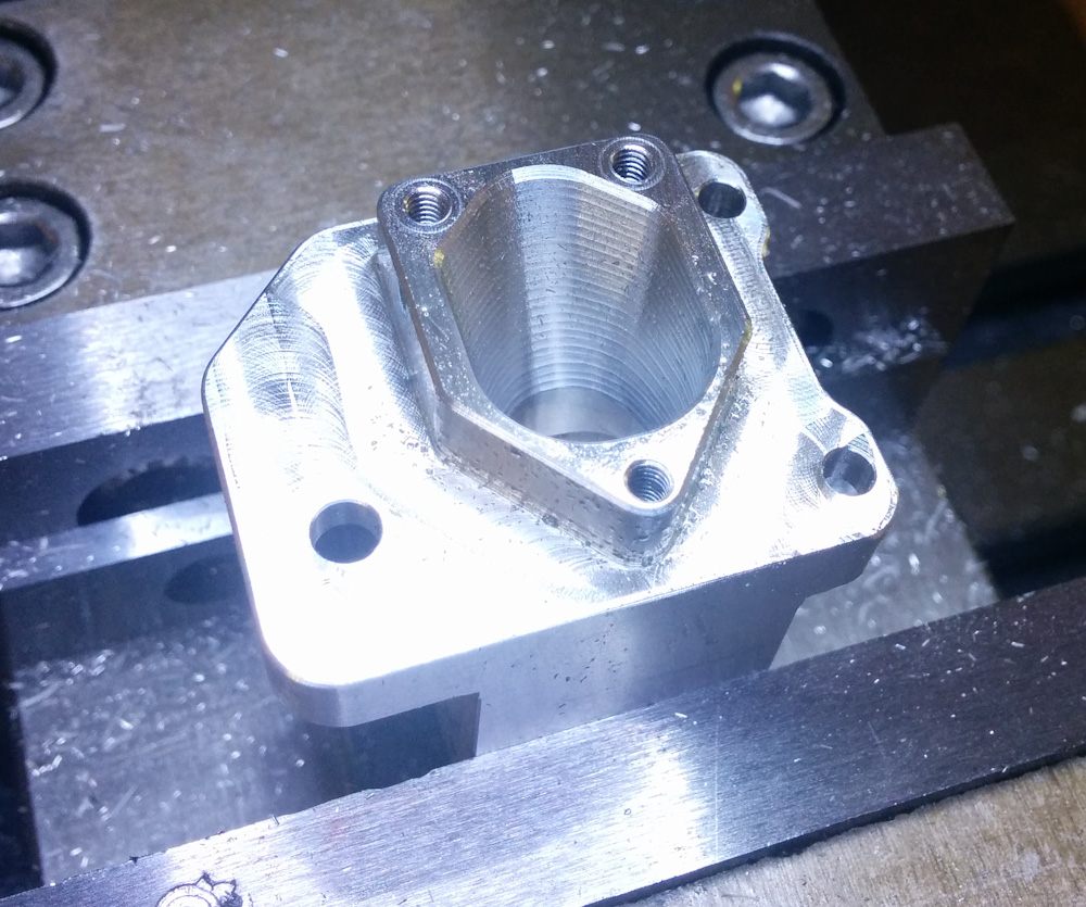
The second version of the valve body, done.
The tricky part was to get the rotor really concentric. I made one and failed to get the hole centered well enough, so the rotor rubbed against the valve body. After some thinking I decided to start with the hole, and then turn the perimeter with the mill-as-a-lathe. Maybe it was luck, or maybe it was that I had an easier time centering the drill bit and reamer, but this time I ended up with a well-centered hole.
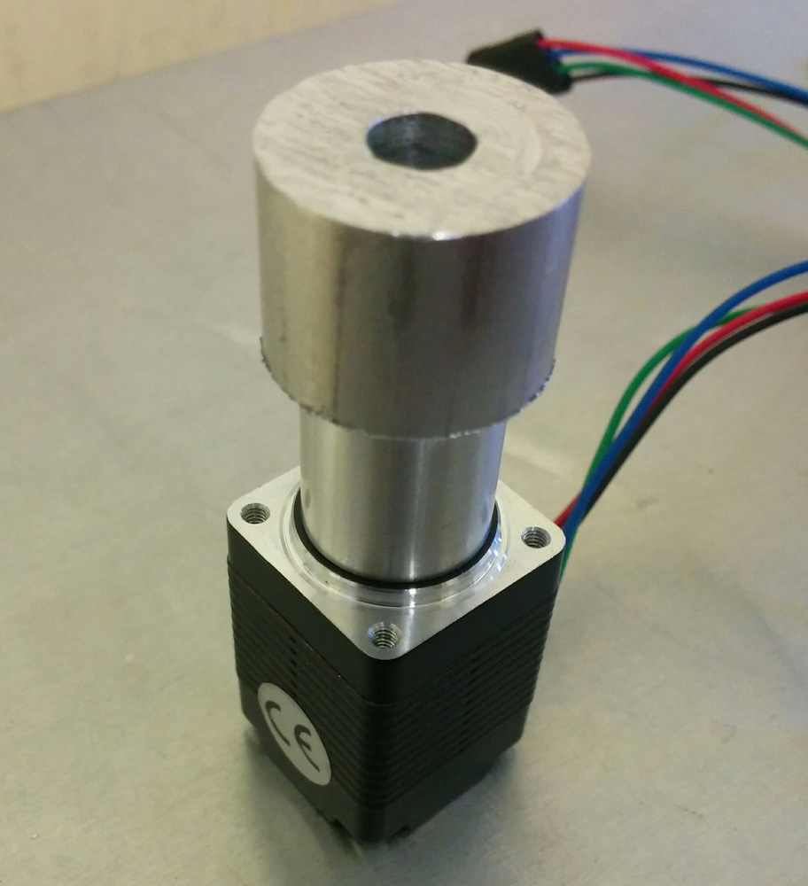
Test-fitting the rotor on the stepper motor. The larger-diameter part will be removed at the end. This time I managed to get the hole for the motor shaft sufficiently concentric with the outer profile of the rotor.
I could now mount the rotor onto the stepper motor shaft and with the motor mounted in the valve body, there was little but sufficient clearance between the rotor and the body.
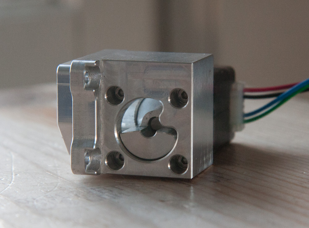
The idle air control valve body with the stepper motor and rotor mounted.
The next step was the point of no return — cutting a hole in the airbox casting. The hole was generated in the same Fusion360 design as the valve body, but I had to measure and model the quite irregular shape of the airbox. There’s a small, flat area in the middle that’s just barely large enough for the valve outlet to come through. I started with air cutting to make sure the end mill wouldn’t hit any of the walls.
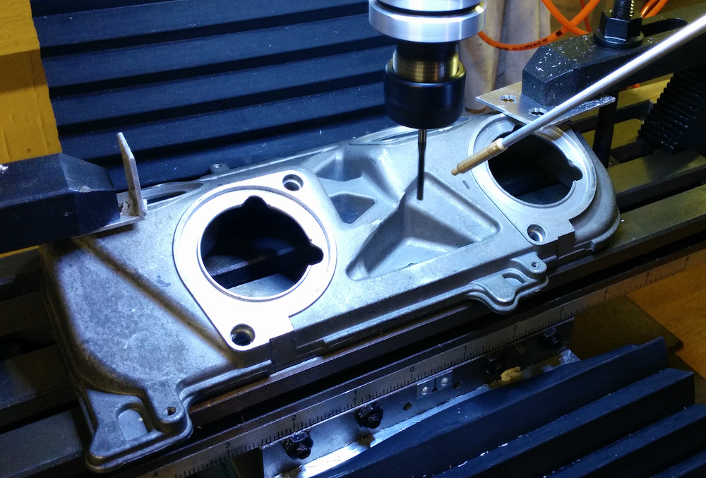
After mounting the airbox casting on the mill table, I ran the program in the air several times to make sure it wouldn’t do anything unexpected.
After ascertaining that the coordinates were at least approximately aligned, I lowered the Z-axis enough that it cut just a tad into the surface.
The final check was to set the milling height so only a thin layer of the surface was removed. This made the extent of the hole very obvious.
Finally, when I was certain the hole was in the right spot. I set the height for the full through cut. This was the point of no return.
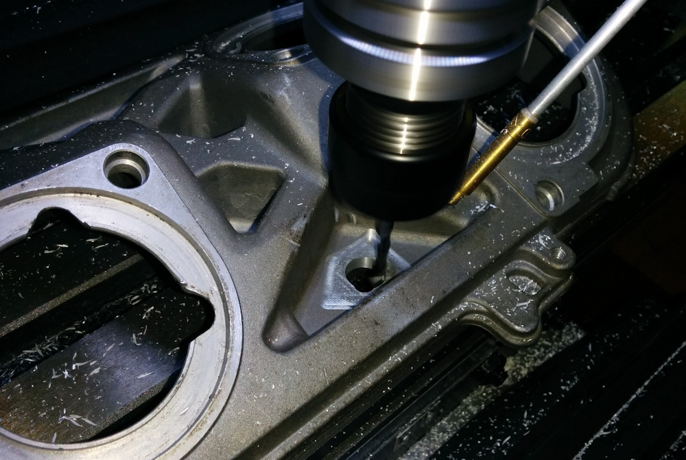
Finally, it was time for the real cut.
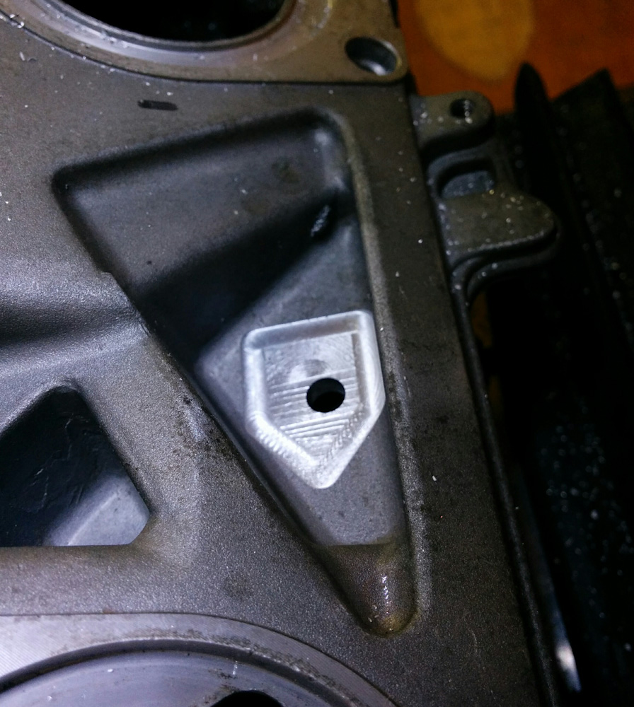
The size of the hole was perfect, which wasn’t surprising since it came directly out of the Fusion360 design. There is about 0.5mm clearance to the part of the valve body that goes through. There wasn’t a lot of margin to the edge of the flat inside surface, though. I don’t think there’ll be a significant air leak there, but it wouldn’t hurt to use a thin gasket.
The hole ended up where it should, although there’s certainly not much margin to the edge of the flat surface in the upper left corner.
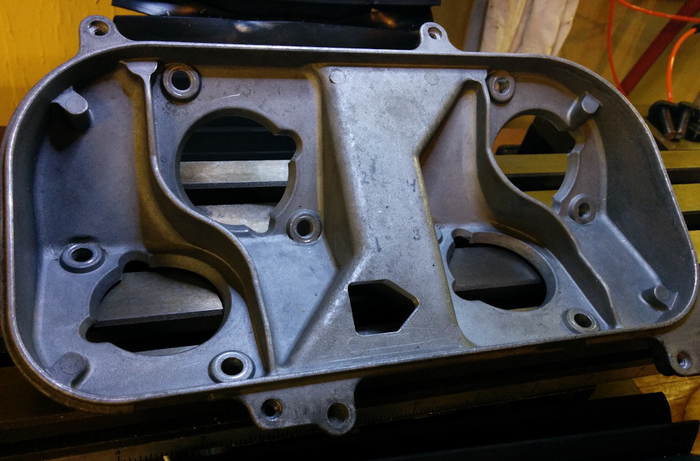
What remains is to drill and thread the three bolt holes in the casting. This is going to be a bit tricky because there’s no obvious way to mount it in the mill with the inside side up, since the bottom is angled. I don’t want to hand drill them, because there’s not much margin for misalignment. I think I’ll figure out some sort of fixture, it should be possible to brace it symmetrically on both sides so the holes can be drilled.
Pingback: Microsquirting the NC30, part #29: Even More Idle Air Controller – Patrik's projects