As I described in the post about making the compressor intake, the gibs took a beating with all the vibration. The gibs on the mini mill, especially the X-axis, leave a lot to wish for in the best of situations. The problem is that the adjustment screws, which are “dog point” set screws (which means they are cylindrical with a flat edge. What that has to do with dogs I’m not sure…) but the gib is at an angle and doesn’t give them a flat surface to push against. This results in the screws pushing “off center” and because they essentially contact the gib at a point, they don’t do a good job of holding the gib in the right position. It appeared there were two local minima in the gib position. There’s the correct one, shown in the picture below, where it bears on the entire slanted part of the way, but it could also end up in a different position where it would move down, the bottom move to the right, and the top to the left. In this position, it only contacted the bottom edge of the way. There was a noticeable notch worn in the gib from this.
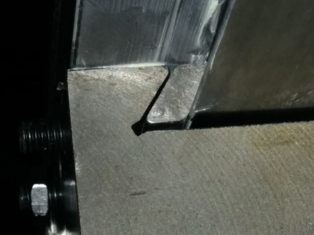
Here’s a close-up of the X-axis gib, in approximately the correct position. However, with a bit of vibration, it would often move down so it contacted the table way only at the point on the bottom.
Looking around the web for ideas for improving the situation, I found a page at “benchtop machine shop” that described the exact problem. He machined proper flats into the gib by plunging a 3/16″ endmill (the M6 dog points are 4mm, 3/16″ 4.8mm) in the right spots. This sounded like a good solution, so I attempted to do the same thing.
Of course, I couldn’t use the mill to do it, and it needs to be done at the correct angle for it to be useful. I attempted to use the entire table itself as a fixture by clamping it to the drill press table, clamping the gib in place, and then putting the endmill in the drill chuck. This did not work well… The drill press has a lot of sideways play in the column, and since the endmill contacts the gib at an angle, it wanted to walk off. And walk off it did. I managed to make some flats, but it was not pretty.
Attempting to hand-make the flats with the drill press did not work well.
Worse than not being pretty, it didn’t work at all. The flats weren’t in the right positions and there were so many overlapping regions of different height that the gib would just wedge itself and lock up. Total failure. Time to order some new gibs. Luckily they’re only like $3.50 a piece.
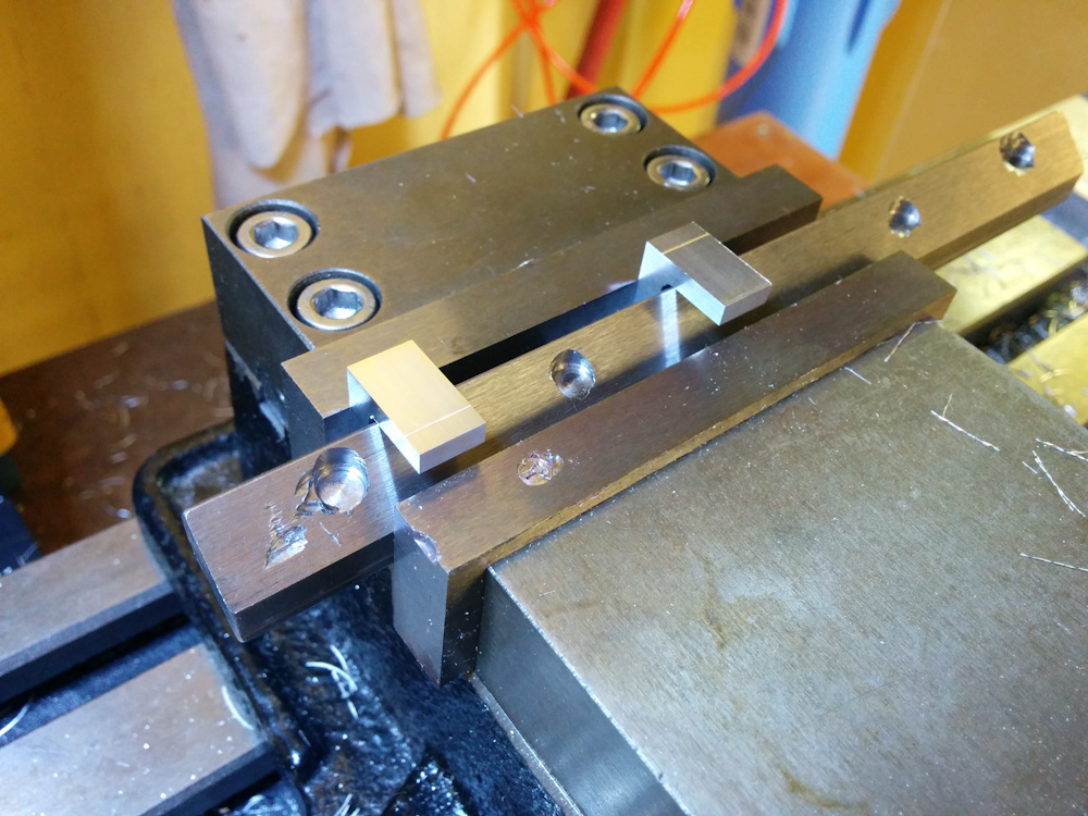
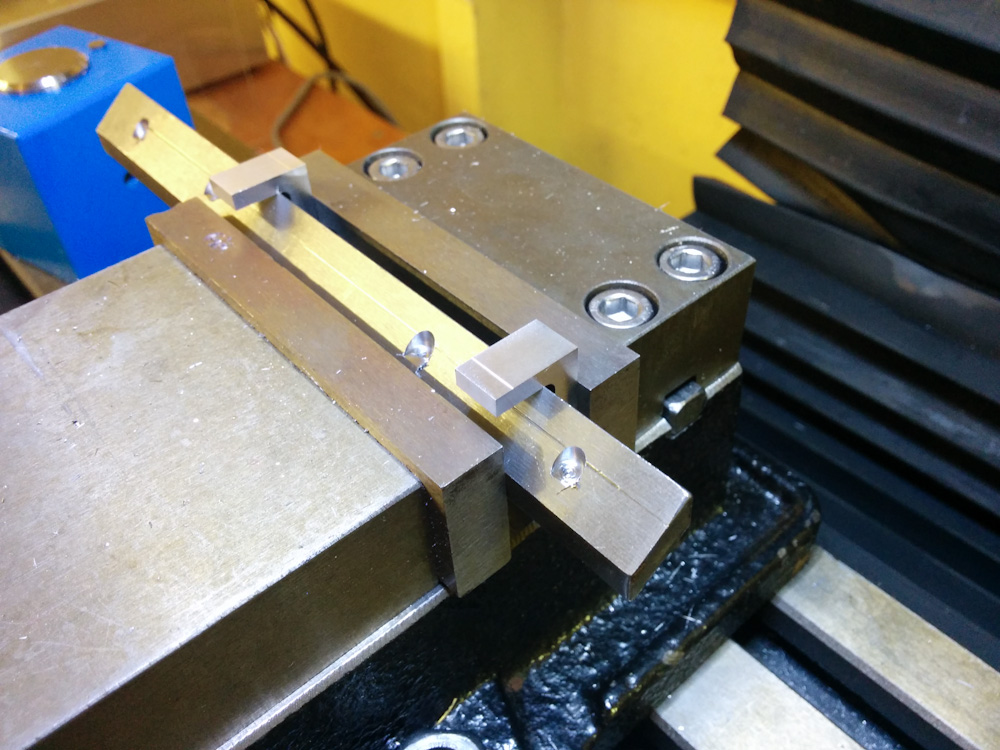
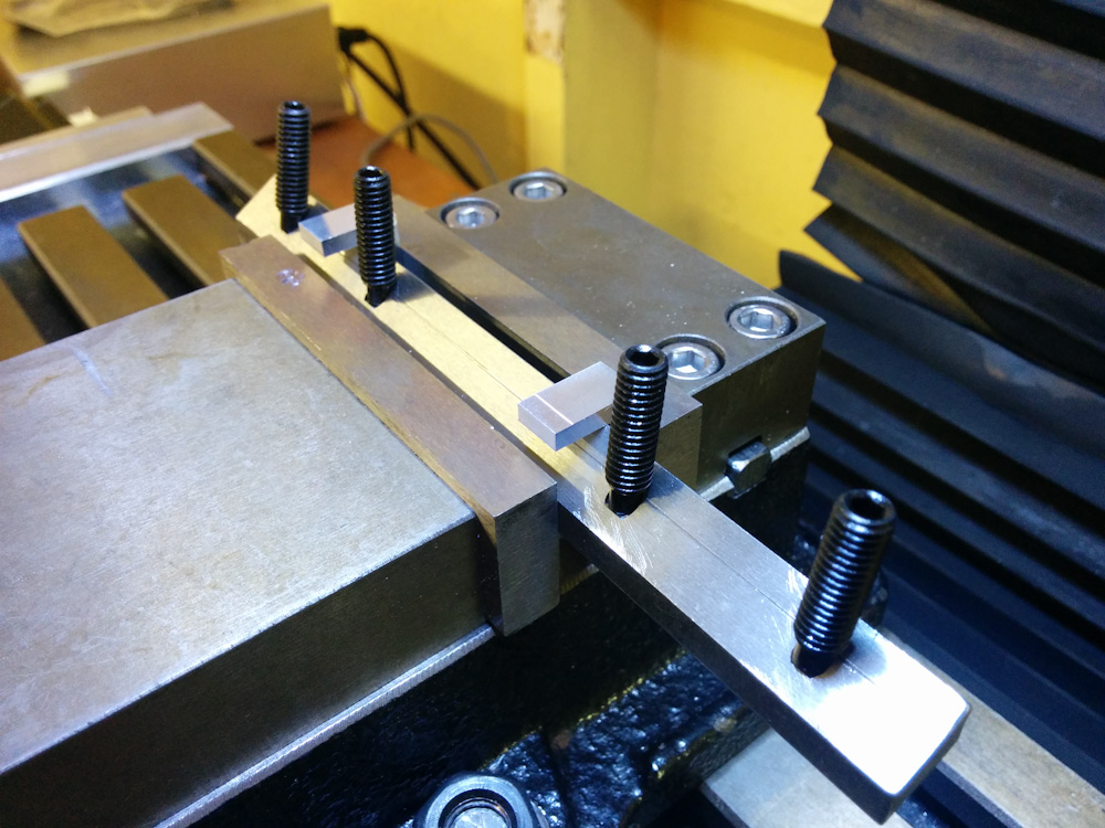
New gibs in hand, I could at least replace the ruined one with one that was no worse than what I started with. Meanwhile, I had designed a fixture in Fusion that would make it possible to clamp the gib in the vise and hold it at the right angle.
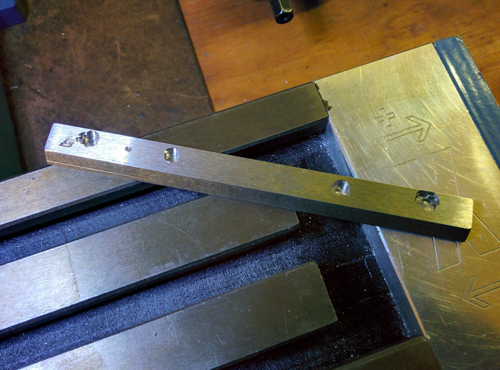
The ruined gib was my test case. Here I’ve completed cleaning up the two flats on the left.
I’ve never attempted machining steel before, so I was a bit apprehensive. However, G-wizard gave me some feeds and speeds and being a bit conservative it worked perfectly. I tried it and with flats that now were just slightly larger than the 4mm dog points (and using new screws that hadn’t been mushroomed from a year of use) the gib was held securely in the right position.
I duplicated the same operation on one of the new gibs. This looks much cleaner.
One of the pristine gibs with freshly cut flats.
The flats on the outer two screws are 4.25mm, just larger than the screws, so they locate the gib. The two inner flats are 4.75mm diameter to give some margin for the flats being a bit off in position.
This seems very promising. I haven’t run it much with the new gib, but I hope now that the screws are in full contact with the gib and the gib in full contact with the way it’ll be possible to keep it quite tight without binding.
If anyone’s interested in doing this on their own mill, here’s a link to the Fusion360 design.
Pingback: CNC mill upgrades: Couplers and gibs – Patrik's projects