Unlike previous posts, there will be no gasoline splashing in this episode. This one is all about CNC goodness.
There is one final part to fitting the throttle bodies that I’ve not touched upon yet. The stock carbs mount to the intakes using short rubber couplers. The throttle bodies have a slightly larger diameter intake than the carbs, so they don’t fit. Something had to be modified.
Initially I had just considered machining down the intake ends of the throttle bodies to fit the rubbers, but that would have left very little material. Instead, I figured I’d go half-way and take out half from the throttle bodies and half from the rubber couplers.
This posed somewhat of a dilemma. I’m used to milling aluminum but I’ve never tried milling rubber. It’s relatively hard rubber, and after reading various people’s reports on the internet, I thought there was a decent chance of it working if I just cooled the rubber down so it got hard. At least it seemed worth a try.
Another problem was how to mount both of the pieces. I figured I could hold the throttle body in the vise by make a set of soft jaws and clamp the airbox end of the throttle bodies in them.
This is very cool, actually. I had already modeled the shape of the throttle bodies quite accurately to make sure everything would fit, and then you basically take a square block and ask Fusion to cut away the shape of the throttle body. What you are left with is a “mold” that should hold the throttle body quite securely.
Once I had the basic shape, I had to tweak it a bit to make sure that it was actually possible to make it in the mill. In some places I had to use quite small ball endmills to cut some contours, and there were some interference problems since you can’t have those small endmills stick out very far. But eventually I worked it out.
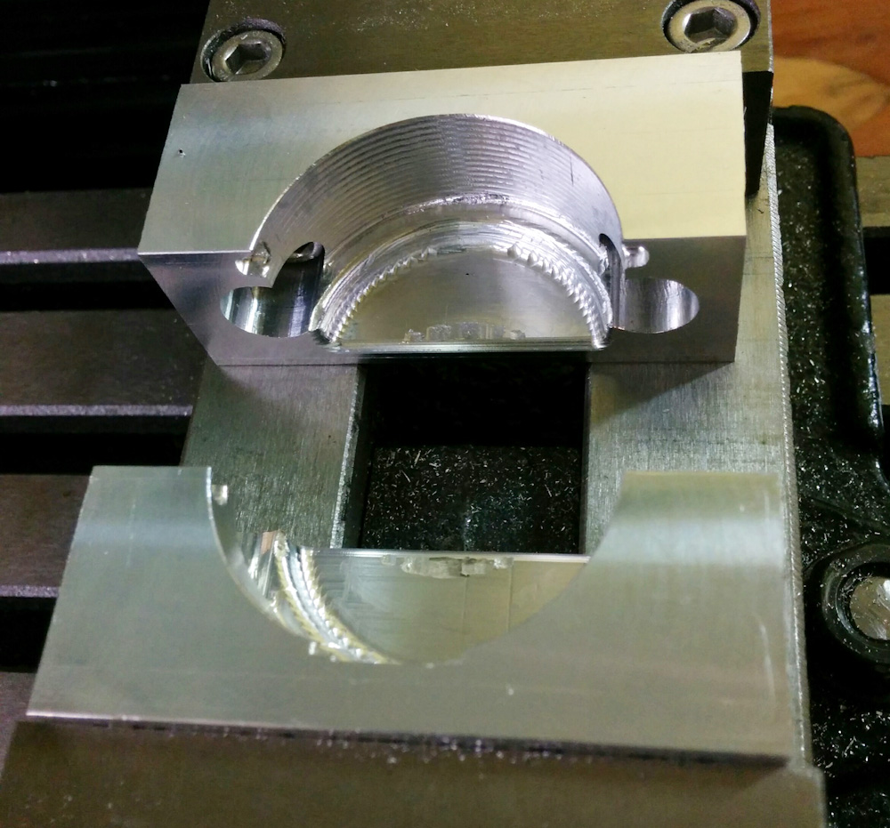
The finished set of soft jaws that will hold the throttle body for machining.
I didn’t really care about the finish, since this was strictly a functional part, you can clearly see the traces of the endmills. But the throttle body fit perfectly and were held very securely.
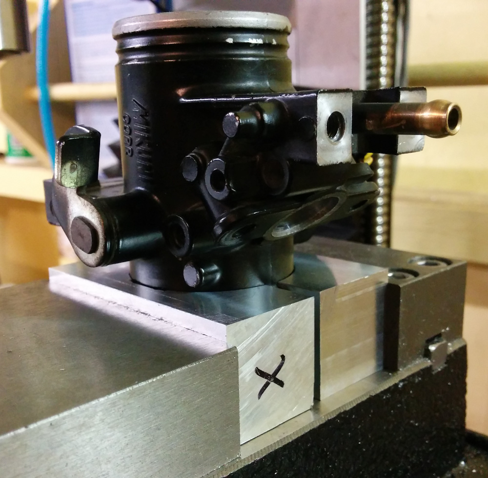
The throttle body mounted in the soft jaws, with the intake end aligned vertically for machining.
The part that needs to be machined down is basically the top end down to where the “wiggles” end.
To mount the intake rubbers, I used the same technique. I had modeled them as accurately as I could measure in Fusion, and then made a “mold” with the body of the intake rubber removed.
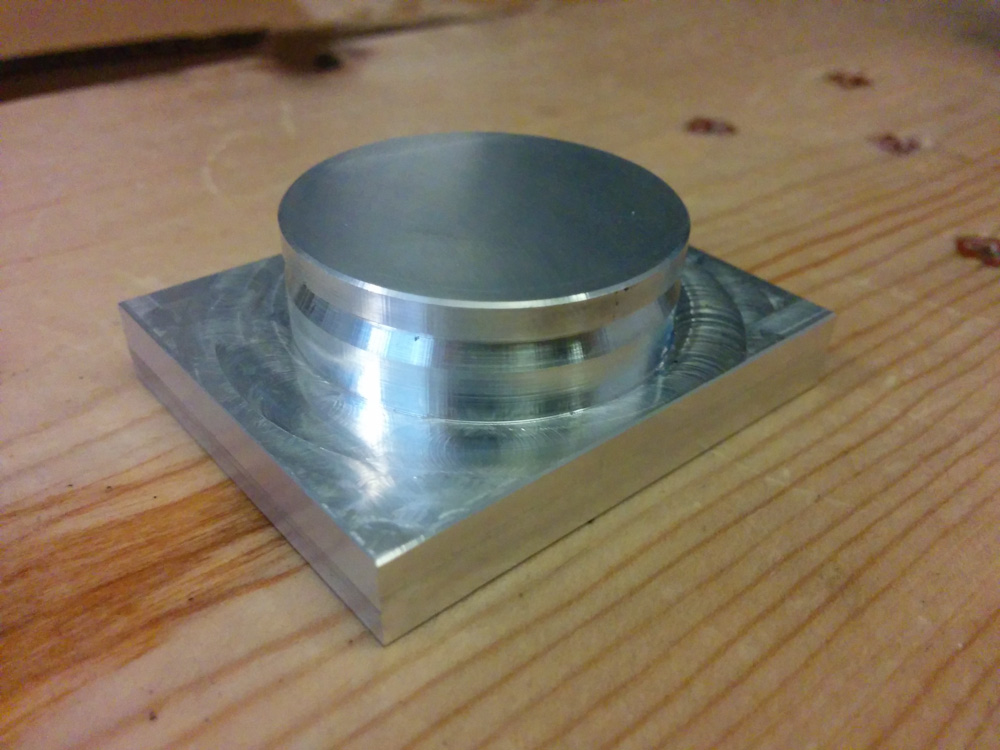
This is the fixture for the intake rubbers, matching the shape of the intake on the engine. The notch prevents the rubbers from sliding off.
The rubbers were also a perfect fit.
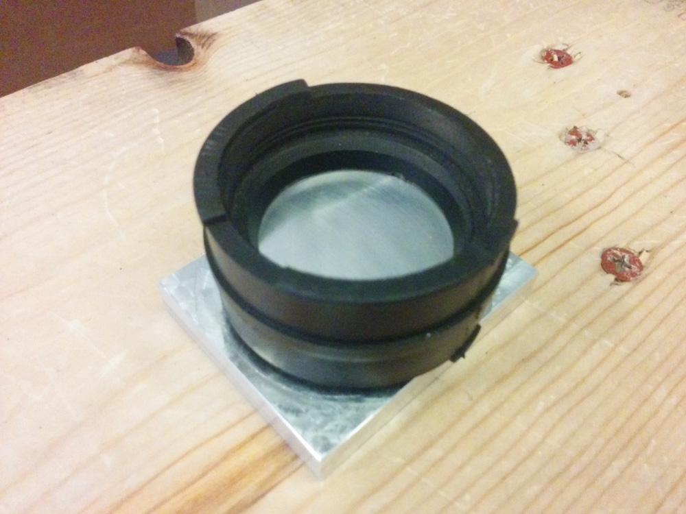
Here’s one of the intake rubbers snapped into the fixture. At this point, it can be clamped with the stock clamps.
I had to decide on what shape to cut the machine the two pieces into. I wanted some notches, like there are in the stock ones that prevent them from moving, but I didn’t really have enough material to make them as large. Instead I just made two small “sawtooth” rings, each half a mm tall. It’s not much, but hopefully it’ll be enough.
The first thing to make sure was that machining the rubber pieces was actually going to work. There’s no point in destroying the throttle bodies unless that will work, so that’s what I started with.
I zeroed the mill position on the fixture with the rubber and a jar of ethanol in the freezer. Once I was all set up, I took the stuff out of the freezer, snapped the rubber into the fixture and clamped it, hooked the chilled ethanol up to the mister, and pressed go. The actual cutting didn’t even take a minute, not counting the tool change since I had to switch to the double-angle chamfer mill to cut the radial grooves.
Since this was a time-sensitive operation, I didn’t pause to take any pictures, but it worked surprisingly well. The rubber cut without a problem and left a very smooth surface. Success!
Proceeding with the throttle bodies, I clamped them into the soft jaws, zeroed the mill on the intake bore, and pressed go. This was also a very short program, and while it’s always nerve-racking to see the mill cut into these pieces, it also worked very well.
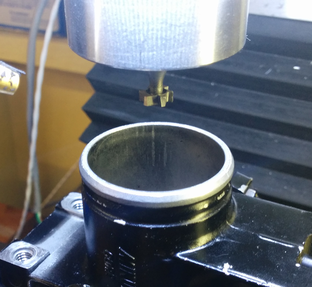
The mill is zeroed on the throttle body bore and we are ready to go. Since I want to leave positive ridges on the part, i can’t cut with a normal endmill, so I used the key seat cutter instead.
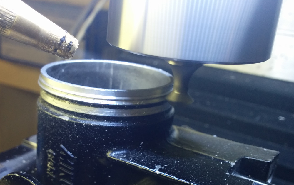
The bore has been machined to size, now the chamfer cutter is making the triangular ridges that will hook into the rubber piece.
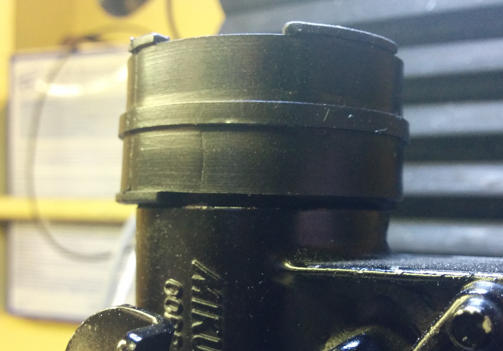
The end result is pretty good. The “grooves” that hold the rubber in place are definitely much smaller than the stock ones, but the rubber piece snaps fairly securely into place.
The intake rubber in place on the throttle body.
So that’s one thing less to worry about. We are now at the point that it should be possible to physically mount the entire throttle body assembly and the airbox onto the bike!
So what’s left? I need to add the harnessing for the injectors and the throttle position sensor, which shouldn’t take long. There are two large, unsolved problems remaining:
- First, making a replacement for the fuel tap that also has a fuel return line, and routing the fuel hoses so the fuel pump can prime properly.
- Second, figuring out how to connect the throttle linkage between the four throttle bodies. They are meant to be lined up in a line right next to each other, but now the two cylinders are much further apart, and some sort of linkage needs to go between the front and rear cylinder pair.
I believe I’m seeing the end of the tunnel!
Patrik,
Have you looked at the QuadraMAP product that Don MacPhail makes? I’m using it in my GSF400 and I’m planning to upgrade my EX250 with it also.
Greg
No, I read the article about the “synchromap” at http://www.synchromap.com/ but I didn’t know there was someone selling it. I was considering building my own, although it looks like that’s pretty much what I was planning to make. The only thing I was going to do different was to feed in the 5V sensor reference so the final output would be relative to a known level and not be affected by shifts in the voltage regulator on that board.
What’s the size of the board? It would be nice to be able to stick the MAP sensors between the cylinder banks.
here’s the website page for the QuadraMAP, it has a description of the circuit’s functionality but no pictures (Don seems to be an old-school sort of guy, which I like):
http://efi.ttrignition.com/quadramap.html
The size of the QuadraMAP was surprisingly small. I remember that when I held it in my hand I was surprised at how small it was. It comes to you as a small black plastic case with four tiny hose ports (non-barbed) and a little wiring pig-tail sticking out of one side. Don’t know the exact measurements but definitely no more than a 2 inch square, and about an 1 inch high. He sells it for $125 + shipping, which I thought was reasonable considering it has 4 MAP sensors inside.
It also has a phase discrimination feature (working off of one of the MAP sensors) that simulates a cam sensor if you want/need that for your project. Whenever that particular sensor goes below 80kPa it sends out a logic/square wave 12 volt signal.
Don lists the QuadraMAP as being very robust with regard to heat so I mounted it just a short distance below and behind the throttlebody rack. You could definitely fit it in between the V of your cylinder banks.
Pingback: Microsquirting the NC30, part #30: Finishing up the airbox work – Patrik's projects