If there hasn’t been that much activity lately, it’s because I’ve been pondering how to solve the fuel pump mounting problem. The pump is just large enough that when you include the diametrically opposite inlet and outlet, there just isn’t enough room, and since the pump can’t self-prime with any amount of air in the inlet, there are
Eventually I decided mounting it the way Greg’s GSX400 fuel pump works that he mentioned in a comment to a previous post is the way to go. His pump is mounted in a little “surge tank”, which has the advantage that you don’t need to connect the thick inlet hose directly to the pump. It also makes it easier to ensure the pump doesn’t suck air, since it will draw from the bottom of a large volume where the air will be on top. It also makes it possible to mount a fuel strainer, which I was going to attempt to do in the tank but have largely given up on.
The most important thing to verify was that the pump could actually self-prime when stuck with the inlet directly into a container of gasoline. Since the pump has a small inlet coupler, that will still contain air in this situation, and indeed the pump proved unable to purge that air.
With my patience near an end I conjectured that it would work if I could get the air out of the inlet, and the way to do that is to make a hole the air can get out through… So I carefully drilled a 2mm hole in the inlet, right next to the pump. If any swarf got into the pump it would be bye-bye with that one, so I was very careful to first plug up the entrance to the pump interior, drill the hole, and then make sure the inlet was aimed downward until I was sure there was no loose chips there.
With this “improvement”, it worked — the pump now happily primed and pumped out the air contained in the pump and then ran happily. (Which was damn lucky, since the hole I just drilled precludes ever mounting a hose there again…)
It was then “just” a matter of drawing up and manufacturing this “pump housing”. There is enough room for it to go in the battery compartment, along with the Ballistic Lithium battery, but only barely. I had to redesign it several times to make it fulfil all the requirements:
- Inlet into the housing must be ~65mm high from the bottom to let the hose from the tank cross into the battery compartment.
- Total width can not be more than 80mm.
- The pump outlet and power connector must be more than 60mm up from the bottom on the rear side of the housing.
- The fuel strainer must somehow be attached to the inlet.
- And importantly, all of this plumbing has to allow for as much air as possible to get out of the box and flow back up to the tank.
The tricky part is that the width requirement implies that the AN-6 inlet port and the fuel strainer must sit one above the other. The height requirement on the inlet means it needs to be on top and the strainer on the bottom. But that means the inlet into the box, which is the strainer, actually is close to the bottom and that will prevent the air in the box from venting.
Eventually I came up with what I believe is the solution: The strainer is near the bottom of the tank, but I’ll make another, small, hole into the inlet near the top of the box. The sole purpose of this hole is to get air out when it is initially filled with fuel, so it doesn’t have to be big. It just so happens that the fuel injector service kit I got (see Microsquirting the NC30, part #20: Leaks…) came with an extra filter, a very tiny strainer with a 6mm OD. This way it won’t be possible for dirt in the fuel to flow into the pump housing through this hole, and the majority of the fuel should go through the main passage through the strainer anyway.
With that idea it all sort of came together, but it’s still going to be kind of a chore to manufacture. The pump is suspended with 2 O-rings diagonally in the box, held by the lid and a lower bracket. The lid also has an O-ring that seals the lid to the box. Here’s a Fusion360 rendering of what it’s going to look like:
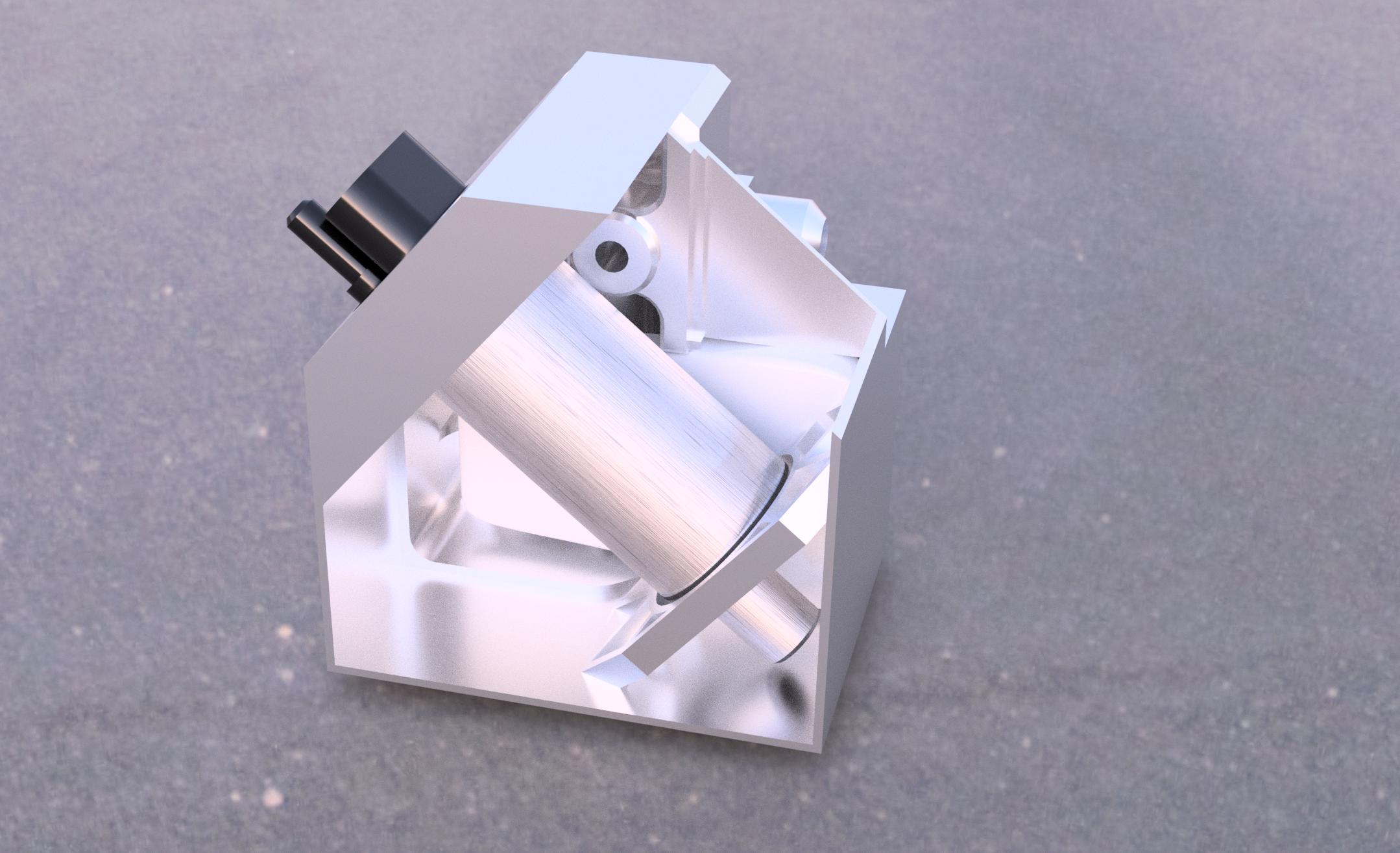
Here’s a rendering of the fuel pump housing, with two sides removed to show the inside. The AN-6 inlet is on the back side facing right, the bag-like thing behind the fuel pump is the fuel strainer bag. The hole above the fuel pump is the air vent hole where the fuel injector filter will go. The lid is in the upper left.
The whole thing consists of 12 parts, 11 of which will need to be welded together (plus the lid). Four of the pieces are 3-dimensional and will be milled, the remaining 8 are the walls which are made of 1/16″ (1.6mm) 6061 Aluminum.
So far, I’ve made the most complicated part, the inlet/strainer attachment:
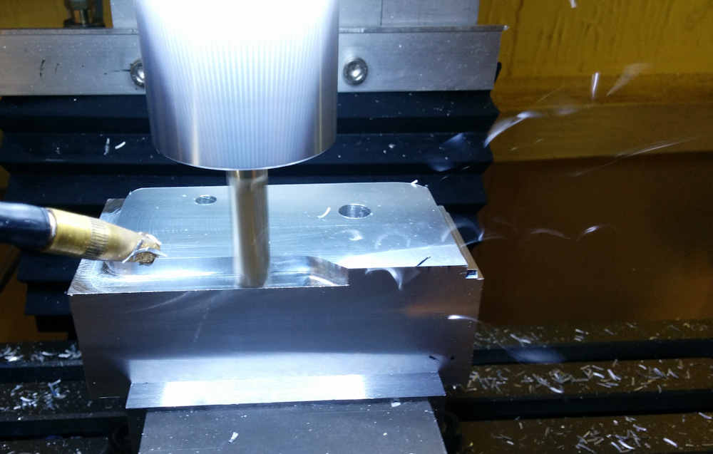
Because of the three-dimensional shape of this piece, it started as a big chunk of metal. I think this is the smallest fraction of final/initial metal in any piece I’ve made.
Check out those chips flying in the picture, by the way. This 1/4″ 3-flute endmill, at 2000mm/min, eats through material at a surprising rate for a “Mini Mill”.
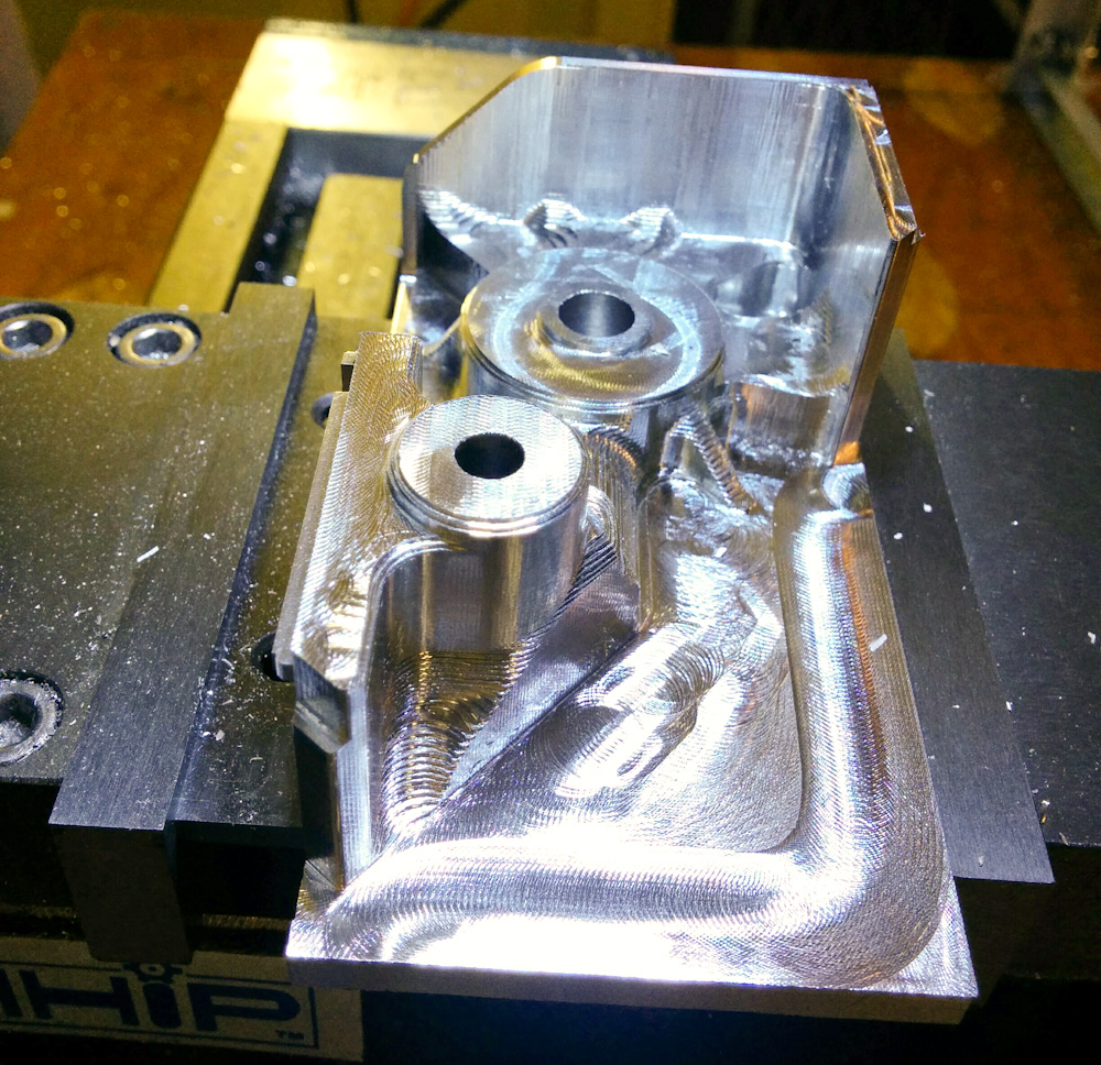
Here, most of the material has been removed, but progress was halted because of a broken endmill. I had forgotten to adjust the speed cutting the pocket where the strainer attaches in the top of the picture.
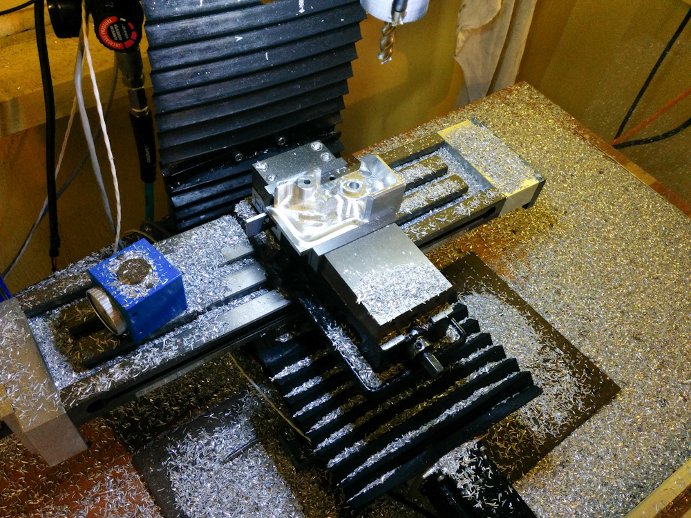
You can kind of see why this is called “subtractive manufacturing”. That’s a lot of chips…
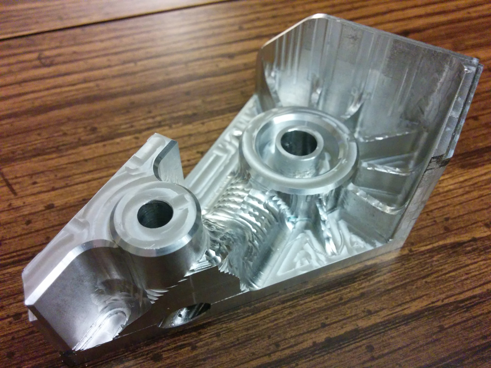
Here’s the final product. Cosmetically, it’s far from perfect, but since nothing will be visible I don’t really care about appearance. Both the fuel strainer and the inlet port fit, so we should be good to go.
I’m working on the remaining parts, so those will show up in the next post.
Now it’s getting really interesting, this thing is going to be truly unique.
Pingback: Microsquirting the NC30, part #25: Fuel pump housing progress – Patrik's projects
Pingback: Microsquirting the NC30, part #31: Finishing up the fuel pump housing – Patrik's projects