As I mentioned in the last post, I’ve been working on quieting down the new 60-gallon air compressor. People claim a significant fraction of the noise from an air compressor comes from the air intake. For this reason, I was going to fit a larger intake filter/silencer.
The stock air filter is a chunk of what looks like fiberglass sandwhiched between two layers of metal mesh. Hence, to be able to attach something to the intake, I had to manufacture an adapter.
After careful measuring on the compressor, I designed a piece in Fusion that would slide into the slot that holds the existing fiberglass filter and convert to a 1.25″ pipe. The larger air filter has a 1.25″ pipe thread, so then I could run a short length of pipe and locate the filter on the wall behind the compressor.
The air filter is quite large, so this adapter piece ended up being the largest design I’ve ever tried to make on the mini mill, and because it’s hollow you end up needing long endmills to reach into the hole. Long endmills are much more prone to flexure and vibration than the ones I normally use, and the long leverage also means that any play in the head of the mill gets amplified.
I ended up using 3/8″ flat and ball endmills with about 70mm of stickout from the collet. This piece was really pushing the limits of what you can do with the mini mill, and even then total machining time was probably upwards of 4 hours.
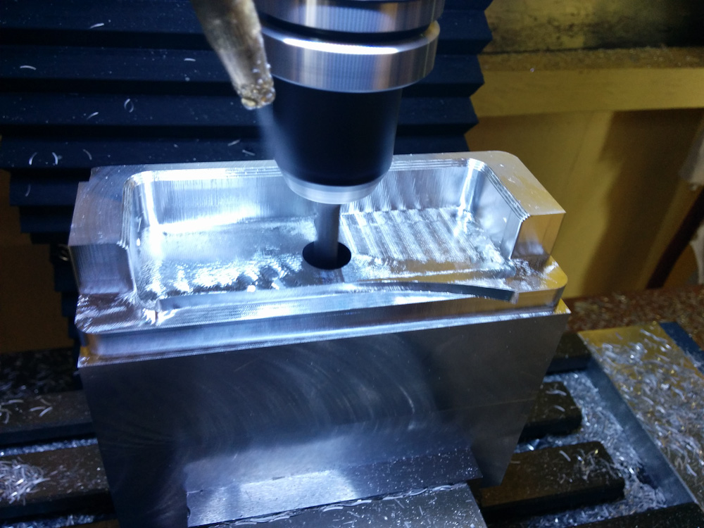
This is a short bit into the machining of the inside of the compressor intake adapter. This is still using the normal, short endmill.
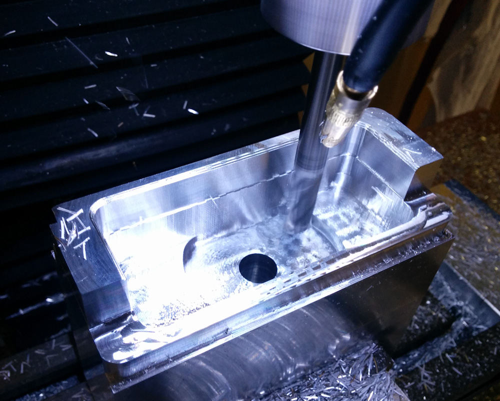
This is the 72mm long 3/8″ endmill that I used to get into the hole and clear out the material.
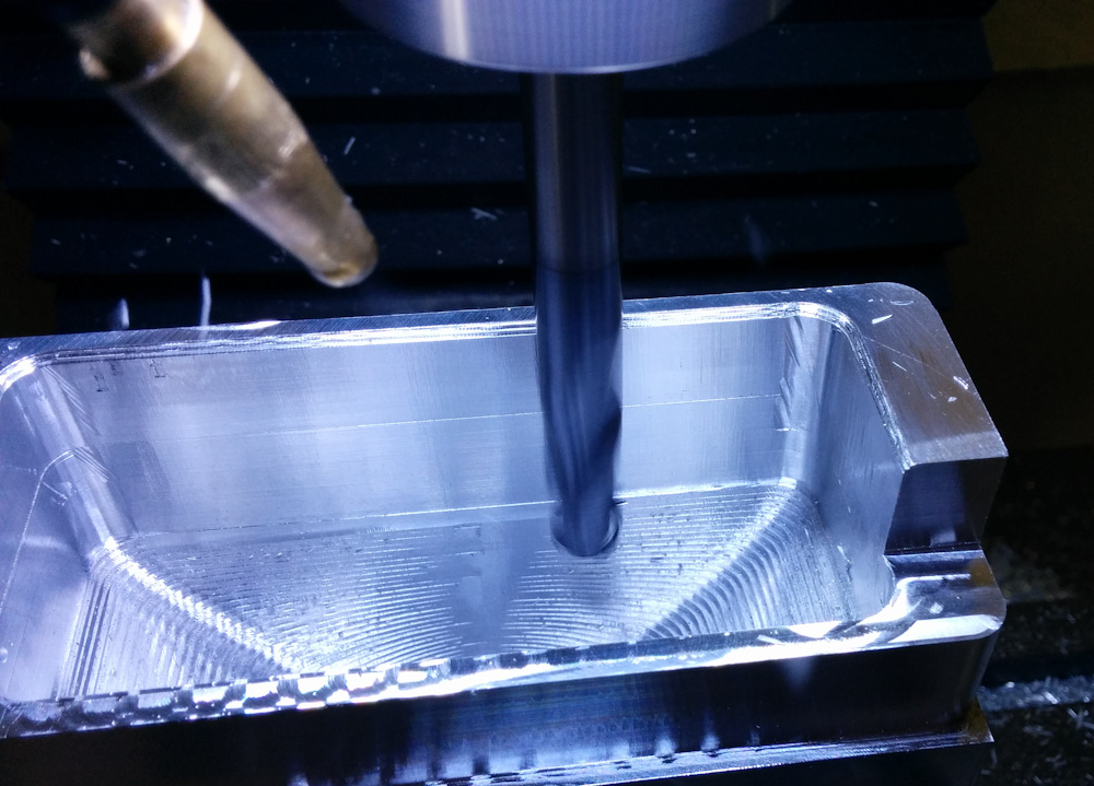
The final operation of the inside was to clean up the contours with the ball nose endmill.
To give you an idea about how much the mill struggled with this job, I collected some clips of the various operations into a movie:
There were basically two problems. The first was that the long endmill would chatter. This is when the periodic disturbance of the flutes hitting the material causes the endmill to start vibrating like a tuning fork. This is the very loud and high-pitched squeal you can hear in the video above. Because this is a resonance phenomenon, it’s worse at some RPM than others. I kept lowering the RPM until I got to 900 (normally I use 2500) where it finally was somewhat tolerable.
The other problem was that the flutes cutting into the material causes a vibration in the mill table itself. Any play in the gibs or backlash in the ball screws means that the table can shake back and forth every time the flutes take a cut. This is the much more lower-pitched vibration that you notice at some points in the movie.
The latter problem can be mitigated by taking a deep enough cut that the endmill always has a flute engaged. In this situation there is a more constant cutting force that tends to not excite vibrations. That’s the reason I take those very deep cuts (14mm) in the movie. 14mm was way better even than 3-4mm.
Anyway, it was painful both for me and the mill, but we made it. The gibs really needed adjustment afterwards and some of the adjustment screws were mushroomed from the vibrations in the table. Pretty bad…
After a few small adjustments, the piece ended up fitting perfectly.
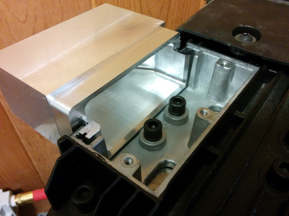
Test fitting the intake adapter on the compressor. (I did that before machining the outside so I had some options in case it didn’t fit.) Luckily, it did.
Next step was to make a lid that could be welded to the adapter and screw into the three holes where the stock lid mounted. This job was a bit more reasonable, since it was just a flat piece. I cut some fins into it for cooling. The two were test fitted and then welded together.
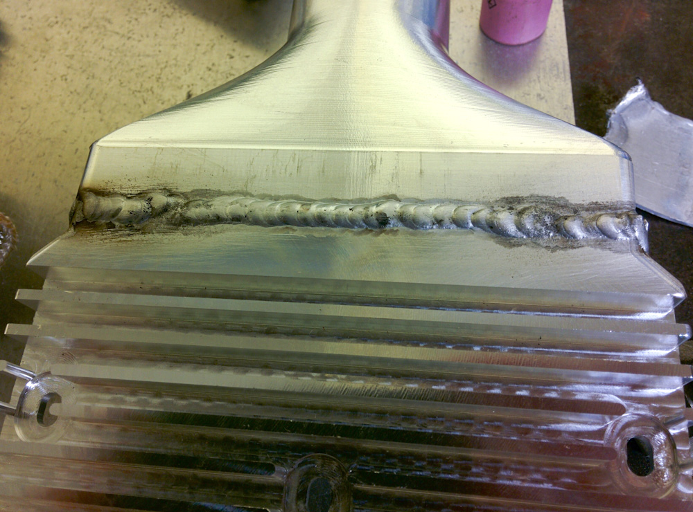
The welds really do not look good, but it’s not like this is critical work.
With the adapter completed, I could finally mount the new intake filter. I used a flexible rubber coupling to connect the intake to a 1.25″ PVC pipe going to the filter. Since this is all covered by the “muffler box”, I placed the filter in the corner. This is the furthest away from any openings on the box, and is also the suction side of the fan blowing air over the compressor, so it should give it nice and cool air to suck in.
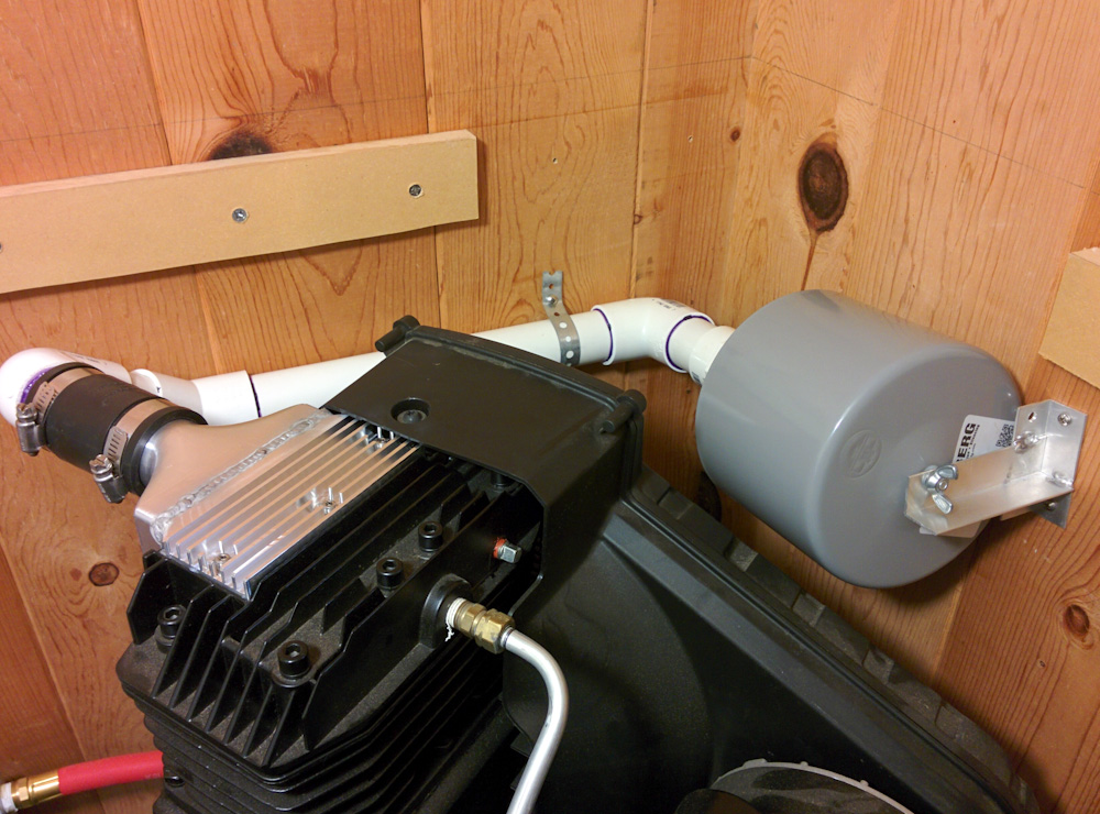
Here’s the final arrangement of the intake filter. It’s quite large, so it was placed in the corner. A piece of rubber flex coupling connects the PVC pipe to the intake.
The rubber coupling is a source of some concern, as the compressor head gets very hot (easily over 100C) during heavy use. Time will tell if it holds up, but for moderate air use the compressor just doesn’t run enough for it to get very hot. The real test will be trying to use an HVLP pain gun or maybe my air-driven sander.
The final piece of the puzzle was to apply a layer of fiberglass insulation on the closet walls around the compressor and on the inside of the box.
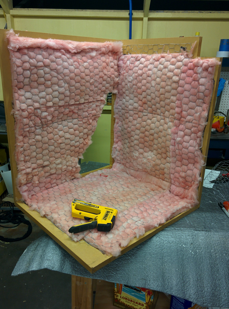
To absorb the sound coming from the compressor before it can get out of the box, I mounted fiberglass on the inside. It’s held in place with chicken wire stapled to the MDF box.
I also added 1/2″ rubber vibration isolators under the compressor feet to cut down on the vibration conducted into the concrete floor.
So, how does this all work? Actually, remarkably well. The larger filter itself made a noticeable difference, and the box took it from annoyingly loud to perfectly tolerable. I haven’t made any measurements, but I can now stand outside of the closet and without a problem have a conversation with the compressor running. Outside of the garage, it’s basically inaudible. It’s not even in the same ballpark in loudness as the old one.
I made a movie comparing the stock intake, the new filter, and the final configuration with the fiberglass insulation. The auto gain on the microphone makes it difficult to appreciate the volume differences but you can kind of get an impression by comparing it to how my voice sounds.
That completes the saga of quieting down the air compressor. I sure hope the neighbors appreciate the amount of work I’ve done here, but I must say that it’s also awesome to be able to use the mill without needing ear plugs like I did with the old compressor.
I like the run the really loud stuff for four hours so that I can make it less loud. Hope the neighbors appreciated the extra pain for long term gain…
Eeeexactly!
Pingback: CNC Mini Mill #13: Gib mod – Patrik's projects