Ever since I bought the NC30, I’ve been unable to get the joints where the front cylinder header pipes attach to the collectors under the bike to not leak. The joints are clamp joints with a cylindrical fiber gasket, but I could never get the gaskets to fit inside the clamps.
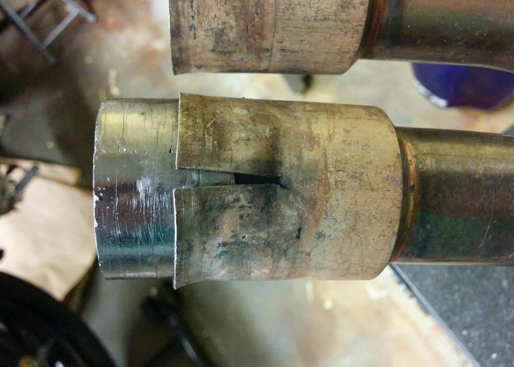
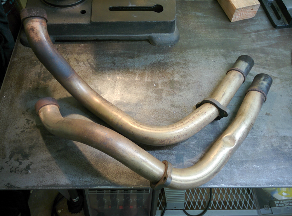
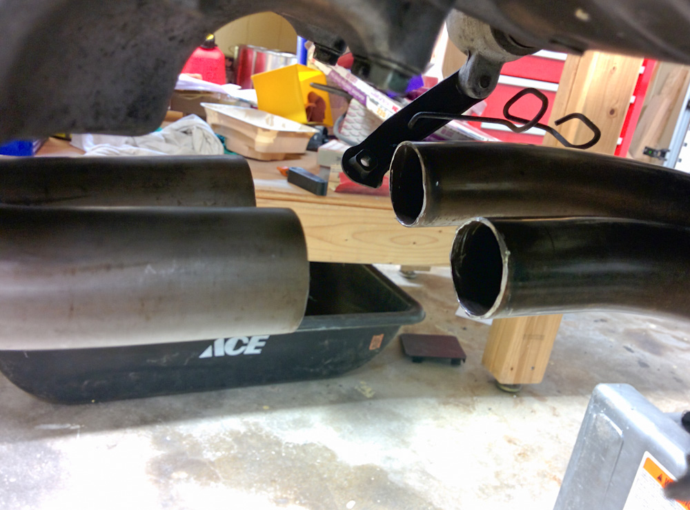
These are the old exhaust pipe joints, with the gaskets that don’t fit. It turns out this is not a stock exhaust.
After asking on the 400greybike forum, it became clear that this is not a stock exhaust, so I guess then it makes sense that the gaskets don’t fit. The header pipes, though, appear to be stock.
Normally a little exhaust leak doesn’t matter much. However, with an oxygen sensor any amount of air getting into the exhaust gas will make the lambda readings incorrect, so it was imperative this be fixed somehow so the lambda readings would be reliable. (Even if the average pressure in the exhaust pipe is higher than ambient, so on average it would be exhaust gas leaking out, the exhaust comes in pulses and in between them the pressure can actually become less than ambient, so some air would get sucked in.)
I decided to get rid of the clamp-type coupling completely and instead use a double-slip coupling. As its name implies, a slip coupling is where two pipes just slide into each other. A “double” slip means there are three pipes, where one side slides in between two that are welded together on the other side. Because the fit is quite tight the thermal expansion as the inner pipe heats up more than the outer one will “clamp” the join together when it’s hot.
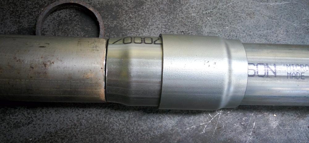
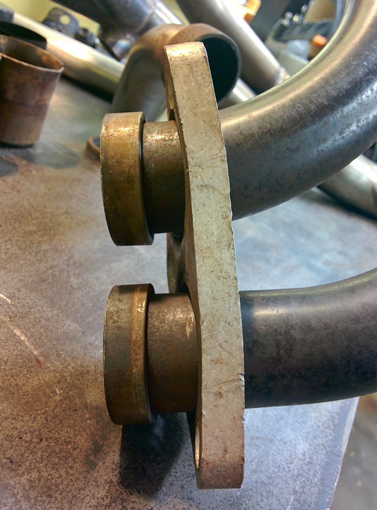
One of the double-slip couplings. The part on the left is slightly expanded and slides in between the pipe on the right and the outer collar, which gets welded to the pipe.
As you can see from the picture above, it’s a very clean design. The precisely expanded slip joint sections, made out of 403 stainless, were ordered from Burns Stainless, which sell parts for fabricating exhausts. The exhaust pipes are very close to a 1.375″ or 35mm, which luckily is a standard (albeit quite small, as far as exhausts go) size.
To make it easier to work on the bike, I decided to make a small square out of mild steel angle iron that would fit on my Harbor Freight bike lift and make it possible to stick the front wheel of the bike on the lift and jack it up. It’s been a while since I welded mild steel, but, wow, it’s so much easier than aluminum or even stainless.
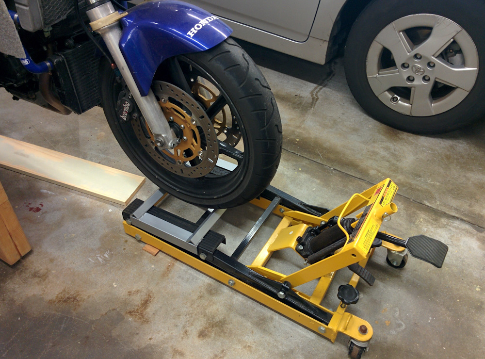
The silver-painted custom holder makes it possible to jack up the front wheel of the bike with the bike lift.
To get the rear wheel up higher, I put the car ramps under the rear wheel stand.
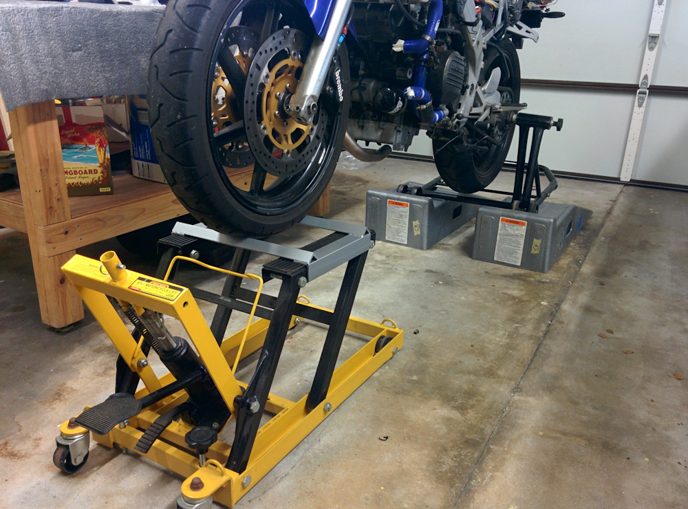
With the front wheel jacked up by the bike lift and the rear wheel elevated by putting the stand on the car ramps, it’s much easier to access the exhaust system.
It looks precarious in the picture, but it’s actually quite stable. For added safety, I also ran a lift strap around the triple tree and a roof beam in the garage, so the bike can’t really fall over. It’s now much easier to work on the exhaust under the bike.
The first step was to get rid of the existing couplings, but while I had the pipes off, I tried polishing them up with some Scotch Brite pads, too.
The front cylinder headers need to have their rear ends, where the clamp gaskets would go, cut off.
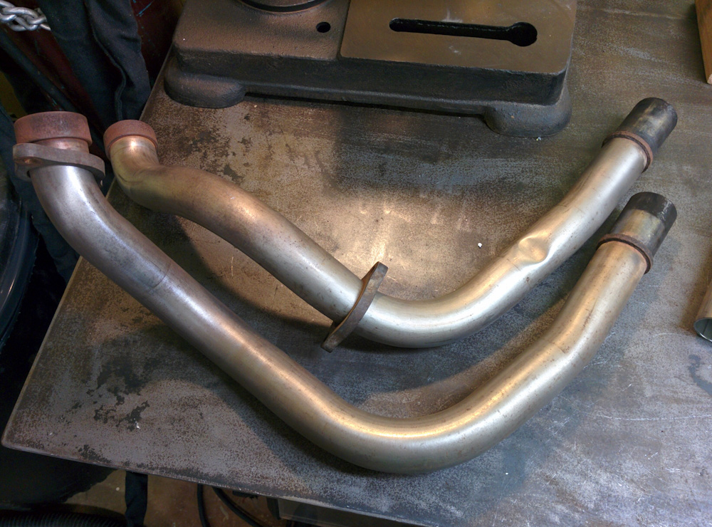
The Scotch Brite pads cleaned up the surface corrosion quite nicely. Note that the collars that hold the pipes to the exhaust ports are very rusty. These are apparently normally made of mild steel, not stainless, so I’m tempted to cut them off and replace them with stainless while I’m at it.
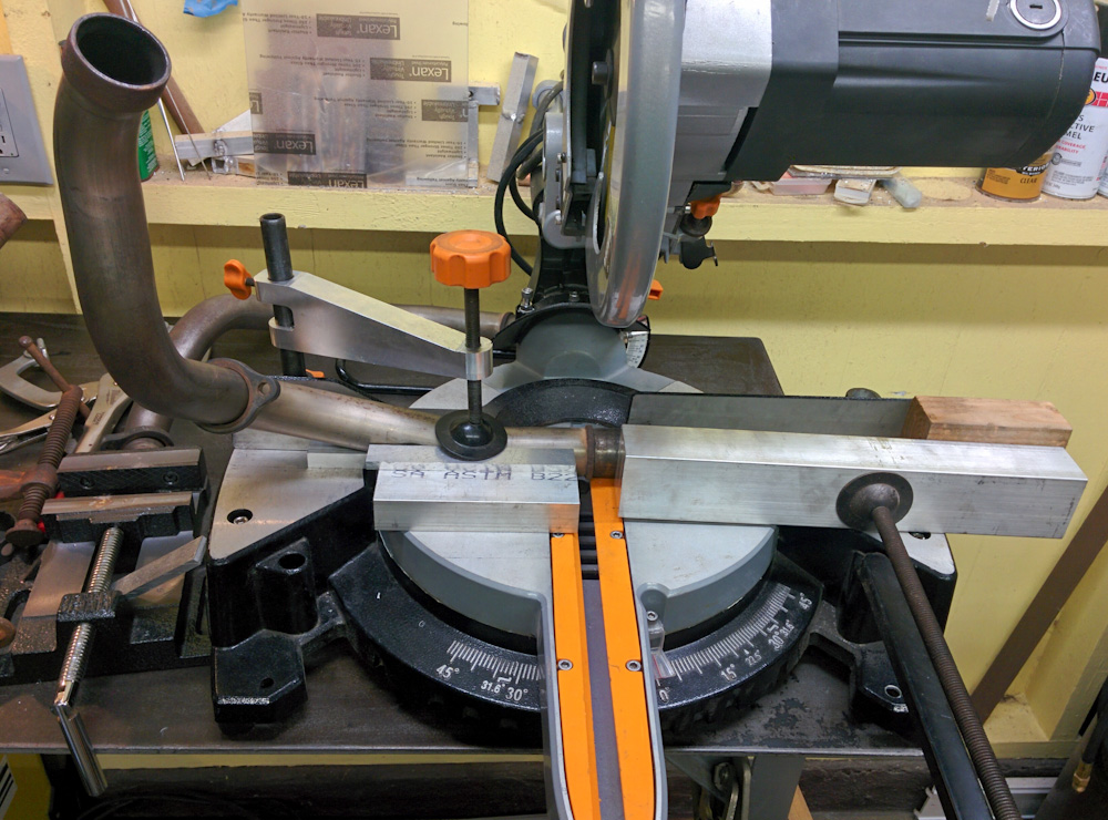
The first pipe has been clamped in the saw. Because of the numerous bends, it was a bit tricky to get it securely mounted.
The header pipes could be mounted in the saw and be cut cleanly. The collector ends, though, could not, so they had to be cut with the Dremel cut-off wheel. Those ends will definitely need cleaning up before anything can be welded to them.
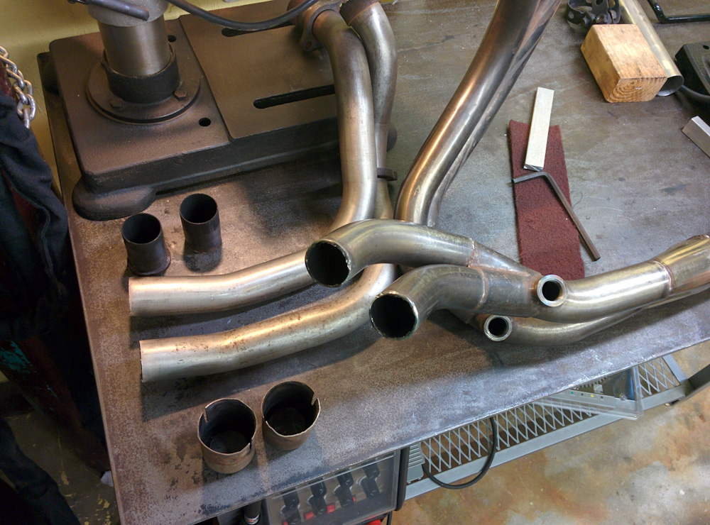
There’s no going back now — all coupling parts have been cut off.
After cutting off the couplings, I put the exhaust pipes back on the bike to see whether they were aligned.
Here’s the hole that now needs to get joined. Unfortunately, the pipes don’t quite line up. It looks pretty good from this angle, but seen from below there’s a noticeable offset.
Of course, they were not. I’m not sure whether this is because something has been bent out of shape or if it’s because the aftermarket collector was never meant to join up with the stock headers, but this needs to be adjusted somehow. A prime candidate for being out of alignment is the attachment to the rear header pipes, which is bent out of shape.
This is the plate that bolts to the ends of the rear headers. It’s bent, presumably from overtightening the nuts, and binds on the collars on the pipes.
Because it’s bent inward where it’s supposed to seat on the collars for the exhaust pipes, it binds on them. From the dark soot marks, you could tell that there had been a small exhaust leak here, too, so it’s possible it’s not seated quite right here. Maybe this is why the bottom is not quite aligned?
I’d like to replace or at least straighten this plate, but getting it off requires cutting the collars off the pipes. I don’t think it would be a big deal welding new ones on, but I don’t have any proper material to make them from. I have 1.5″ pipe that will just fit over the headers, but they’re only .065″ thick and the existing ones are about twice that. It appears that what I would need is 40mm OD, 35mm ID, which probably is possible to get in Europe. Maybe I can get my Dad to mail me a piece… After all, I only need a few cm of it.
If it comes down to it, I might have to cut the header pipes and introduce a little kink in them to improve the alignment. I’d prefer not to, but the slip joint has to be aligned.
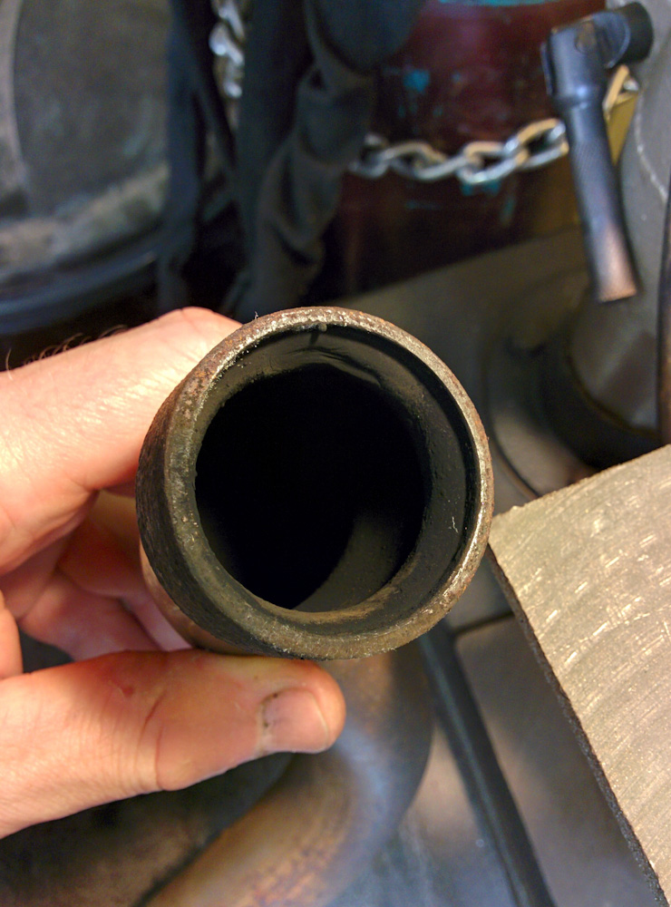
The inside of the headers are completely covered in soot, in case we needed yet another example of how rich the bike has run before.
Finally, just in case we needed another example of how rich the bike has run up to this point, the inside of the headers are completely covered in soot, as are the exhaust ports in the head. I’d really like to be able to look into the cylinders to see how they look, there’s so much carbon everywhere. I wonder if getting the bike to run at lambda 1.0 or even a tap leaner during cruise operation will cause this to gradually burn off, once there’s some excess oxygen in the hot exhaust gases.
You mention that the NC30 has 35mm outer diameter pipes.
Guys on VFRDiscussion indicate the stock VFR800 pipes are 36mm outer diameter. If the material is 1.5mm thick that would result in a 33mm inner diameter. And that doesn’t take into account any narrowing due to welded joints. Makes you wonder what goes into the engineering decision making on the choice of exhaust pipe size, doesn’t it?
Like everything else with engines there’s probably a trade-off/balancing act between forces going on here. On one VFRDiscussion thread the guy who runs (or just acts as the spokesperson for) the British company that makes Motad (exhausts) commented that they didn’t use larger-than-stock tubing in their replacement stainless steel VFR800 exhaust system because doing so causes the average gas velocity in the system to drop too much.
When I get back home I’m gonna measure the exhaust pipes on everything in the garage: The EX250 (125cc cylinders), the GSF400 (100cc cylinders) and the VFR800 (195cc cylinders) to see if there’s any correlation/conclusion to be seen.
The Burns Stainless web page has some links to exhaust system studies, and I found http://www.burnsstainless.com/EPG_PART_IV.pdf particularly interesting. It’s by the CAFE foundation and reports the effects of various aircraft exhaust system designs by measuring the exhaust pressure as a function of time. This means you can see all the various pulses and reflections that happen and makes it clear just how complicated an exhaust system really is.
As for the diameter size, I think the trade off is basically between back pressure and exhaust gas velocity. Less back pressure is good, but higher gas velocity is also good because that helps draw the final exhaust gas out of the cylinder. Where the optimum is can’t be easy to figure out except experimentally on a given engine and exhaust type.
Pingback: Microsquirting the NC30, part #34: Finishing up the exhaust – Patrik's projects