I was feeling pretty good about how things were going when I “just” had hooking up the tachometer left. That’s when I ran into an unsolved problem. From looking at the tachometer signal with the oscilloscope, I had determined that it consisted of short, square pulses, 4 per engine revolution. The Microsquirt outputs a tachometer signal, but it outputs one pulse per cylinder per engine cycle, i.e. per 2 revolutions. There is no way to configure it to output a higher frequency.
Another problem was that the signal to the tach was 7V, not 12V. And more strangely, if I unplugged the tach itself, the signal stopped even though the engine was still running. I realized this meant the stock ignition box must sink an output from the tach. Sure enough, the tach input showed 7V when unplugged.
This meant I could at least test it. While the “normal” Microsquirt tach output is a +12V pulsed signal, you can reroute the signal to one of the open-drain outputs. After doing this, the tach did indeed respond but, as suspected, it showed only half the RPM. Luckily the fact that the Microsquirt tach output is a 50/50 high/low square wave did not seem to affect how the tach responded to it.
I toyed with the option of building a pulse-doubling circuit, but realized that I have an unused pin in the connector to the wideband controller/comm box. The Atmega microcontroller that sends the oxygen sensor data to the CAN-bus can easily generate a pulse train with arbitrary frequency using the built-in timers. And it is also possible to request the RPM (or any other piece of data, in fact) over the CAN-bus. This sounds like a perfect solution.
There’s one small problem, though. The Arduino pins can’t handle 7V, and they can’t be switched between low and high-impedance using the timer, so an external MOSFET would be necessary. This was a bit annoying, since it meant the circuit board had to come out of the box…
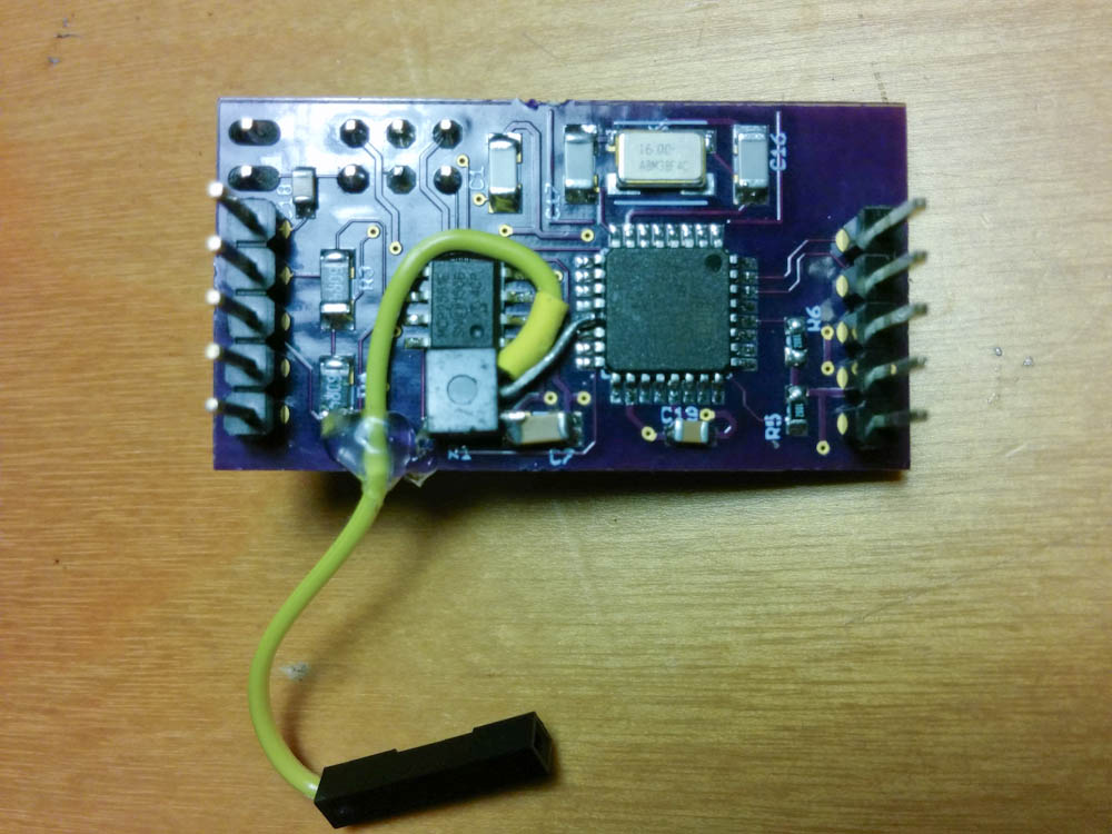
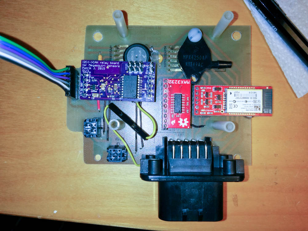
The formerly professionally-looking circuit board is starting to slum it. I soldered a small MOSFET I had in on hand to ground and the timer output pin, and added a short lead to the drain pin.
The packaging will have to be done again, but it wasn’t that big of a deal. I connected a MOSFET to the timer output pin and ground on the circuit board with the Atmega and brought the drain pin out to a lead. When the Arduino pin is high, it’ll sink the tach voltage, when the pin is low, it’ll be disconnected. Piece of cake.
The other end of the lead connects to the unused pin on the Ampseal connector. Not too bad, this is what happens when you work with prototypes…
With the hardware worked out, I had to improve the software on the Atmega a bit. The Megasquirt CAN-bus protocol description at http://www.msextra.com/manuals/ details the different messages and how to send a request to the Microsquirt to respond with the RPM. Amazingly, it worked (almost) right away!
With the RPM in hand, it was not a big deal to set up Timer1 on the Atmega such that it toggles the output pin every time it reaches the set limit, and calculate what that limit should be for a given RPM. I had some glitches in the tach response until I realized that I should only change the timer limit from the interrupt that fires when the timer hits the limit. This prevents a scenario where, if you are setting a lower timer limit, the timer may already have ticked past the new limit and must then overflow the 16-bit register and wrap around before it hits the limit again.
I also noticed that the tach is noticeably nonlinear. It starts out showing about 500RPM less than the input frequency just above idle but by the time you get to 10,000RPM, it’s showing almost 1000RPM too much. That’s not a big deal, I fit a second order polynomial correction to “correct” the output frequency. I also discovered that the tach has noticeable hysteresis; the displayed RPM for, say, 7000RPM is quite different depending on whether you approach it from below or above. I guess this means that there’s some friction in the mechanism. It’s only maybe 400RPM, though. Not a huge deal.
So that’s where we’re at now. I’m pretty happy with the progress over the weekend. I still have to package the circuit board and the wideband controllers back into the enclosure and run the tach wire, but then I think it might finally be time to put it back together (at least the important parts like the gas tank) and go for a ride to see what happens with the engine under load.
Patrik,
Your project is great so far. It’s obvious to me that you’re several steps above my level with regard to engineering and electronics. That combined with the fact you’re working on a very similar project to mine (’93 Suzuki GSF400) makes me very interested in every choice you make along the way.
Have you decided on injectors yet? I’m looking forward to seeing what you choose and reading your reasoning/analysis/opinion of that choice.
I chose the Secondary Injector Rail off a ‘09-’11 Kawasaki Ninja ZX-6R (the set that is airbox-mounted). I used both the injectors and the aluminum airbox mounting bracket and fuel rail, which perfectly matched the spacing of my Suzuki’s bank of Mikuni BST32SS carbs. I had the injectors tested by a fuel injection specialist here in Spokane (held open at a constant pressure of 43.5psi) and they flowed ~165 to 170cc/min. Based on this flow rate I did the math for 80% injector duty cycle and it came out good for a 100cc cylinder at 14,000rpm.
Greg
I’m purposefully leaving the fuel setup until last, because it seems like the most difficult part and I want to get warmed up before getting there. I looked around for suitable throttle bodies, and the 90-degree V4 geometry means there’s little chance of finding something that will fit as-is. I found a set of throttle bodies from a 1982 GPz 1100 on ebay that seems promising. They have basically the same bore diameter as the stock NC30 carbs and cleanly separate into 4 parts, so I should be able to build a bracket that mounts them onto the stock carb rubbers. The injectors are standard EV-type Bosch injectors, so I got a set out of an Opel Corsa or something similar that has about the same power. I don’t remember the flow rate offhand now but it should give me something like 60% duty cycle at full power, which hopefully will be ok. The biggest challenge will be mounting the throttle bodies to the airbox, which will require some custom-made adapters since the carbs are hard-mounted to the aluminum airbox bottom.
But like I said, I’m putting that off… 😉
Pingback: Microsquirting the NC30, part #27: Idle Air Controller – Patrik's projects