Way back in June, I talked about making the parts for the fuel pump housing. Since then, I’ve slowly been gathering courage to weld it together. My first practice runs welding together 1.6mm (1/16″) 6061 sheets were not encouraging. It’s just very easy to blow out one of the sides if you add a bit too much heat.
One thing that Jody on the WeldingTipsAndTricks Youtube channel (highly recommended if you’re learning to weld) recommended was to use a piece of copper on the back side of the weld. This acts as a heat sink and makes it a lot more forgiving. I tried it and it works like a charm.
So I started slowly working on it.
Figuring out the order of assembly was a bit tricky. I started by welding the bottom to the large piece that has the fuel inlet. Then added the small front plate. For welding the thin pieces to the large CNC milled parts, I added an inside flange on the large parts. This make the mismatch in thickness less and makes it easier to weld.
As usual, it didn’t always go so well. Here’s the aftermath of accidentally touching the filler rod to the tungsten electrode. All that crap needs to get cleaned up, otherwise you get a contaminated weld.
That’s as far as I’d gotten back in August. At that point, the work on the fuel tap and idle air control took precedence for a while until I got back to it this week.
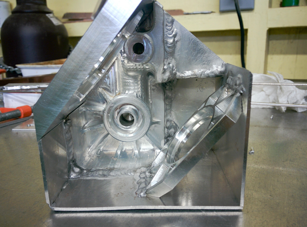
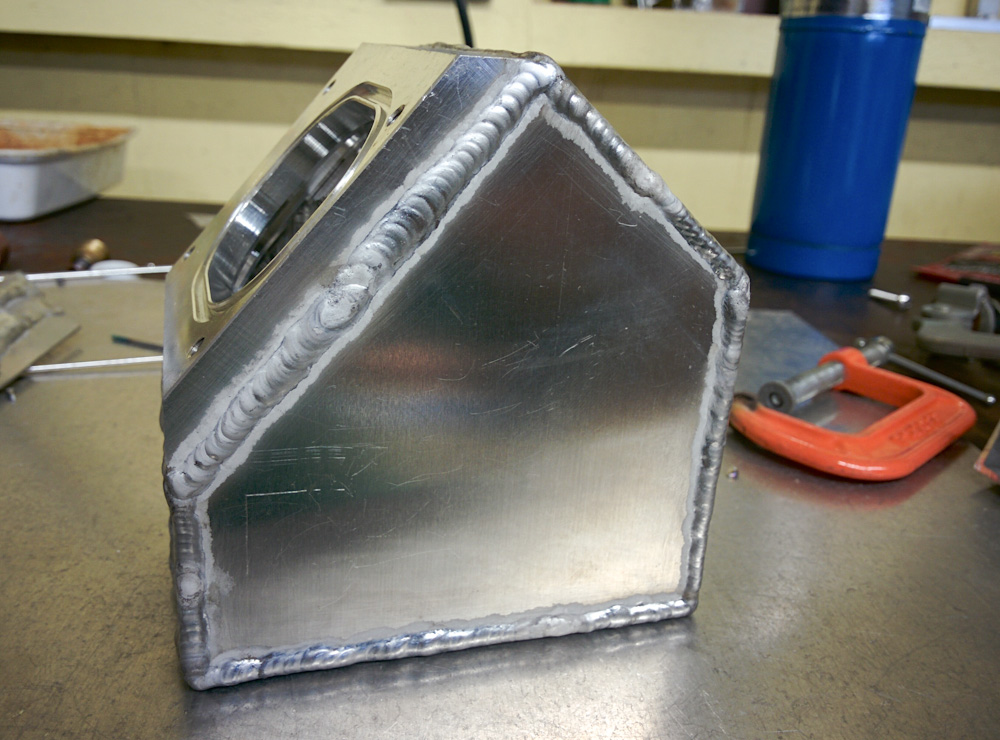
Here the bracket that holds the lower end of the pump has been welded, and the lid tacked in place.
These are the only welds in the assembly that are between two thick pieces, so these were done with a lot higher current and a thicker tungsten electrode.
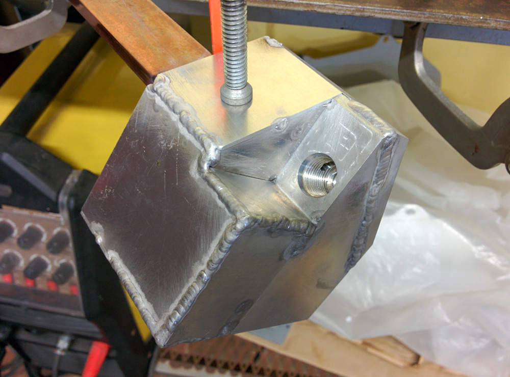
After adding the top of the box here, the only part remaining is the one open side. Note the copper bar used as a heat sink.
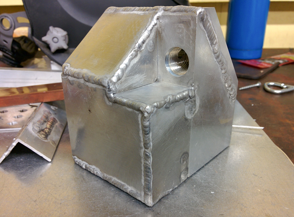
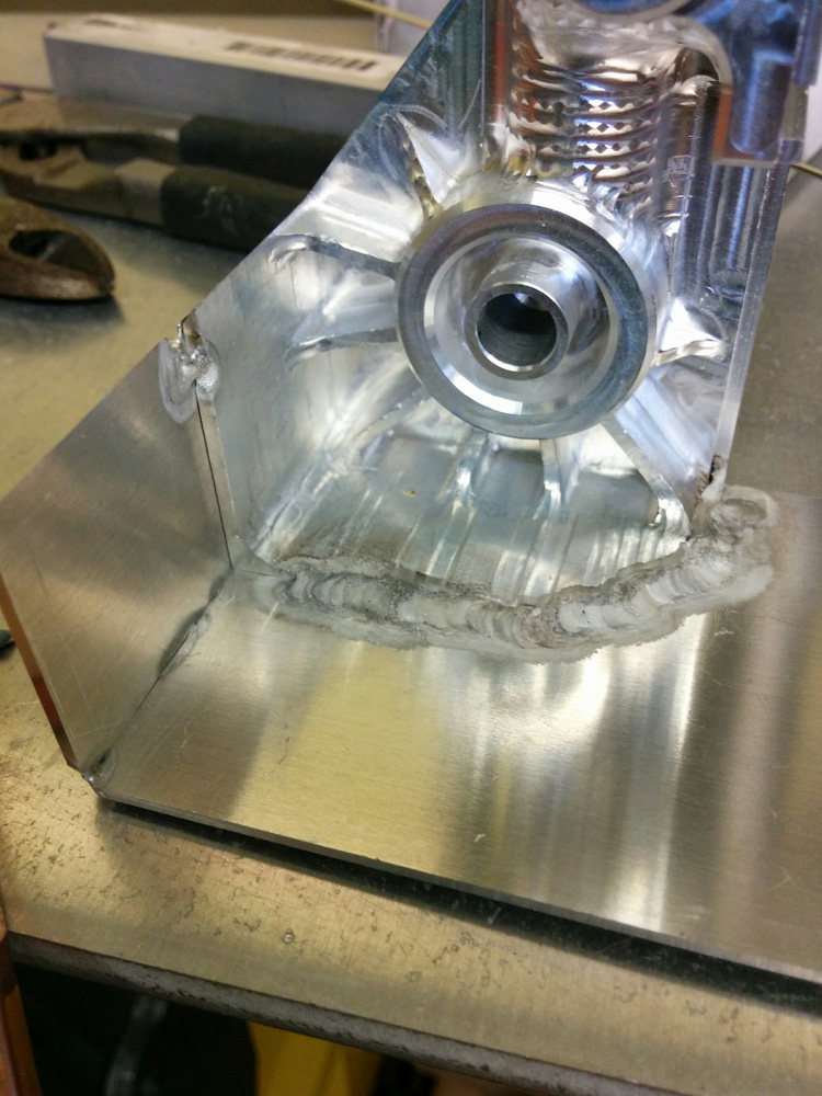
This is what the completed front side, with the fuel inlet, looked like. The outside corner welds don’t look terrible. Being able to have a short tungsten electrode, and the copper backing bar, really helps.
Note that the three welds that make up the inside corner are on the inside. I deliberately planned this, since welding outside corners is a lot easier than inside ones. However, this was a bad idea, as you’ll see further down.
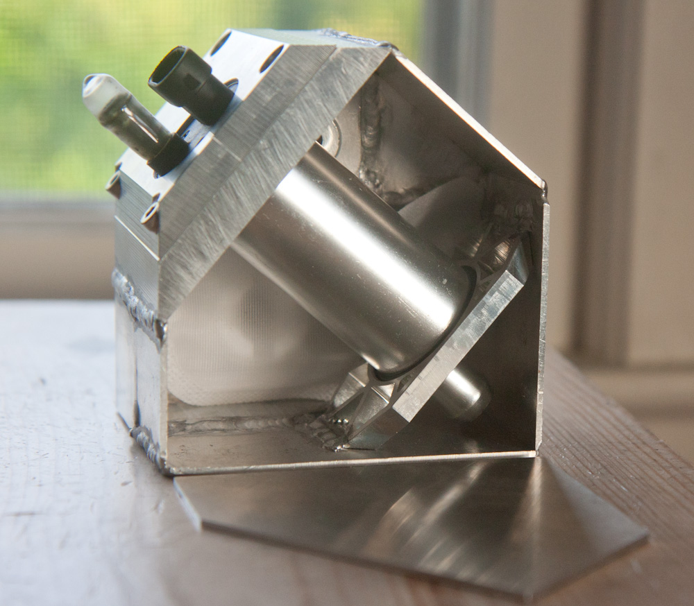
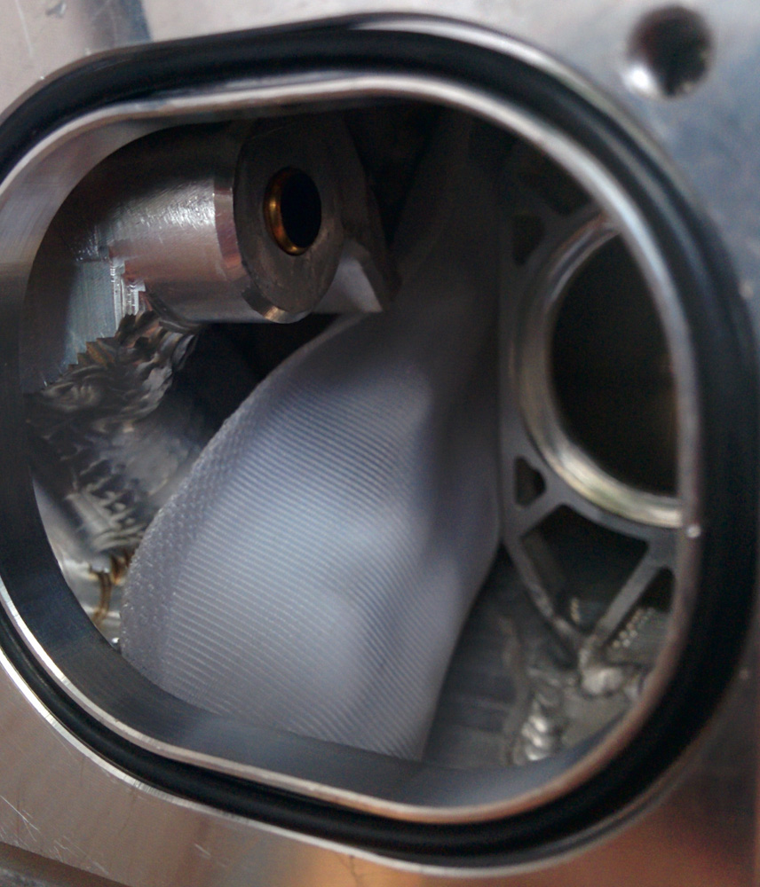
With only the side wall missing, the fuel pump could now be test-fitted. I’m happy to report that it works just as I hoped, the pump is held in place with a small amount of pressure on the O-rings.
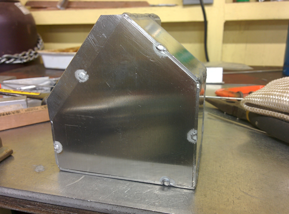
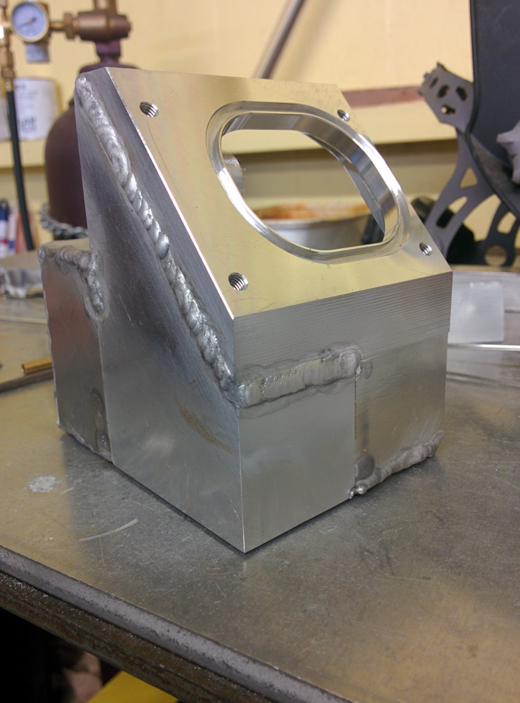
The last piece was a tight fit and had to be sanded down a bit on the upper right edge before it could be squeezed in and tacked in place. You can see that the bottom has warped a bit where the pump holder was welded in, but it’s not too bad. A little squeeze and a final tack held that in place.
This side obviously had to be done without the aid of the copper bar, since there’s no longer any way to get to the back of the weld. I was a bit apprehensive but maybe the practice from all the other sides paid off because it went fine without it.
With all the parts welded in place it was time for the test: would it leak. I filled it up with water and was dismayed to see water dripping out in several places! It’s kind of hard to see where the water is coming out though, so it was more efficient to instead plug up the pump hole with a piece of plastic, hook up a hose to the inlet, and blow in it. Just like when you’re fixing a bicycle tire, you can see exactly where the air is bubbling out.
It turns out alternating inside and outside welds was a bad idea. If you don’t get 100% fusion when welding the parts, you’re left with a little unwelded section on the back of the weld. This normally doesn’t matter, but if you now alternate to welding on the other side, it’s possible for this to become a “channel” from the inside to the outside. This was exacerbated by the flanges I had added on the inside, because that meant there was even more of a hidden section in the middle of the weld.
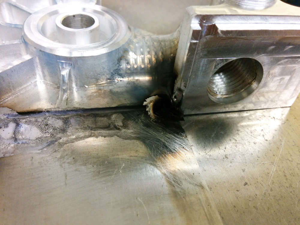
There were a couple of leaks that were easily fixed by just completing the welds on the outside. However, two leaks were in the inside corners where the inlet is. I attempted several times to seal them on the outside ends, without success. In the end I had to make those inside corner welds anyway, and it wasn’t pretty.
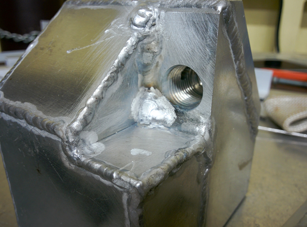
To stop the leak, I ended up having to weld the inside corners by the inlet after all. To get to the corner, you need a super long tungsten electrode and even though you’d think the argon would flood the corner pretty well, it wasn’t pretty. I screwed up several times and had to cut away the weld with the Dremel until I got to this state, which isn’t pretty but at least doesn’t leak.
Pretty or not, at least it does not leak now; I blew through the hose will all my might, but no more bubbles were seen anywhere. Since the housing won’t be pressurized more than by the height of the fuel level in the tank, that seems like a sufficient acceptance test.
After rinsing out the inside first with water and then with ethanol to make sure there aren’t any particles inside that could get sucked into the fuel pump, I mounted the fuel filters and the pump.
Before mounting the pump, I squeezed the fuel filter sock on the inside end of the inlet and addad the small fuel injector strainer to the vent hole.
So that’s it, it’s done! The only thing remaining now should be to route the hoses and run the power to the fuel pump and then we should have a functional fuel system. I sure hope the fuel will flow properly into the pump housing after all this work.
It should now be possible to start the bike and test the idle air control. There are still no linkages to the throttles, though. That’s the next and hopefully final major conversion task.
Pingback: Microsquirting the NC30, part #32: New battery wiring – Patrik's projects
Pingback: Microsquirting the NC30, part #35: Fuel supply line – Patrik's projects
Pingback: Microsquirting the NC30, part #43: A small setback – Patrik's projects