The lack of updates does not mean a complete lack of progress on the NC30 project, I’ve mostly been in “pondering” mode and haven’t really had anything coherent to say. But now I do have something coherent to say about a completely new topic: idle air control.
After the first start on EFI (hard to believe that was 6 months ago) I realized it would be really hard to not have a way to control the idle air. The choke on a carb does two things: it richens up the air/fuel mixture, but it also lets in extra air. The extra air is needed because otherwise the idle on a cold engine, even with a richer AFR, would be low enough that the engine would tend to stall. With EFI, the enriching of the AFR is done automatically based on the coolant temperature, but without a way of also giving the engine a bit more air when cold it would likely be necessary to set the amount of idle air so high that the idle when warm would be annoyingly high. (And a high idle also makes the bike more likely to overheat when e.g. sitting in traffic, something the NC30 already had a tendency to do.)
So the conclusion was that I’d need to figure out how to make the Microsquirt control the amount of idle air. The devices that do this are called “Idle Air Control”, or “IAC” valves. They typically employ some sort of adjustable orifice that is connected between the airbox and the intake tracts, downstream of the throttle butterfly. There are pulse-width modulated valves, essentially a slide connected to an electromagnet that pushes against a spring, that can be controlled directly by the Microsquirt, but the only ones I could find were for cars and were far too large. Modern EFI motorcycles typically have the idle air integrated with the throttle bodies, so there were no discrete parts there I could use either.
As usual, there’s also the ever present complication of how to fit whatever system I could find into the cramped space of the NC30. There is no way to get air out of the airbox without cutting a hole in it. Then the air would have to be routed through the IAC valve, and then split up into 4 separate connections to the ports on top of the throttle bodies. Not so easy.
Eventually, I decided that with the power of Fusion360 and the minimill, I could design and manufacture a stepper-motor controlled IAC valve from scratch. A sufficiently small design, using a tiny NEMA-8 stepper motor, could actually fit inside the airbox, between the left and right intake trumpets. This should also provide some protection from overheating the motor since there will be continuous airflow, at least as long as the engine is running.
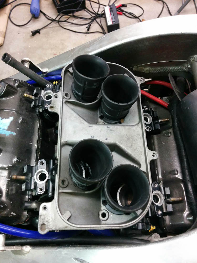
The only place it seemed reasonable to fit the IAC valve was inside the airbox, on that flat segment between the left and right intakes. The outlet will go down through a hole in that surface into the space between the throttle bodies, split up to go forward and rearward to the four ports on top of the throttle bodies (visible in the picture as brass barbs.)
To control the amount of air, the stepper motor would turn a rotor in the form of a half-cylinder, that could cut off more or less of a hole in the side of the cavity. As usual it required a few iterations to get everything packed into the small amount of space, but it worked out. These two renderings from Fusion illustrate how it works:
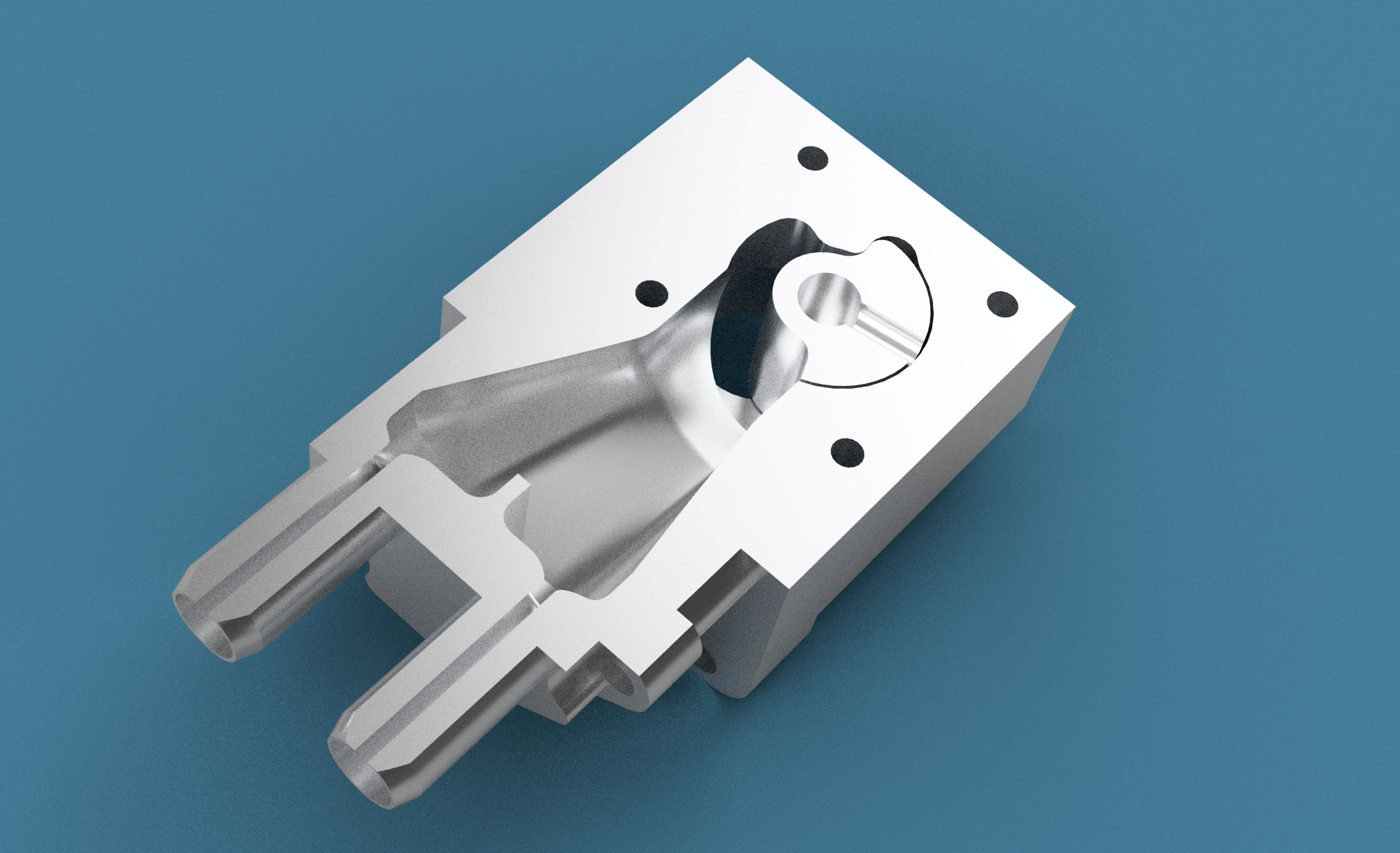
This is a section rendering of the IAC valve against the end stop in its fully open position. The half-cylinder rotor in the upper right is driven by the stepper motor (not visible), the intake is in the back of the hole the cylinder is in, and the outlets are the two barbs in the lower left.
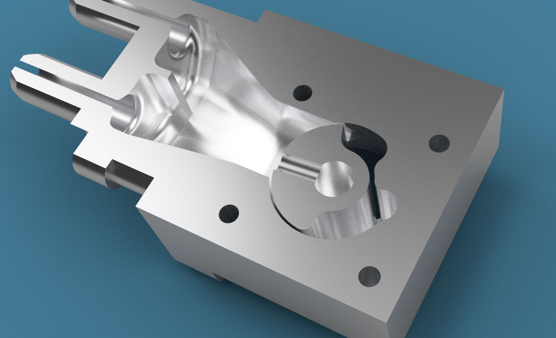
Here, the valve has rotated clockwise and the rotor now almost completely covers the hole in the side wall. The hole is tapered, and only a small opening, visible by the light coming through, remains in this position. It’s possible to completely close the hole at which point the only remaining airway is the clearance between the rotor and the wall.
Because the outlet part with the two barbs is on the outside of the airbox, it’s a separate piece that screws on from the outside, so there are three pieces that have to be made. The clearance between the rotor and the wall of the hole needs to be small, since the air leak through this area determines the minimum amount of air that the valve can be set to. This means there’s a fairly tight tolerance on the size and shape of the hole and the cylindrical part of the rotor.
I’ve manufactured all three parts, but for a number of different reasons they’re all junk. The most obvious problem was that I didn’t realize that there’s apparently no standard dimension for a “NEMA-8” stepper motor. I designed the piece from some published diagram before I had the motor in hand, and I neglected to actually measure that the motor had the dimensions I expected. It turns out both the distance between the bolt holes and the diameter of the locating circle is different on my motor, so it doesn’t fit. That would have been annoying, but the part was already ruined because of a CAM programming error that caused the drill bit to wander on two of the holes where the valve body will screw to the airbox.
It was still useful as a prototyping exercise, though. Here it is:
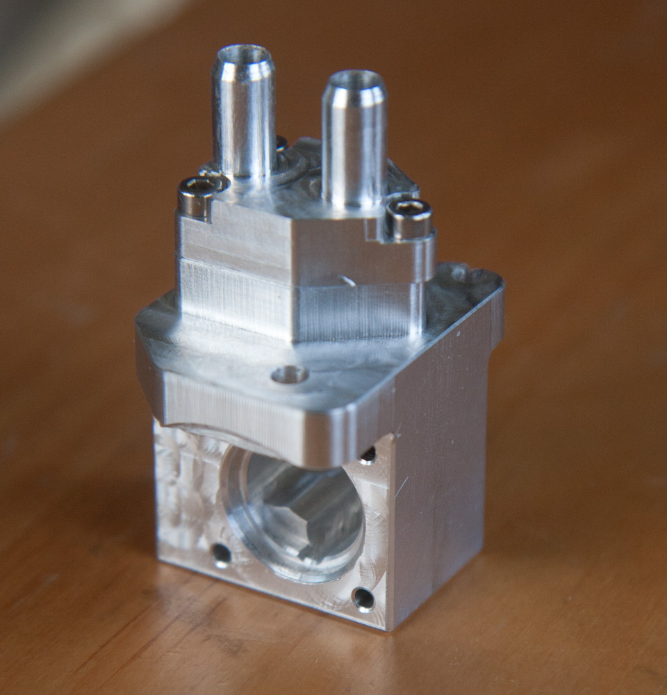
The body of the idle air control valve. The outlets are on the top and the large hole is where the stepper motor mounts. To give you an idea of how small this thing is, those bolts attaching the outlet part are M2.5.
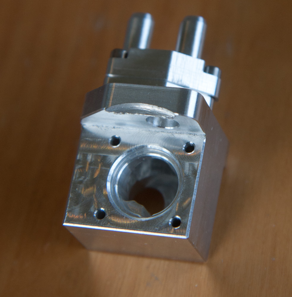
A better view of the hole for the valve rotor. The hole visible in the back is the air intake. Note the gouge on top of the piece — another CAM error…
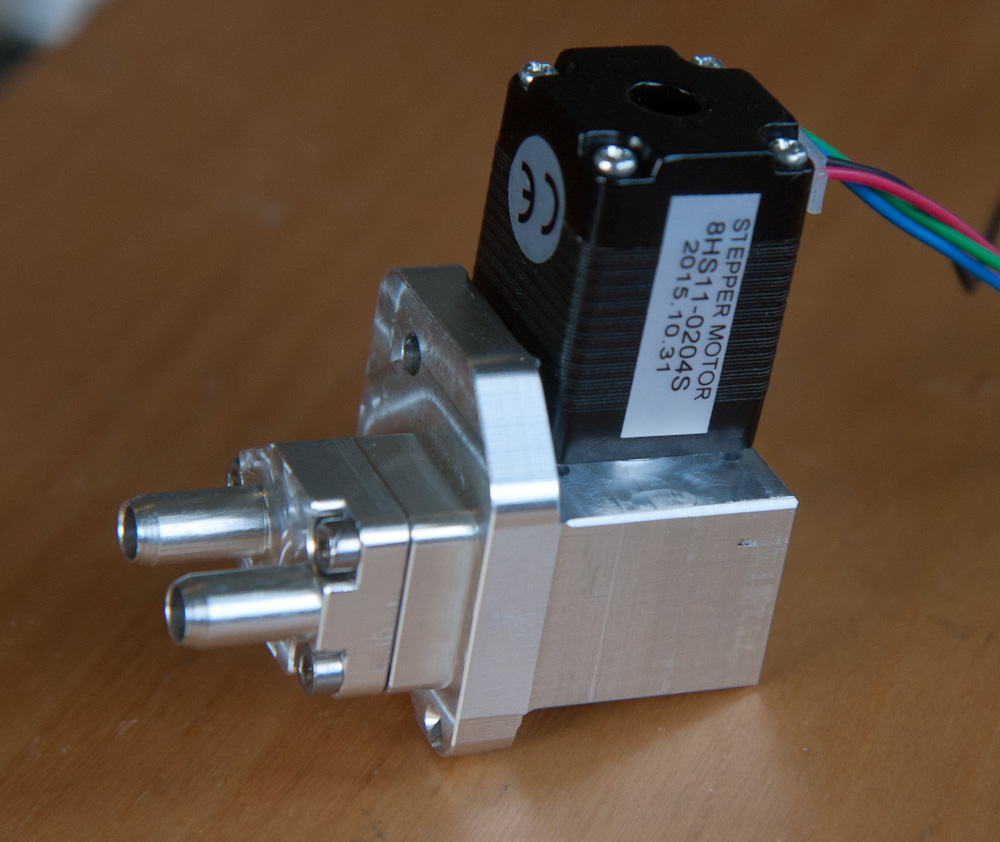
This is how the stepper motor mounts. Note that it doesn’t actually fit correctly, because the locating hole in the valve body is too small.
The rotor is also no good. To ensure that the outer profile was perfectly cylindrical, I made it by mounting a short length of 0.75″ round 6061 stock in the mill spindle and turned it down with a lathe tool mounted in the vise, sort of using the mill as a lathe. This worked well. Then I mounted the part in a V-block, located the center, and drilled the hole for the motor shaft. However, it’s still about 0.25mm off center, which is more than the clearance to the side of the hole. I don’t know if this is because the drill wandered when drilling the hole, if I failed in measuring the center, or if the drill somehow lost position. Backlash in the mill means that the exact position will depend on which way you go to a point, but the backlash has been measured to be well below 0.1mm so that shouldn’t be a factor.
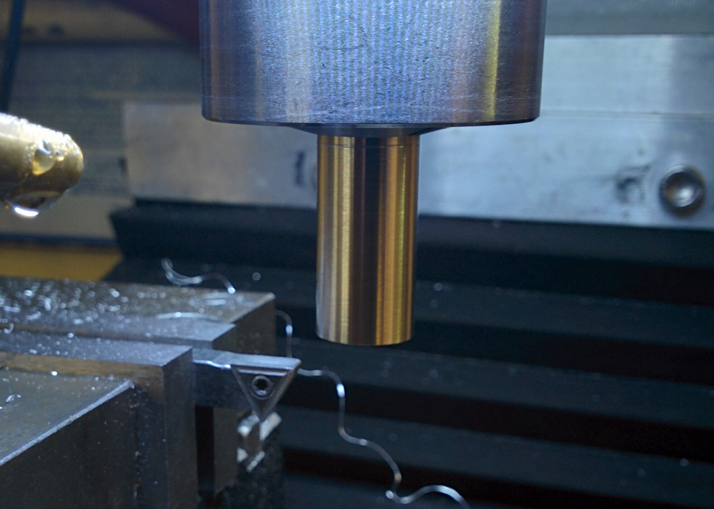
Turning the cylinder that will become the idle air valve rotor on the “mill-as-a-lathe”.
If I had a real lathe, I could drill the center hole along with turning the outside, but I don’t. I could align the spindle of the mill-as-a-lathe with some point and mount a fixed drill bit there, but I don’t think I can do that with higher accuracy than I can align the mill to the workpiece. What I will do differently next time is to at least locate the center by making a small hole with the mill-as-a-lathe. This should provide a precise starting hole. We’ll see how it goes.
So that’s the mechanical side of the task. There’s also the electronics. While the Megasquirt firmware can use both PWM and stepper motor idle air control valves, the Microsquirt doesn’t have the hardware to control a stepper. This shouldn’t be a problem since I’m already using an Arduino to read the wideband oxygen sensors and drive the tachometer. It shouldn’t be a big deal to also make it read the desired IAC valve position from the Microsquirt over the CAN bus and then run the stepper motor to that position.
An extra complication was that I had already appropriated the Microsquirt’s IAC valve PWM output to drive the coolant temp gauge (since the idle air position is controlled by the coolant temp, I just needed to determine which PWM values corresponded to the desired gauge readout and program the MS with that “idle air” table.) However, I was now actually going to use the idle air control for its intended purpose, so the coolant temp gauge also had to be driven by the Arduino. No big deal, that’s also available over the CAN bus and driving a PWM is trivial.
That is now all done. I added an “EasyStepper” stepper motor driver to the circuit board, soldered a bunch of more wires onto the Arduino pins (since I didn’t anticipate using them, they’re not connected to anything on the board) and completely rewrote the Arduino code which had become really messy. Now it’s much better structured, you can add things you want to execute periodically to an “event loop”, the things using inputs coming from the CAN bus are loaded up with the memory locations where they can find what they want, etc. If you are interested, the code is in my Arduino library on BitBucket.
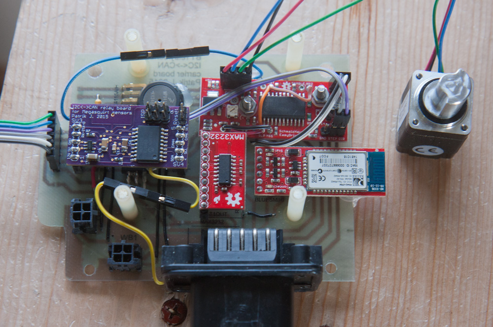
The Arduino circuit board is getting quite messy. The new “EasyStepper” stepper motor driver is in the upper right, and lots of new loose wires have been added to hook it and the coolant temp gauge up. I’m already planning how I’m going to redo this…
The circuit board has gotten pretty messy, though. It’s clearly showing its “prototype” nature. Once this is all working, I’ll probably design a completely new, cleaned up, board and get it from OshPark.
But this all works! The stepper motor responds to the commands from the MS. Check this out:
There are a few things that remain, apart from obviously making a new IAC valve body. This has mostly to do with exactly how to route the hoses from the idle air valve to the throttle bodies, without interfering with the throttle linkage, but I’m pretty happy with how this is turning out.
Patrik,
When I was building up my GSF400 project I bought/found (in you-pull junkyards) bits of equipment that I thought might be useful for creating an Idle Air circuit for the engine. But I never installed any of these parts because as I got the engine running I discovered that it had plenty of air flow for idle with its throttle plates closed. It turned out that the air flow with closed throttle plates fell right in the range that I needed for a reasonable 1,300 RPM idle only by commanding small changes in ignition advance and fueling.
I have the throttle “stop” set so that, to the naked eye, the plates don’t even appear to be held open at all, but I’m sure there must be just the slightest gap there for airflow. Also, my throttle plates (the standard Mikuni BST32 parts) have a tiny hole in them (just above the bottom center).
Obviously with its stock ignition system and the ancillary demands on intake airflow of its original carbs the GSF400 engine couldn’t/wouldn’t start up and sustain engine operation from cold good with closed throttle plates. But it appears that when I modified the carbs into throttle bodies by blocking off all of the carb-related passages (including the Choke circuit) and situating the injectors in the optimal position (just beyond the throttle plates) the closed-throttle airflow and fuel atomization became much more efficient.
And with just a bit of fiddling and luck I quickly found a very slight (almost non-existent) throttle stop setting that tuned the amount of idle air admitted to a point that hits a sweet spot. This has allowed me to only use ignition advance and fueling changes within that basic (static, fixed) airflow setting to make the bike reliably start up from cold on the first press of the button and idle at 1,300 RPM in temperatures ranging from the low 20s to 100 degrees F. It does this without any odd air/fuel ratios and it responds very well to throttle inputs while it is warming up.
I keep coming back to your project website, wondering about your planned setup because you have even more diameter in your throttle bodies (your 34mm vs. my 32mm = 106.8mm circumference vs. my 100.5mm ) which I can only imagine would result in a higher level of airflow, I’m imagining there’s probably a natural base-level of leakage that occurs around the perimeter of fully closed throttle plates, which would put your engine’s cylinders even closer to the amount they will require to sustain cold start-up idle RPM. Also, do your GPz1100 throttle bodies have a little “leak hole” in the throttle plate like my BST32s?
Based on my experience I keep thinking you could easily go without any sort of Idle or Aux air input on the engine.
Maybe… In their original configuration, the GpZ1100 throttle bodies have a mechanical adjustable stop and “fast idle” lever. However, that’s part of the bracket that held them, which of course I can’t use with the V4 engine. Without those stops, there is very little leakage (and there are no holes in the plates.) When I ran the engine, it idled very high with the extra intake ports wide open but when I plugged them up, it didn’t run at all.
So, I don’t think I can get away without either a separate idle air passage or designing some form of adjustable, mechanical throttle stop. Given the complexity of just getting a throttle linkage to work well on a V-engine, I don’t want to also be faced with making sure I can adjust all 4 plates to that amount of precision. (Plus, if you’ve ever tried to synchronize the carbs on an NC30, you’d know that’s not a pleasant experience. I’d like to get as far away from that need as possible… 😉 I think using an electronic solution is much more flexible and won’t require me to take the whole intake apart to make the inevitable adjustments.
Pingback: Microsquirting the NC30, part #28: More Idle Air Controller – Patrik's projects
Pingback: Microsquirting the NC30, part #31: Finishing up the fuel pump housing – Patrik's projects