Filament storage part 10

After 4 sides of the box were assembled, it was just the top left. This should have been quick but was delayed by the need to first bond the bracket that will hold the circulation fan to the inside surface.

Had I designed the box today, with the intent to use the bed heater, I would have made it 10mm taller, since now there is basically no space between the heater bed and the top and bottom of the box. The circulation fan must be mounted quite far back in the box to not obstruct the filament spools (it will still prevent that section from fitting a 3.5kg spool, but 1kg spools and smaller will be fine) and this means even the single ply of its mounting flange had to be cut down to not protrude into the tiny space between the heater bed and the box ceiling.

Once the fan mount had cured in place, I smeared micro on the edges of the box top, slid it in place, and weighted it down with some aluminum stock. Before adding the corner tapes, which would preclude me from weighting down the edges, I wanted the micro to cure and hold it in place.

Adding the corner tapes was a bit more unwieldy now that only one side is open, but not a big deal.

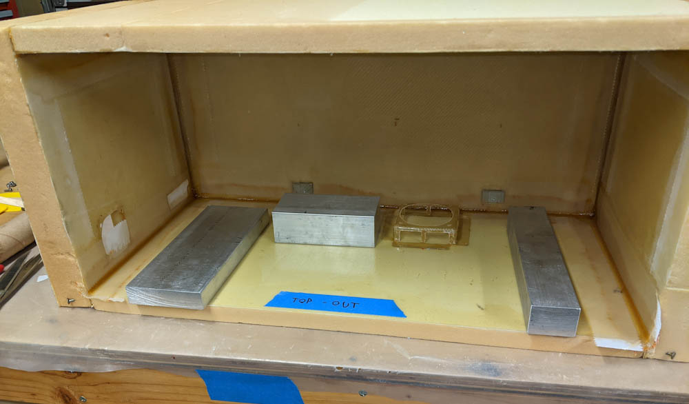
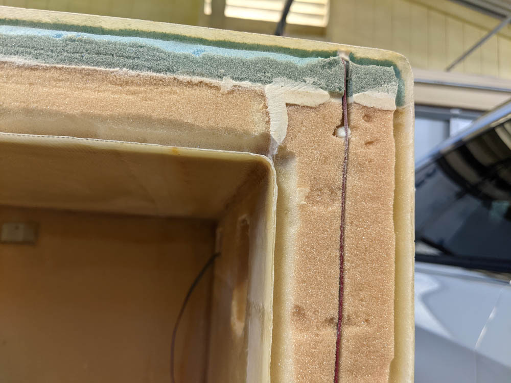
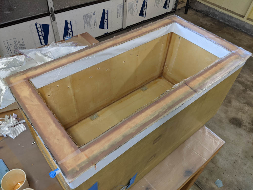
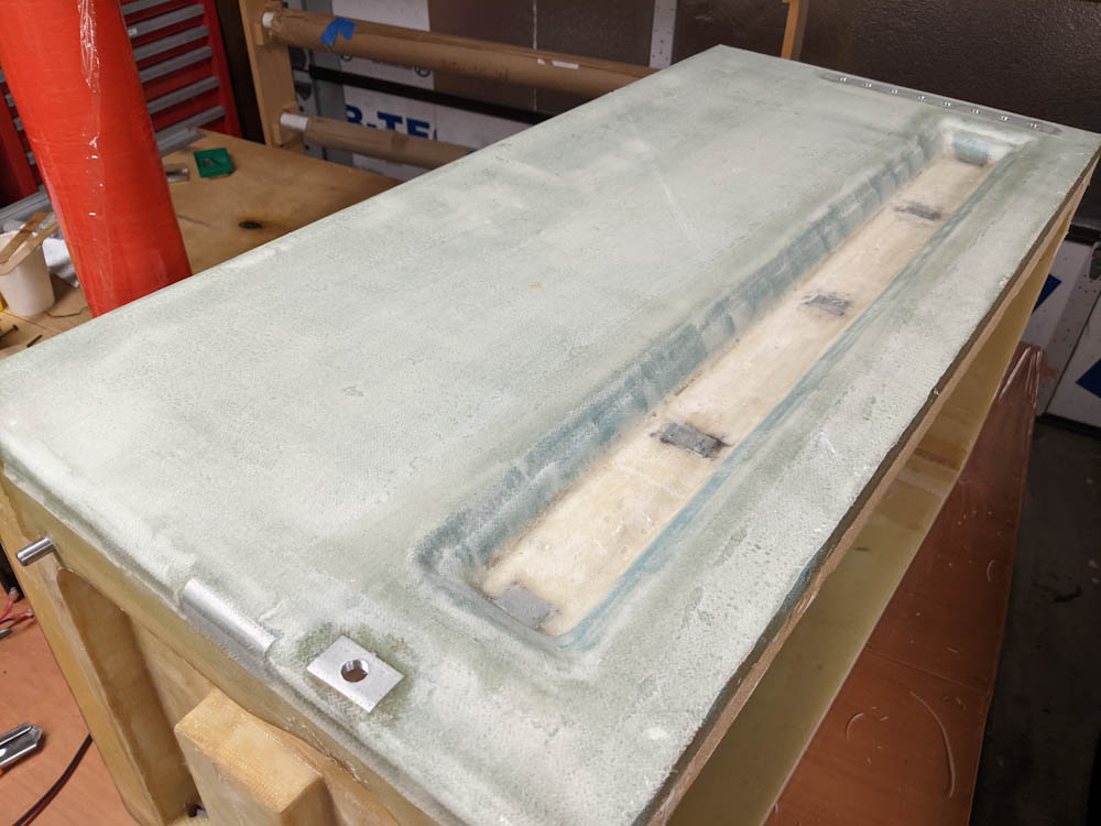
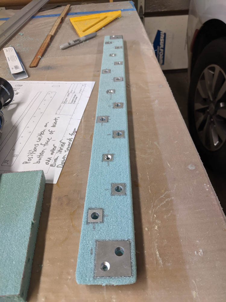
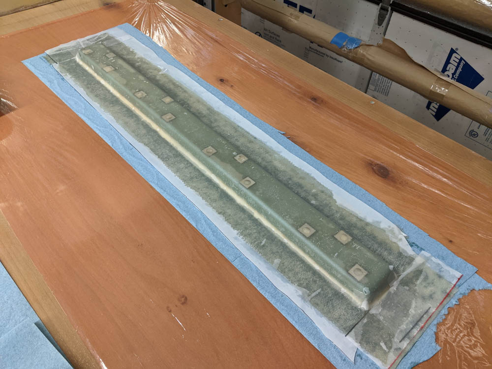
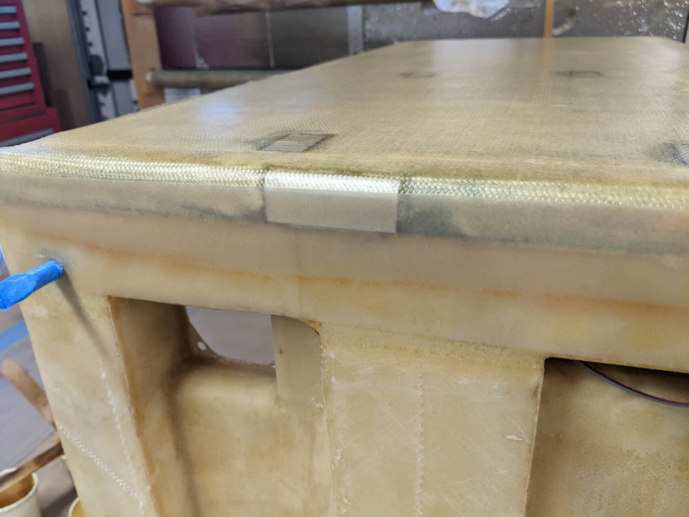
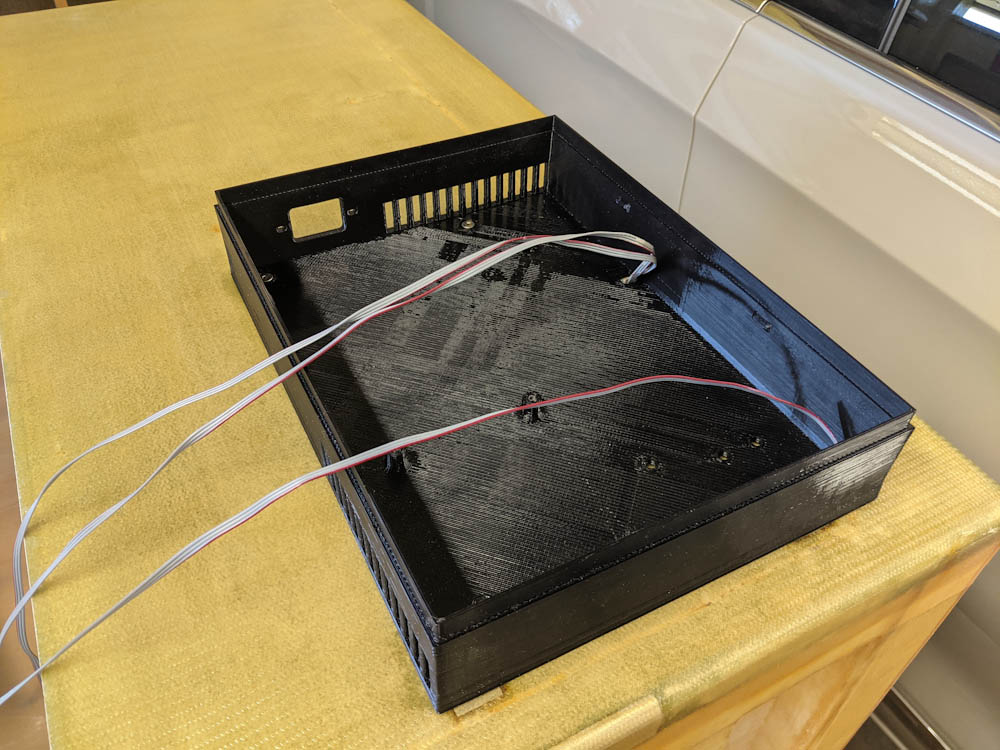
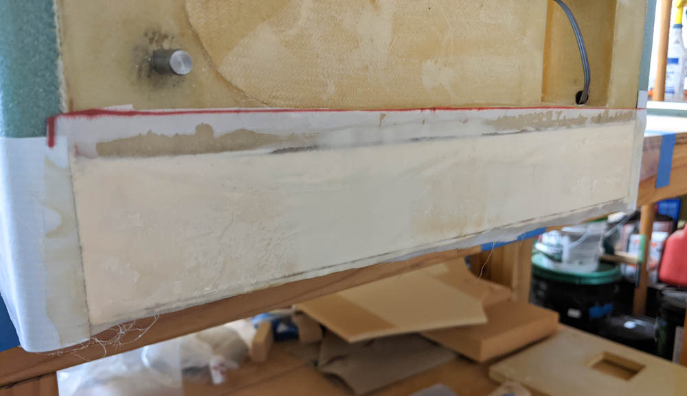
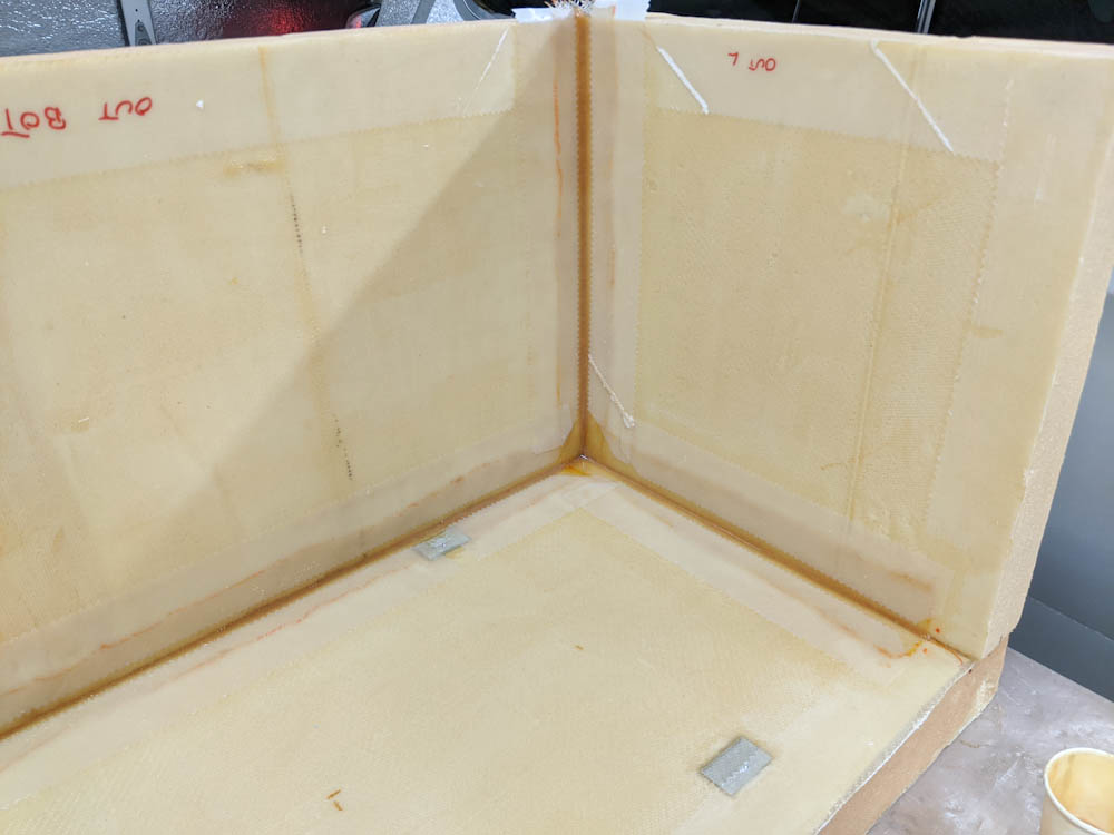
The top of the box (flipped upside down) has been bonded to the rest and corner tapes applied.

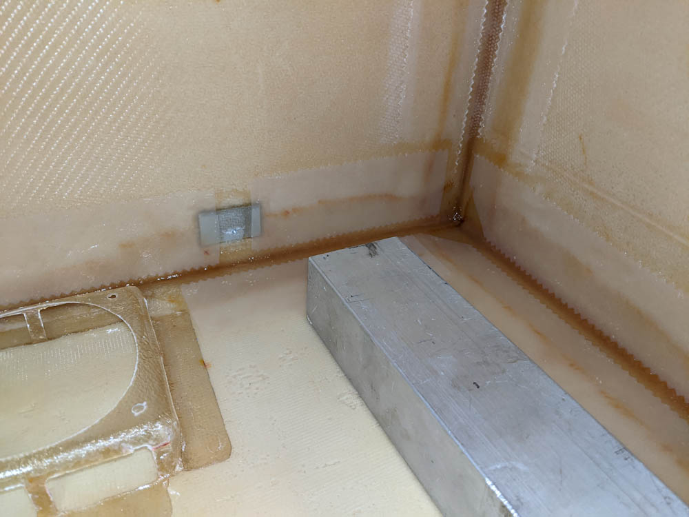
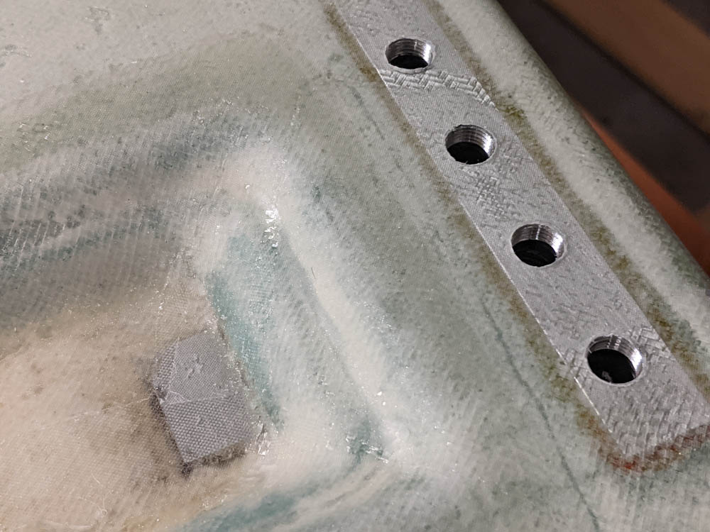
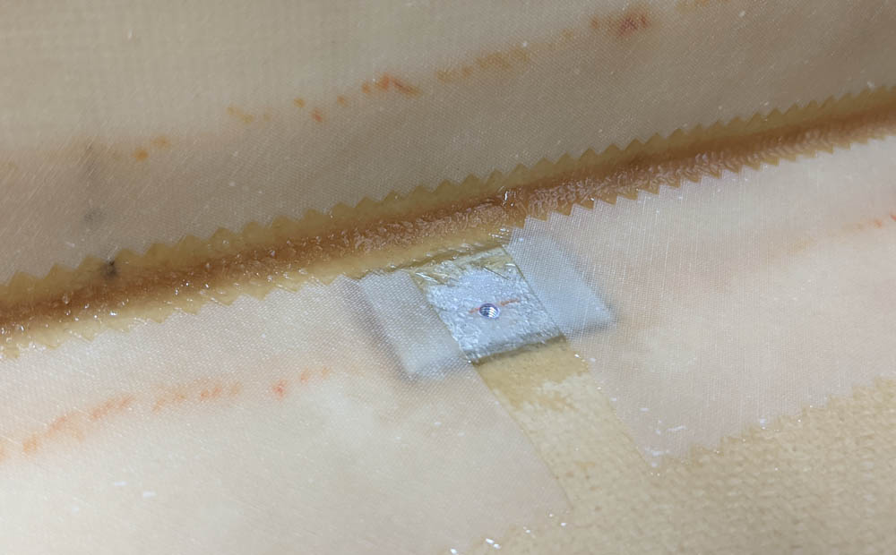
A closeup of the corner tapes for the box top. As with the bottom, I had to take care to not get epoxy in the threads for the heater bed mounting screws.

I had initially cut 1″ thick foam pieces for the top and bottom. Since then I realized that it’s pointless to skimp on foam thickness since it’s just going to lead to unnecessary heat loss and more power use, so I’ve been planning to add an extra foam layer to the tops and bottom.

I don’t have enough of the tan urethane foam left, so I had to start using some of the much stronger (and more expensive) PVC foam that is meant for the Long-Ez structural parts. They come in 3/4″ and 1-3/4″ thickness so by adding a 3/4″ layer to the tops and bottoms those will end up 1-3/4″, which seems reasonable.

The way the sides overlap, these foam pieces will also cover the edges of the 2″ vertical sides. These edges were quite uneven (it’s hard to cut the 2″ foam precisely at a right angle) so it would also cover those imperfections.

But before adding that, I also needed to figure out how to get the wires from the controller into the box. There are three penetrations needed: One into the main compartment, for the heater, the heater bed thermistor, and the circulation fan. Another into the dehumidifier loop before the thermoelectric cooler, for the dehumidifier fan and one of the SPI temperature/humidity sensors. And finally one for the second temperature/humidity sensor after the cooler.

One possibility would be to glass in some sort of tubing, maybe PTFE, so that the wires can then run in those. Trouble with that idea is that PTFE tubing is kind of stiff, doesn’t stick to the epoxy, and in any case I don’t have any in the size needed to fit all the wires.

I decided to try another method. Instead of embedding tubing, I could use tubing just to make a channel in the micro, and then remove it. I have some 3/8″ tygon tubing left over from water cooling the computer. This has an OD that’s about what I need for the wiring, is really flexible, and is also not a material the epoxy will adhere to. Worth a shot.

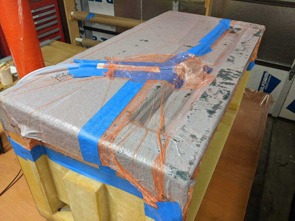
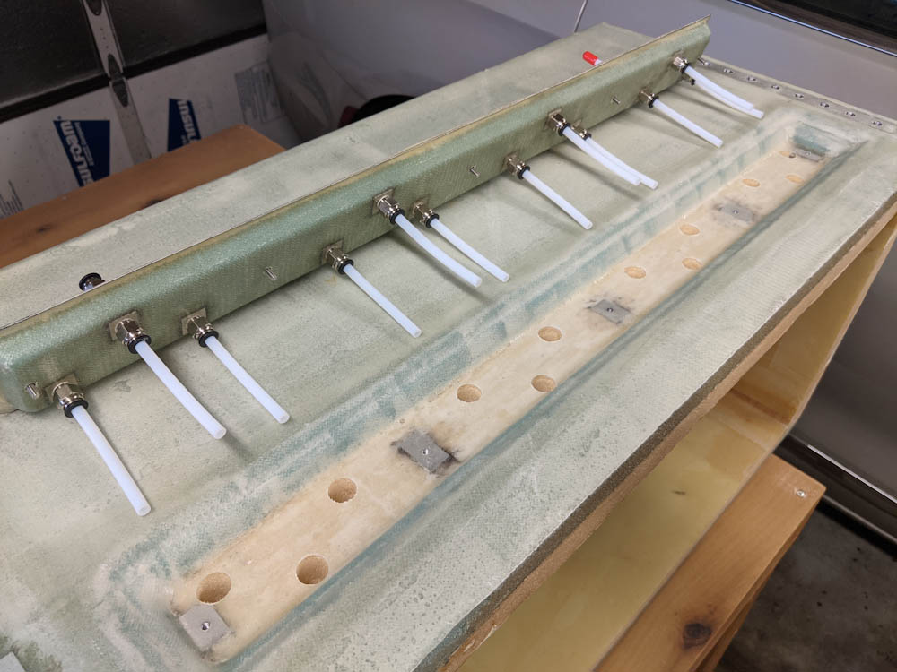
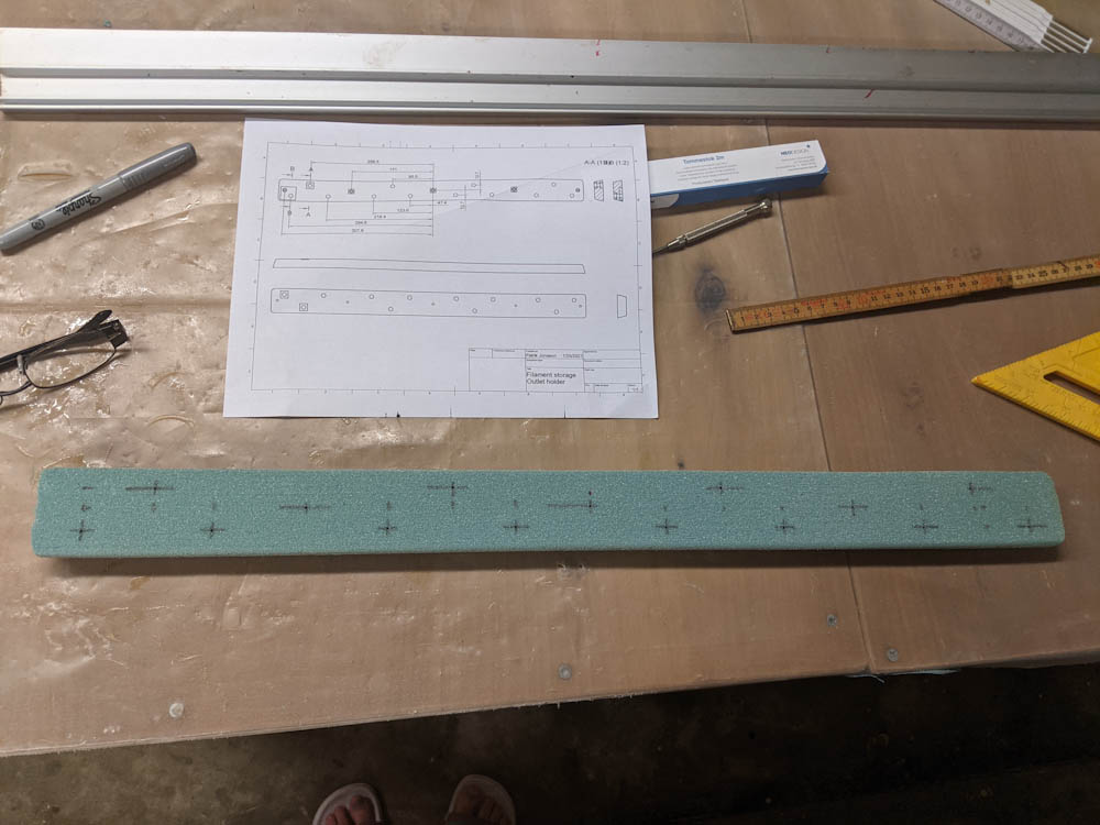
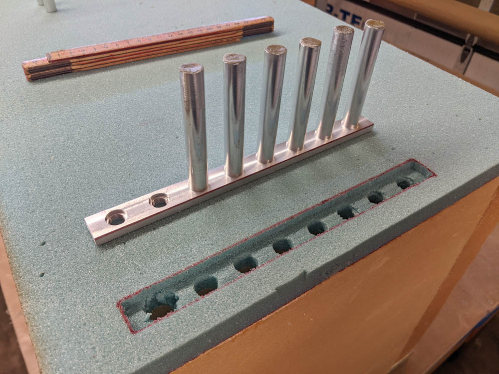
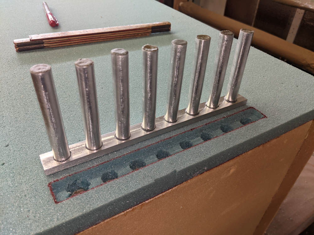
The box top with cutouts for the electrical wiring, ready for the extra foam layer.

Two of the penetrations are simple, straight shots through the wall. The one to the dehumidifier fan, though, has to pass inside the wall for a while to get to the location where the entrance hole in the enclosure will be located. I drilled a hole up to the top of the side foam, and then removed foam along the top so the tubing would fit under the new foam block once it was added.

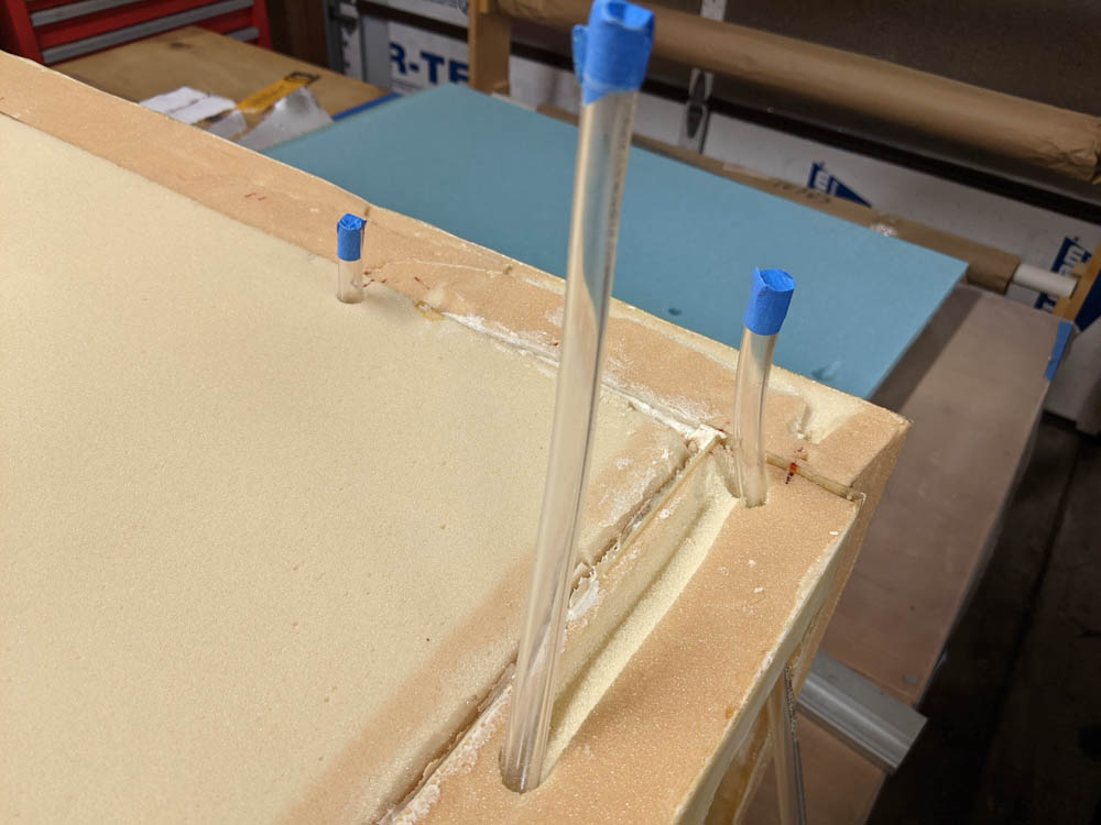
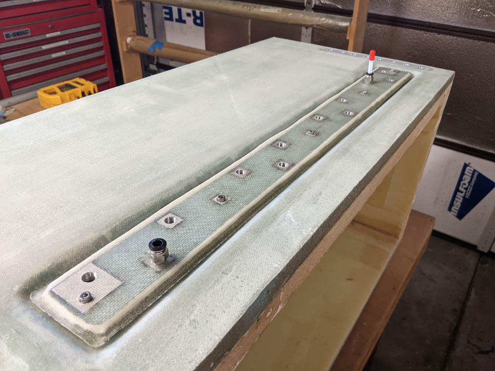
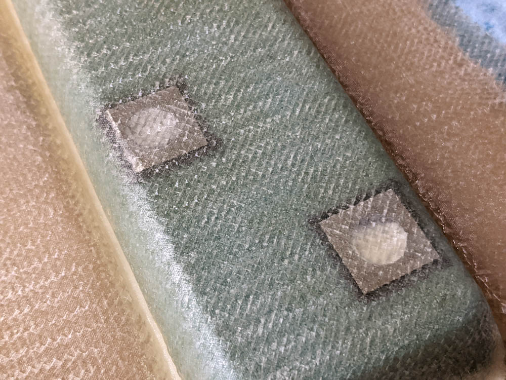
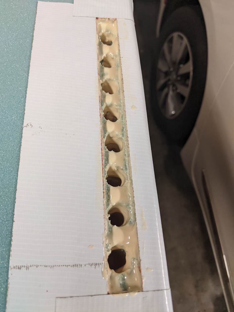
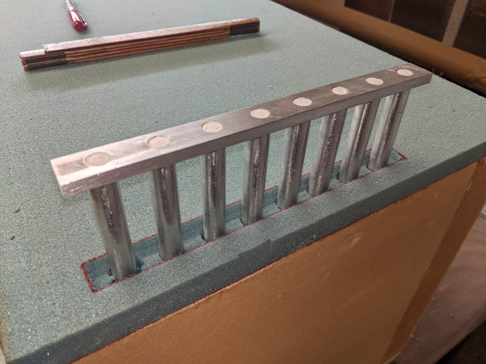
Closeup of the three sections of tubing that will create the holes for the wiring once the space around them is filled in with micro.

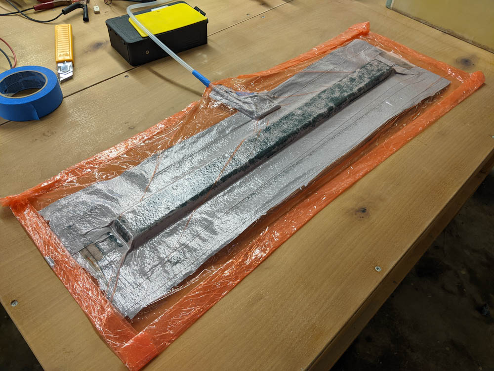
Actually bonding the foam block in place turned out to be quite a job because of the very uneven top that required a lot of filling. (In fact, there was so much filling that I’m now out of micro.)

I started the process by pouring micro slurry down the wire holes to give it maximal time to sink all the way down and get into all the places around the tubing. But it turned out I was mixing micro and filling for pretty close to 2 hours so there wasn’t much concern for that.

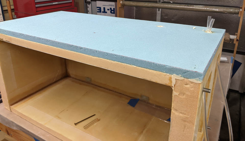
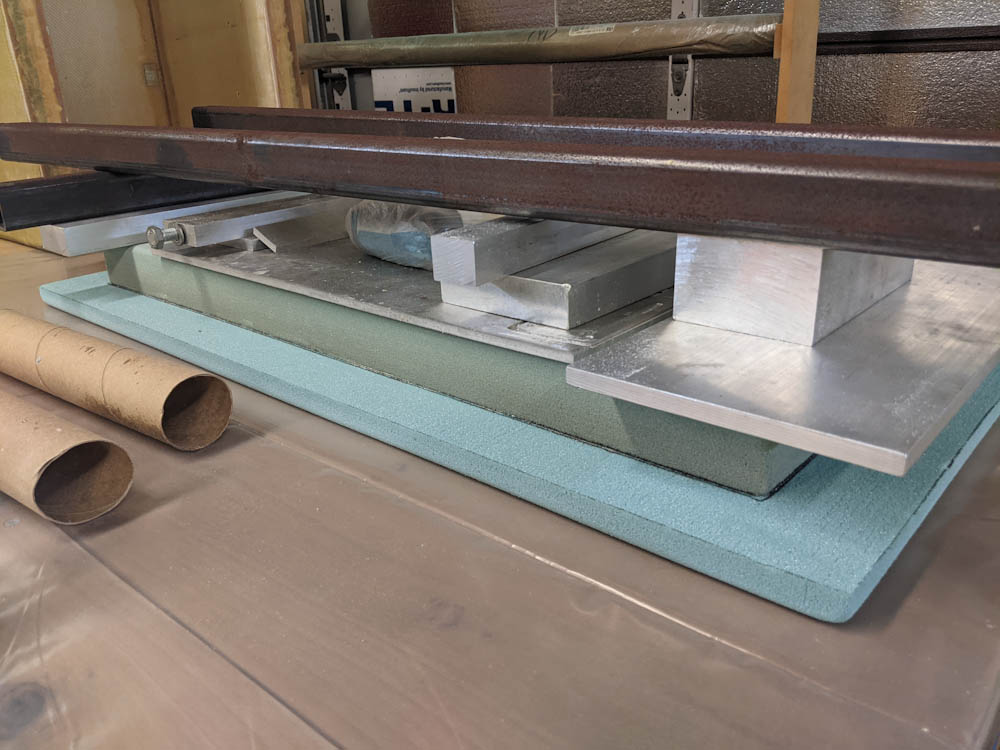
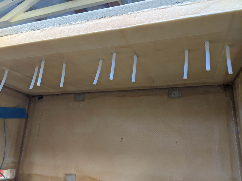
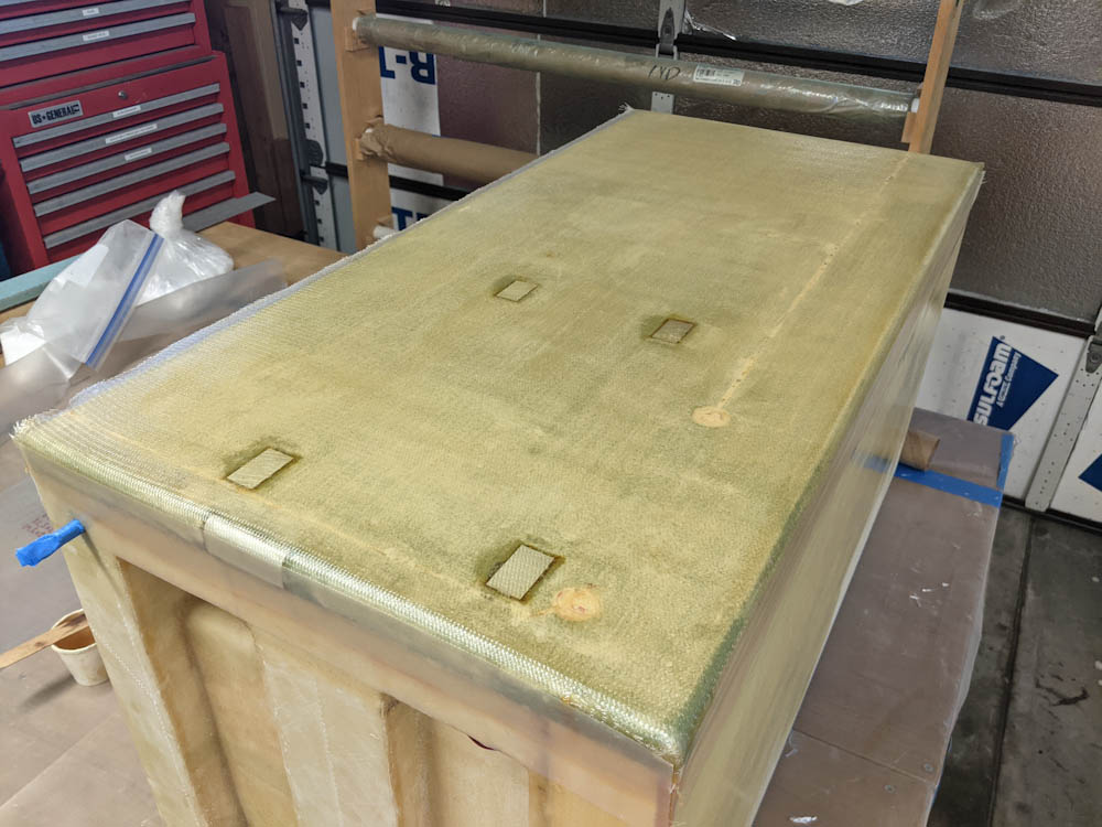
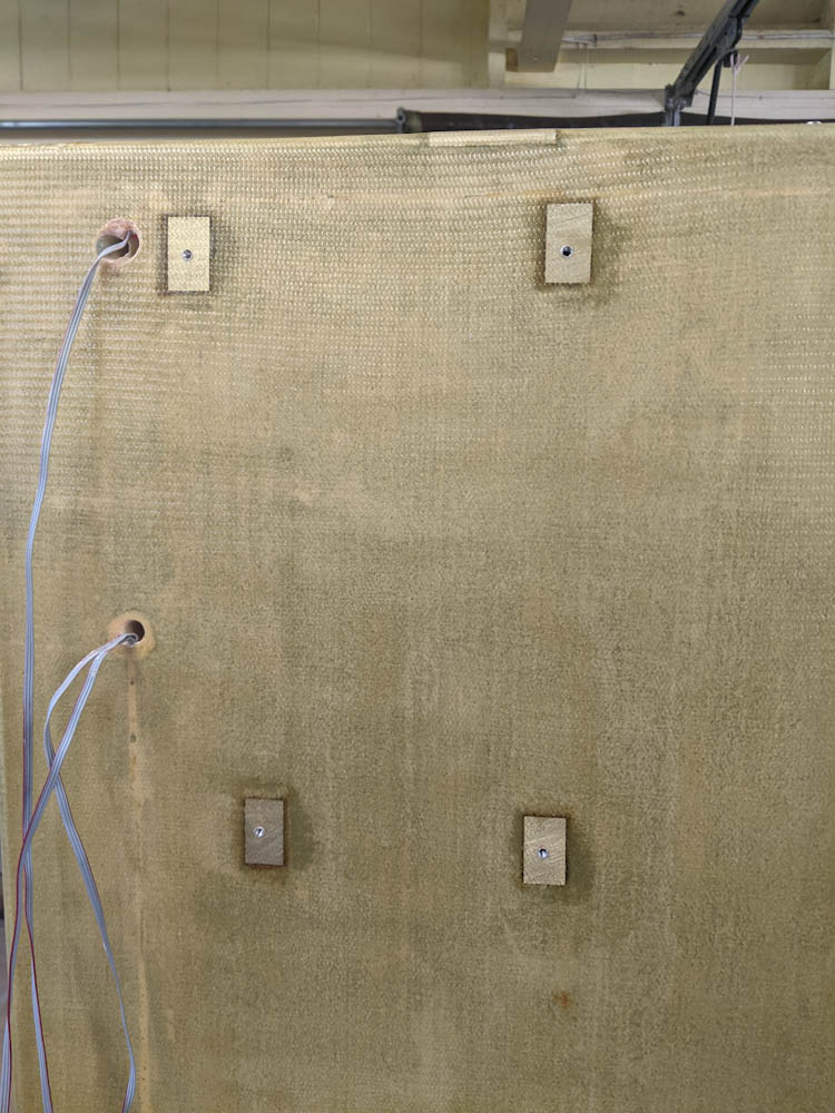
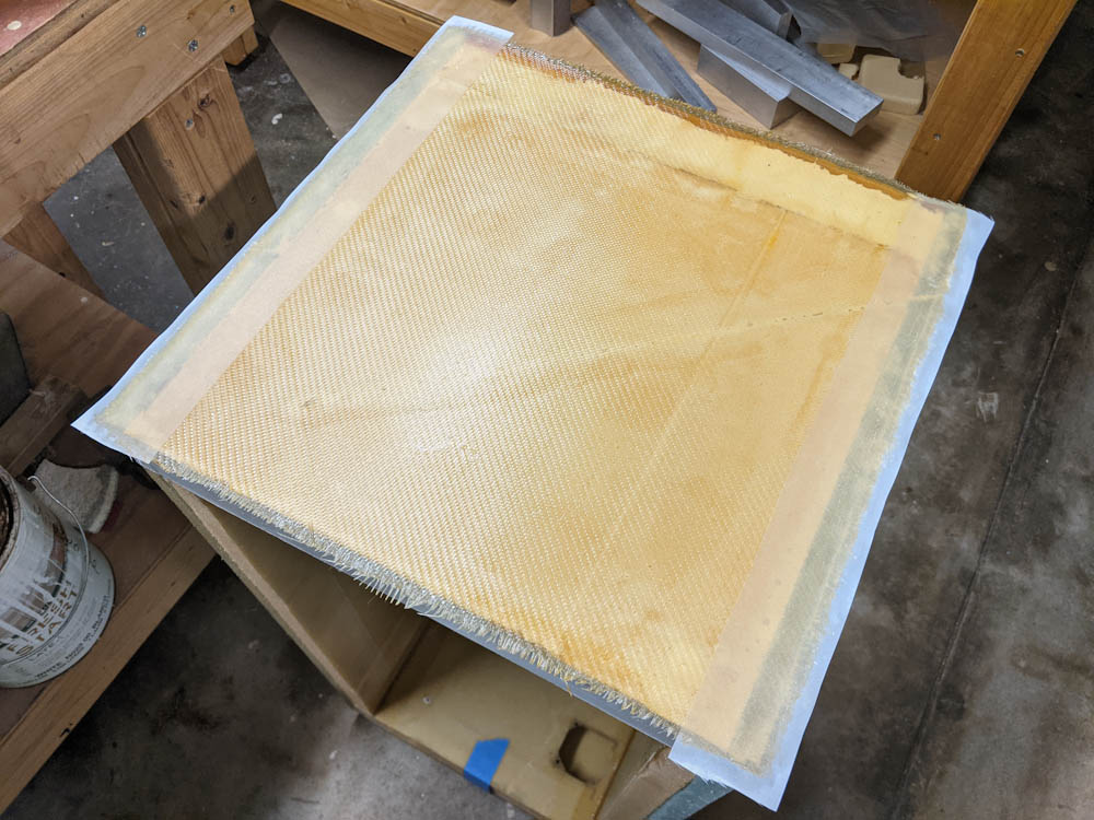
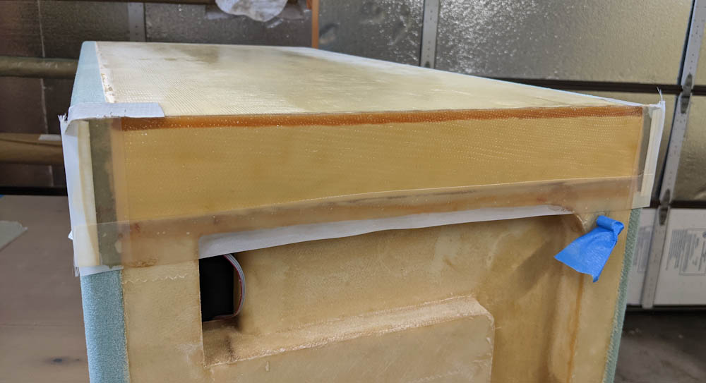
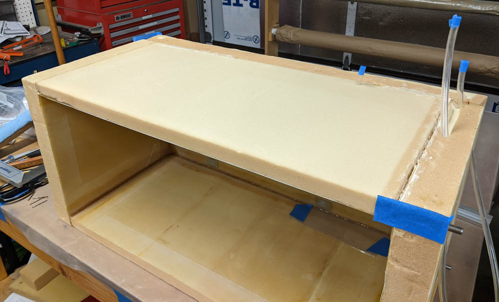
The extra layer of foam microed in place on top of the box. This is after all the weights and clamps holding it in place were removed.

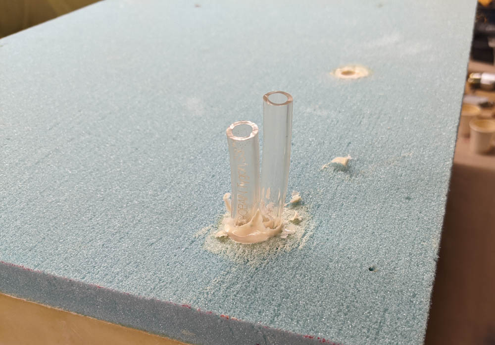
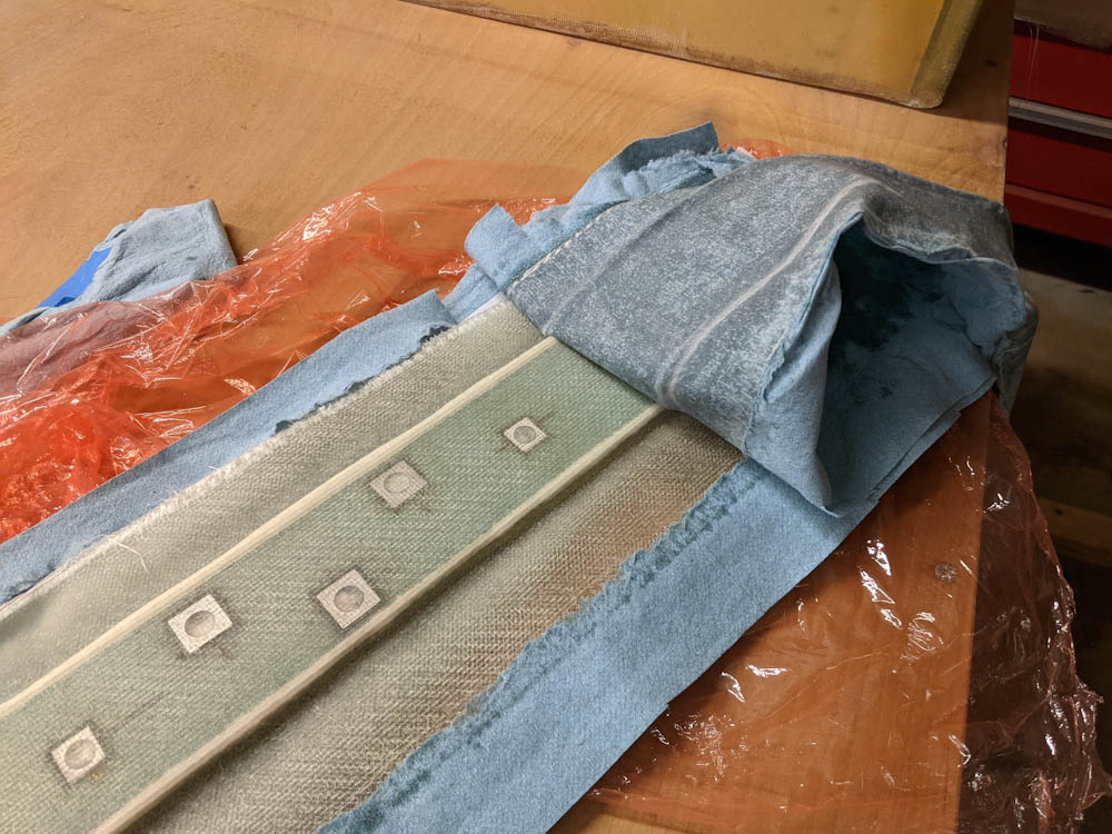
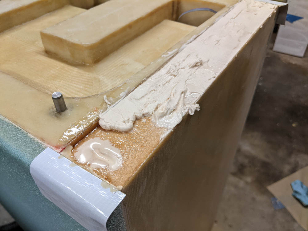
The sections of tubing poking out of the foam block. The lone piece at the back has already been removed.

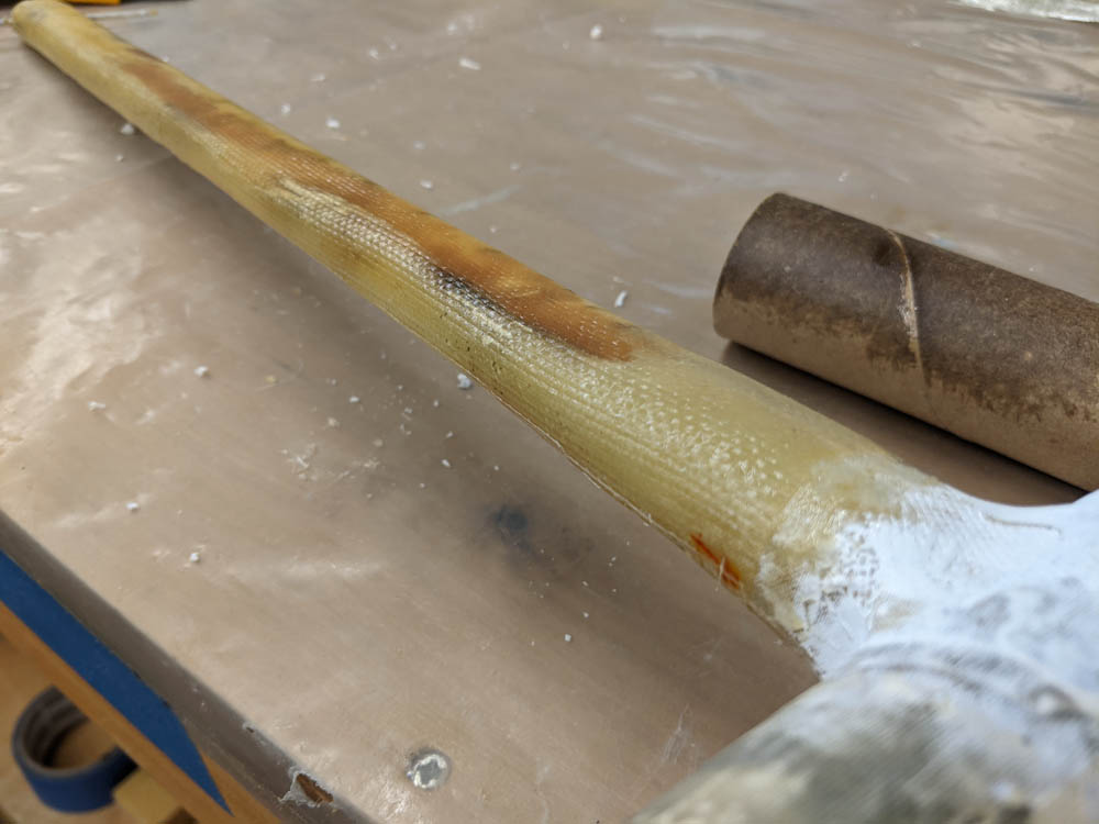
Once everything had cured it was time to see of that tubing would actually come out like I hoped. It turned out to not be a big deal getting the two straight sections out, I basically just pulled and twisted a bit and the popped out.

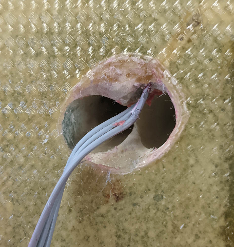
The long run, though, was a bit trickier. Since it runs in an “S” shape, there’s no way to get good leverage on the middle section, and even some quite violent pulling and twisting didn’t seem to do anything. I got the idea to spray a little bit of WD-40 in between the tubing and the micro, and that did the trick and it popped loose quite easily.

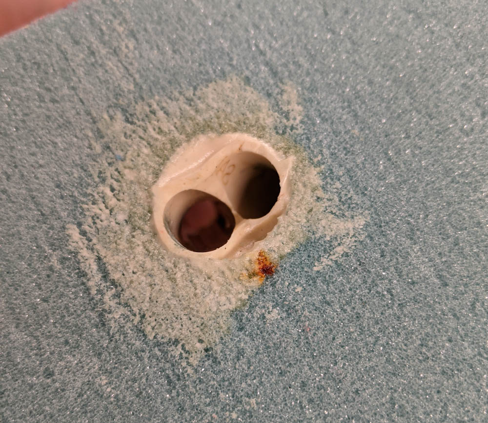
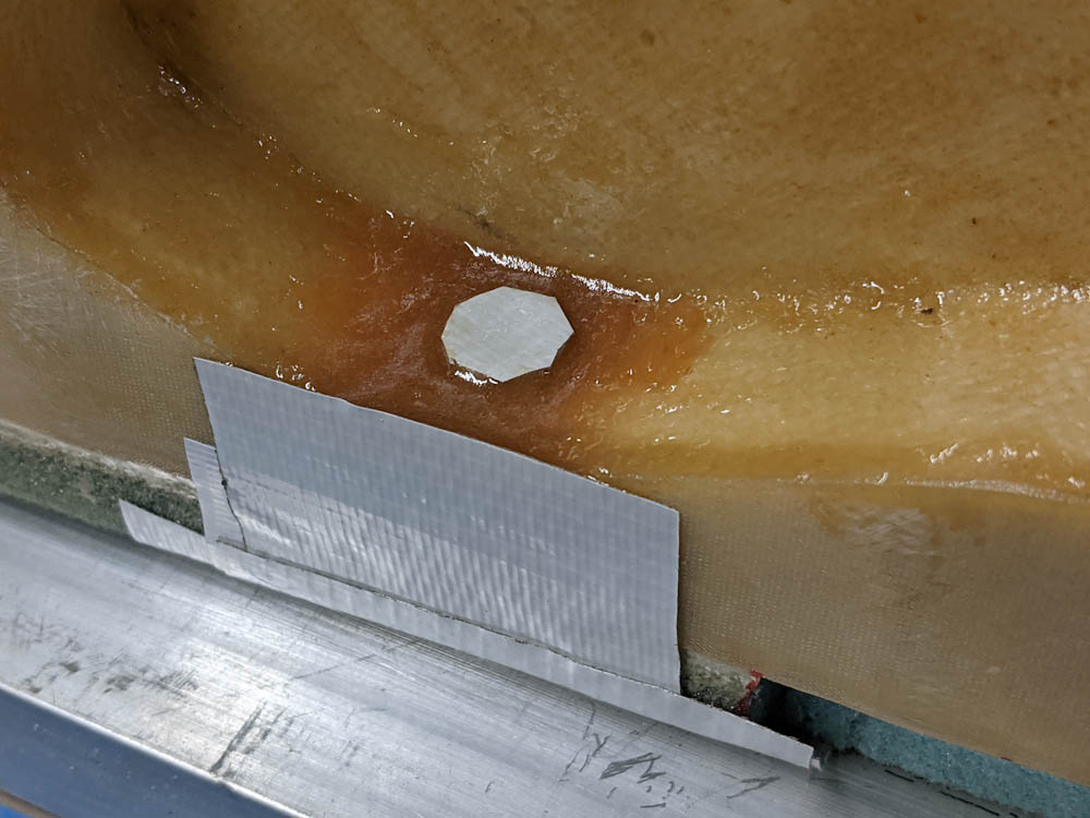
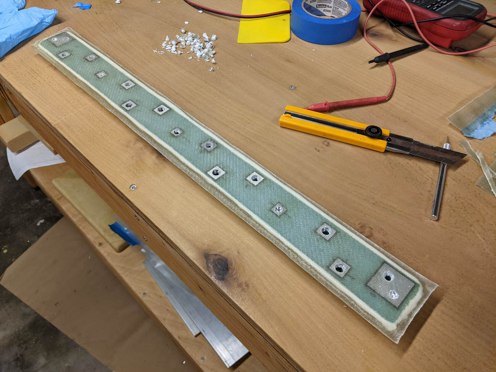
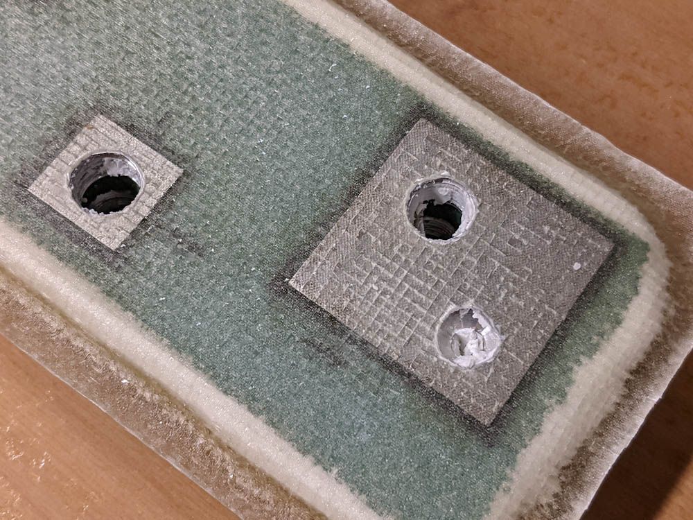
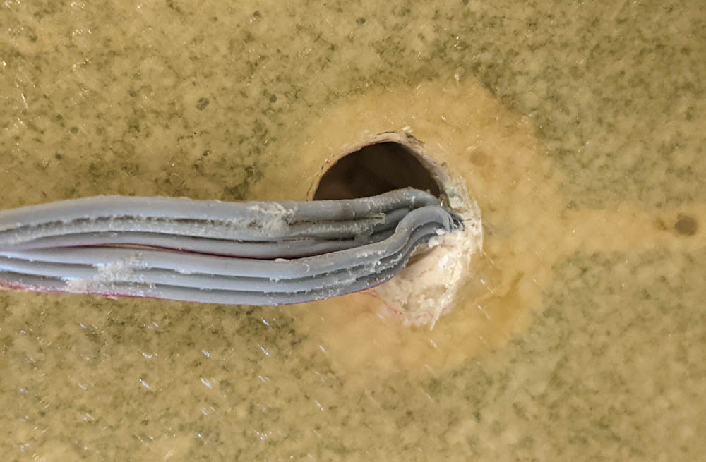
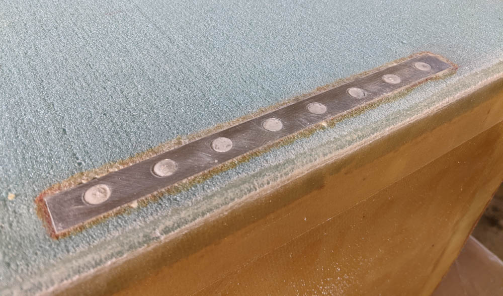
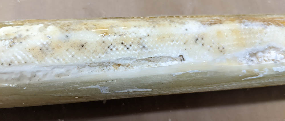
The two wire penetrations to the dehumidifier. You can actually see my fingers through the left hole.

Now I just have to avoid getting epoxy into those holes when I glass over the foam. I think people have successfully used a slug of silicone sealant that can be popped out once the hole is cut in the glass.

Next step is to add the extra foam layer to the bottom side. There are no complications on that side, I think, but I can’t do it until my shipment of micro arrives from Aircraft Spruce.

Filament storage part 9

After starting to assemble the filament storage box, I was distracted by the house fumigation and repairing the Flightradar24 antenna, but this weekend I finally had time to apply the corner tapes to the inside corners.

This is pretty simple, the idea is to apply a strip of fiberglass cloth to join the two sides in the inside corners. To make a smooth transition that the glass can follow, a small bead of micro or flox is used in the corner.

These thin BID tapes are cut at 45-degree bias, so the fibers go diagonally across the tape. This makes it conform to shapes much better, but also means that the strip can be stretched and squeezed a fair amount. Care has to be used when applying the tapes since it’s easy to stretch it as you push it into the corner. It’s also a bit tricky to make sure the tape ends up centered in the corner.

The 4 sides of the box with corner tapes applied to all joints. I also added peel ply to ensure a smooth transition and no sharp glass needles poking up at the edges of the tapes. The tape in the lower right is intentionally short since there needs to be room for the box ceiling on that side.

The only complication was that the screw holes for the heater bed plate are quite close to the edge, close enough that the corner tapes would cover the threaded holes. Getting epoxy into these holes would obviously be no good, so I initially covered them with pieces of painter’s tape, cut the cloth to clear the hole, and also cut the peel ply to avoid getting wet epoxy anywhere near the holes.

The corner tapes and the peel ply were cut to not cover the threaded holes that hold the heater bed.

Once these have cured, I can mount the final side of the box. Stay tuned, I hope to keep the momentum going now.


Antenna rejuvenation

Back in 2014, I built a Franklin antenna, and a small fiberglass post to mount it on our roof, to receive ADS-B broadcasts from airplanes with a flightradar24 receiver.

We recently had our house fumigated for termites, and since this involves enclosing the entire house in an air-tight tent, it was safest for the antenna to temporarily come down.

I’ve had to fix the Franklin antenna a couple of times because the wires connecting the coax to the antenna corrode and disappear. The last time I did this, I meticulously covered the ends in adhesive-lined heat shrink and then encapsulated the entire joint in hot glue. This appears to have worked pretty well. Inspecting the antenna after taking it down showed that the hot glue had gone opaque, but everything seemed otherwise unaffected by the weather.

The post that holds the antenna, though, was in horrible shape. I didn’t do this very well to begin with because I didn’t paint the fiberglass. The epoxy in fiberglass can not sustain continuous UV exposure without deteriorating, so at some point maybe in 2015 I realized that the antenna had been up there for a while and the fiberglass was beginning to look weathered. Not wanting to take the whole thing down I slathered some white primer onto the exposed parts but, since the antenna coax and pre-amplifier was mounted on it, I couldn’t get to everywhere.

Now I could inspect first-hand the effects of 6 years in the tropical sunlight and frequent rains do to unprotected fiberglass. There were actually places where the bare fiberglass fabric was exposed and all the epoxy was gone. This in turn meant that water had gotten under the fiberglass and the foam core was discolored and weathered.

The very badly affected fiberglass post. Here, I’ve sanded away most of the weathered surface save for minor black specks in the fabric pits. In several places the fiberglass was so far gone, and the foam below it deteriorated, that it was best to just sand away the fiberglass completely. These holes can be filled with flox when the surface is reglassed.

It didn’t help that I had not done a very good job fabricating the post, so there were places where the fiberglass had not conformed to the foam core very well. This produced a very convenient air gap between the fiberglass and the foam where moisture could collect.

After some serious sanding to get rid of the remains of the old paint, the weathered epoxy surface, and in places completely sanding away the badly deteriorated fiberglass plies, I could repair the part. After filling all the foam cavities with flox, and making sure to let epoxy run into the places where the foam had delaminated from the fiberglass, I added two plies of unidirectional cloth. (The previous layup appeared to be a single ply of bidirectional cloth, but unidirectional makes more sense here since it’s a beam and all the loads are in bending. I also made sure to make the layup quite wet to make sure to not get any air spaces.

One side repaired

One side repaired. The dark areas are where the cavities in the foam have been refilled with flox. This is 2 plies of unidirectional cloth. The post will now be flipped over and glassed on the other side in the same way.

The post is elliptical in profile. The tops and bottoms were in pretty good shape, but both sides were bad. Since it would be hard to fill the holes in the foam on both sides in a single layup, I did each side separately, wrapping the UND slightly around to the other side.

This time around I’m also going to make sure to put several coats of paint on it…

Filament storage part 8

Progress on the filament dryer was stalled over the summer since all free time went into the repainting of the room. The next thing to do on the box itself was to figure out a way to mount the internal circulation fan, figure out how to run the wires, and assemble the panels into a box.

I’ve been putting off assembling the box since it’s sort of the “point of no return” in case something goes wrong, and I wanted to make sure I knew how to run the wires since it’s easier to make pass-throughs through the foam boards before they’re assembled.

In the end, however, I decided that I should just make the fan mount and affix it to the inside of the box top, and then put everything together to get the project moving again.

The circulation fan is an 80x25mm fan that will be mounted vertically to the ceiling of the box, blowing air down to set up an airflow inside the box. To not obstruct the filament rolls, it has to fit fairly tightly against the ceiling, which isn’t optimal for airflow since the fan has to suck the air in somewhere.

To mount the fan, I made a square bracket by laying glass on top of a 1″ thick 90x90mm large foam piece, folding it down along the sides and then out at the bottom to make feet. By cutting out a big circle in the “top”, and then cutting most of the sides away, the fan can suck air in through the slits on the sides. The airflow area is a bit smaller that I would like, and the fan definitely has a slightly choked sound when tested, at least at full speed. However, I don’t anticipate it needing to run very fast at all since all it needs to accomplish is to make sure all the hot air doesn’t stay at the top, so I think it’ll be fine.

This is the bracket that will hold the 80mm circulation fan.

With the fan mount done, I started assembling the box. After some test fitting, tedious removal of all the peel ply, and trimming some edges that weren’t quite straight, I went for it. For starters, I assembled the left and right sides, the back, and the bottom. This is easy to do on the table, and adding the top can then be done by flipping the box upside down and adding the top in the same way.

Eventually all the inner corners will get glass tape to hold them together, but to avoid disturbing the shape when doing that I started by adding flox to the foam edges and moving then against each other to “glue” the joints together. Checking that everything was square, they were temporarily fixed in place with a few large nails through the sides. 

The box with the cured flox but no corner tapes yet. The top of the box won’t be mounted until the corner tapes are done, since it will be much harder to access the inside at that point.

This worked pretty well. It was a little hard to fit the pieces with the flox in the joints since I’d deliberately made the flox quite dry so it wouldn’t run out of the joint, and I ended up getting little gaps in places where the flox had’t conformed. That’s not really a big deal, though, since the real strength of the joints come from the glass tapes. I can also backfill the holes in the joints from the outside before glassing that.

More home improvement: Repainting the office

Last year, we stripped and repainted the blue “library”. This summer, Kathy decided that her home improvement project during the break would be to strip the lead paint from the “office”.

I moved my work setup into the blue room and she worked on stripping the paint and then the whole paint prep started again. I’m not going to go over all the details since it’s basically the same as the previous room.

Kathy started by stripping the intersection between the walls and ceiling. This is tricky because of the moulding. Some of it was also severely termite damaged as is visible on the left.

Termite damage was more severe in the walls in this room, especially the closets, and there were some planks in the ceiling that were completely eaten through. We filled most of that damage with Bondo, which is handy because it’s liquid enough that you can get it into the termite galleries.

Kathy’s going ahead of the roller putting primer in the grooves between the planks.

The room fully primed.

The house paint scheme that Kathy made up when we started repainting specified a warmer tone in this room since it’s on the north side of the house and only gets direct sunlight immediately after sunrise and before sunset during the summer months. A room with only indirect light will look a lot cooler unless the room is painted in a warmer tone that compensates, so this room was painted in “Grand Sherbert”, a color somewhere between orange and salmon.

Ceiling is done, and the first coat of the “Grand Sherbert” is on the wall.

We also replaced the old ceiling light fixture in the center of the room with four 1’x1′ 11W flat LED panels. We already use these in the kitchen and really like them. At full brightness, they provide plenty of light, but they’re also dimmable down to a very low level. They even have a switchable color temperature.

Walls are done, and we’ve also replaced the ceiling lights with four flat LED panels. Note how different the wall color looks in this picture compared to the one above.

The last thing, as usual, was to put the Eco Brilliant on the trim. (The baseboard will be painted after the floor is redone.)

Since we already had all the furniture out of the room, we also decided to touch up the floor finish, which has received some scuffing over the 7 years since we refinished the floors. , especially where my office chair had pressed the rug into it. The oscillating sander made a brief reappearance to abrade the old finish and then I added two coats of Bona Traffic HD.

After going over the floor with the 220 grid screen the old finish has been matted down, except where the coat was a bit thinner and the sander hasn’t gotten to.

This is the floor after the first coat dried. We added one more coat for good measure.

I’m pretty out of practice with the applicator, so the results were not exactly flawless, but the floor looks much better and will hopefully stand up for another decade now.

At this point, all that remains is to paint the baseboards which I left in primer to avoid damaging the paint when sanding the floor.


Transportation upgrade

Posting’s been slow lately, I hope to bring everyone up to date on recent progress soon. The first topic is that we said bye to the good old Prius and upgraded our transportation.

The Prius has been an excellent car, but its versatility dropped a lot when you always have the child seat strapped into the back since you can’t fold the seats down without taking it out. Which we need to do pretty often to take the trash to the dump, etc. (Weaksauce, I know. It must be age.)

We’ve loosely discussed getting a larger vehicle for a while, but I certainly didn’t want to get a gas guzzler. There are some pretty fuel-efficient larger options like the hybrid RAV4, but you can’t actually fit that much more in them. (I like to say that these SUVs are “large on the outside, small on the inside”!)

Enter the Pacifica plug-in hybrid minivan!

Pacifica
Our new plug-in hybrid minivan, the Chrysler Pacifica.

Once I started looking at larger options, it was clear that nothing can hold a candle in utility to a minivan. Not only do you get a massive cargo space, large enough to load 4’x8′ plywood sheets should you need to, you can also seat 7 people comfortably which is useful when the grandparents are visiting. However, minivans use a lot of gas, with one exception: Chrysler makes a plug-in hybrid version of the Pacifica minivan. This is clearly a “compliance vehicle” to avoid federal penalties because Fiat Chrysler mostly makes gas guzzling vehicles like the Dodge Challenger and Jeeps. Lucky for us! (For 2021, Toyota is finally making its Sienna minivan hybrid (not plug-in, though) so next year there will be two options.)

The Pacifica has a ~30 mile electric range, which is perfect for our around-town trips. Since we upgraded our water heater to a heat pump, we were actually consuming less electricity than our PV was making, so at the rate we drive, we basically charge it for free. This is lucky, because with utility rates as high as they are here ($0.35/kWh), Hawaii must be the only state in the country where running a car on electricity is actually not really cheaper than running it on gas!

As much as I hate to admit it, it’s really nice to have that large, cavernous cargo area. When going to the beach, you can basically change Axel into swimwear while he’s standing in the back, with access to all the gear. Throwing a bike into the back with Axel in his chair is also no problem.

So far the Pacifica is entirely stock, and I don’t expect there will be many projects associated with it. However, there is one thing I want to do: upgrade the headlights. They’re halogen, and they’re not very good. I’m not about to go cutting up brand new headlights so I ordered a second pair that I’m going to open and replace the high and low beams with LEDs. Whenever I get around to it… It’s getting darker now so hopefully soon.

Filament storage part 7

After designing the circuit board, I thought I would get back to glassing but nothing got done on that end before all the components and the circuit boards arrived.

I’ve soldered surface-mount boards before using the “smear flux everywhere and touch the pins with the solder iron” method, which works but is pretty slow and error prone. I decided to up my game by also ordering a hot-air reword station. This is basically a small hot-air gun that can accurately control the temperature and airflow. This allows you to heat up the board and components enough to melt solder. By applying solder paste (which is solder in non-metallic form which turns into metal when heated up) to the pads, sticking the components into the paste, and then heating everything up until the solder melts and flows into the joint, you can make quite good-looking boards, and the risk of bridging pins is smaller than when using the solder iron.

The solder paste is squirted out with a tiny syringe (the real way of doing it is to make a solder mask, which is a sheet of plastic or metal with holes where the pads are, so you can just smear paste across the entire board in one fell swoop, but it doesn’t really make sense making one of those for a single board) which took some practice. Especially on the small IC pads that are very close together, you can add too much paste and end up bridging the pins anyway. Once I got the hang of it, though, this was a pretty painless way of doing it.

Step one was to ensure I could get the small-pin chips soldered. This is the Atmega328 and a few of the passive components.

I started with the hardest part, the Atmega328 32-pin package, since I didn’t want to do a bunch of other work and then screw that one up. My first attempt looked a bit uncertain, when I probed the pins there appeared to be an invisible bridge between two of them. To be on the safe side, I melted it off and started over.

Once I was done with the chips, there was just a loooong list of capacitors and resistors, with a few diodes and transistors in there. It took a while to make sure I got the right component values on all the places, but after a few hours it was done.

All components and connectors mounted, ready for testing.

With all the components mounted, it was time to try to flash the Atmega328 with the wireless boot loader and set the fuses accordingly. No joy. I was wondering whether I had overheated the chip when soldering, because all the connections checked out, until I noted that I had flipped a diode. With that fixed, I got the chip flashed correctly.

Then I had to program the Xbee with the correct settings to connect to my mesh network. The requirement to be able to connect both the Atmega or the Xbee to the serial line for programming took some thinking. Furthermore, the Xbee is strictly 3.3V while the Arduino TinyUSB programmer supplies 5V. This means the power to the Xbee and the Arduino needed to be isolated, as well as the serial lines.

The solution I came up with uses logic-level converter circuits. There is an ingenious bi-directional level converter circuit that uses a single FET and a few resistors. These convert between two voltage levels and will also block signals if one of the two supply voltages are zero, so by adding two of these converters between the serial ports on the Atmega and the Xbee, with a header in between, and a jumper that determines whether the header powers the Atmega or XBee, we get all the desired features: There is no back-powering between the Atmega and XBee power circuits or over the serial pins, but when powered through the onboard voltage regulator they can communicate over the serial lines.

Finally it was time to power the 12V in and see if everything worked, which it did. Almost. One of the LEDs hooked up to the XBee didn’t work, which turned out to be another flipped diode, easily fixed.

The board powered up for testing. The two red LEDs at the bottom indicate when the heater and the thermoelectric cooler are on, respectively. The red LED in the center is the 12V power indication, the yellow at the top the Xbee association light, and the green in the upper left shows the XBee RSSI (radio received power). There are two more LEDS there that show traffic on the serial send/receive lines.

Everything works so far in that the heater and cooler output LEDs blink when turned on and off, and I can talk to the board over the XBee. I haven’t attempted to hook up any of the peripherals yet, though.

Now I really need to get back to glassing so I can assemble the box and start wiring things up.

Filament storage part 6

Lately, the glass work on the physical box has been on pause since I realized I needed to work out what the connections to all the sensors is going to look like. To work out the electronics, I buckled down and started designing the circuit board. I had a vague notion of what it needed to do but it always helps flesh out the design when you really have to put it down on a board.

Previously, I’ve designed my boards in Eagle, which I bought back in 2010 or so. However, since then Eagle has been assimilated by Autodesk and its functionality is now part of Fusion 360. Strangely enough, while Fusion 360 has no limits on its capabilities for 3D design even in the free version, the electronics design retains a limit on the board size from the free version of Eagle. I can’t use my old Eagle license and Autodesk has now taken the standalone Eagle entirely to a subscription model which I wasn’t about to sign up for. Luckily I could, barely, fit all the stuff I needed within the board size limit in Fusion 360 (I think it’s 80cm^2.)

While the Fusion 360 Electronics experience feels like the 3D design experience from 4 years ago in that it crashes constantly, the integration is pretty cool. It automatically creates a 3D model of your circuit board that you can integrate into the 3D design. I haven’t made use of this yet but I will 3D-print the enclosure for the electronics so it will come in handy there. This way there’s no question of whether the board will fit and you can even make very funky board shapes if you need to squeeze the board in somewhere.

Designing the schematic is very slow for me, since I do this rarely enough that I basically have to look everything up all the time, but I just put in the order at OshPark so in a couple weeks I should hopefully have the board here.

A rendering of the circuit board from Fusion 360. Not all components have 3D models, so the connectors and some of the components just show up as squares.

Now that I know exactly how things will be hooked up, I can get back to putting the box together with routings for the wires.


Filament storage part 5

After glassing the cover for the dehumidification channel, I needed to mount the thermoelectric cooler. Small tasks are best now….

This is the cold side of the thermoelectric cooler. This cold sink protrudes into the channel in the opposing part, forcing the air over it.

The hole fit pretty well, there’s a bit of clearance but I’ll seal this up with some silicone when mounting the cooler for real.

On the outside, I had to drill and tap the holes in the hardpoints.

This is the hot side of the thermoelectric cooler. This will also need a fan. The wine cooler I stole it from has a slanted fan mounted under it, I’ll have to do something similar.

I marked the locations of the holes by trial fitting the thermoelectric element and managed to drill and tap pretty accurately.

The thermoelectric cooler, now mounted with screws.

I’ll also need some sort of guide so the cover can be positively located in the correct position, and then some latch or something to hold it in place. I have some 8mm guide pins that are left over from the EFI project (I was going to use them for the throttle linkage) that I’m going to use. That’ll be next post.

Filament storage part 4

I’ve been distracted by things like trying to find toilet paper (seriously, people) but I’ve been trying to make a little progress on the filament storage box.

Since the last post, I mounted the fan that will push air over the cold plate for dehumidification. It fit pretty well in the hole I made, but when glassing the sides I did get some crap on the fiberglass flanges so I had to pull out the Dremel to get it to lie flat.

The dehumidifier fan in its slot. I still need to make a passthrough for the wires. (Not just for the fan but also for the temperature/humidity sensors that will be mounted before and after the cold plate.)

I also discovered that, when I trimmed the fiberglass flange, I unfortunately cut it a bit tight. Two of the fan mounting holes only make a half hole in the fiberglass. I’m sure it’ll be fine, but note to self is that it’s better to leave too much and have to grind it down than to knife trim too close…

The fan for the dehumidification circuit. This is just a temporary mounting, it won’t get screwed in place until the box sides have been joined.

I was going to join the sides of the box together, but that seemed like a big job that will need a lot of free time, so instead I prepared the cover for the dehumidification circuit for glassing on the outer side. I’d already done the inner side, which is a simple flat layup. The outer side, however, needed hardpoints for the fairly large and heavy heatsink for the thermoelectric cooler.

To avoid having to glass the edges separately, I also rounded the corners on the outer side so I could just let the fiberglass cloth flow onto the edges and make a corner with the inner side. This did make the layup itself more complicated since now the cloth had to be cut and overlapped in the outer corners as well as in the inner corners of the hole for the thermoelectric element.

The outer side of the cover for the dehumidification circuit. The hole is for the thermoelectric cooler, and the shallow depression on the lower left side of the hole is for the wire bundle coming out of it. The entire part is covered with peel ply on all sides since I used many scrap pieces of BID cloth leaving many joints.

It took a while but turned out OK. I got the glass to lie down pretty well around the corners but there are so many joins since I used scrap pieces that I thought it best to peel ply the entire face so the joints don’t have sharp glass edges. There may still be some in the corners where I had to cut the cloth, but that’s easily taken down once it’s cure.

This was the first time I unpacked my full roll of peel ply cloth (as opposed to the 2″ wide tape I’ve been using before. It was a bit wrinkly, which might be reflected in the surface once I pull it off. If it’s too bad I guess I can sand it.

Next task on the list is probably to assemble the box, but separately I’ve started thinking about the circuit diagram. It’s cool that Eagle, the circuit diagram editor that I’ve been using since 2012, now is integrated into Fusion 360, so not only can you design your circuit board in Fusion, you also then get a 3D model of the board so you can fit it into the rest of the design.