After designing the circuit board, I thought I would get back to glassing but nothing got done on that end before all the components and the circuit boards arrived.
I’ve soldered surface-mount boards before using the “smear flux everywhere and touch the pins with the solder iron” method, which works but is pretty slow and error prone. I decided to up my game by also ordering a hot-air reword station. This is basically a small hot-air gun that can accurately control the temperature and airflow. This allows you to heat up the board and components enough to melt solder. By applying solder paste (which is solder in non-metallic form which turns into metal when heated up) to the pads, sticking the components into the paste, and then heating everything up until the solder melts and flows into the joint, you can make quite good-looking boards, and the risk of bridging pins is smaller than when using the solder iron.
The solder paste is squirted out with a tiny syringe (the real way of doing it is to make a solder mask, which is a sheet of plastic or metal with holes where the pads are, so you can just smear paste across the entire board in one fell swoop, but it doesn’t really make sense making one of those for a single board) which took some practice. Especially on the small IC pads that are very close together, you can add too much paste and end up bridging the pins anyway. Once I got the hang of it, though, this was a pretty painless way of doing it.
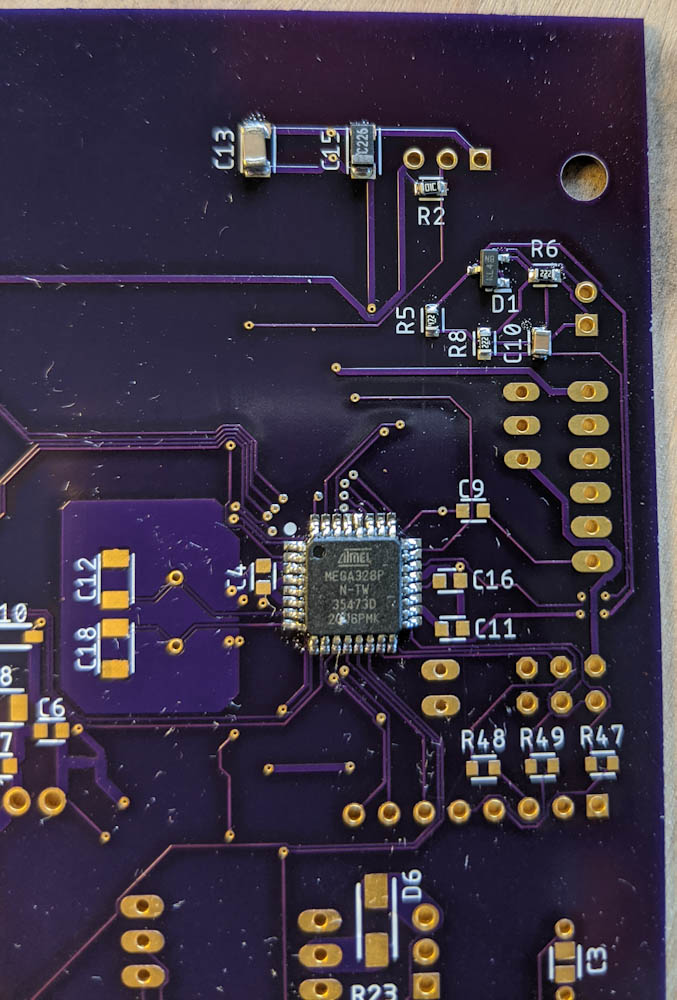
Step one was to ensure I could get the small-pin chips soldered. This is the Atmega328 and a few of the passive components.
I started with the hardest part, the Atmega328 32-pin package, since I didn’t want to do a bunch of other work and then screw that one up. My first attempt looked a bit uncertain, when I probed the pins there appeared to be an invisible bridge between two of them. To be on the safe side, I melted it off and started over.
Once I was done with the chips, there was just a loooong list of capacitors and resistors, with a few diodes and transistors in there. It took a while to make sure I got the right component values on all the places, but after a few hours it was done.

All components and connectors mounted, ready for testing.
With all the components mounted, it was time to try to flash the Atmega328 with the wireless boot loader and set the fuses accordingly. No joy. I was wondering whether I had overheated the chip when soldering, because all the connections checked out, until I noted that I had flipped a diode. With that fixed, I got the chip flashed correctly.
Then I had to program the Xbee with the correct settings to connect to my mesh network. The requirement to be able to connect both the Atmega or the Xbee to the serial line for programming took some thinking. Furthermore, the Xbee is strictly 3.3V while the Arduino TinyUSB programmer supplies 5V. This means the power to the Xbee and the Arduino needed to be isolated, as well as the serial lines.
The solution I came up with uses logic-level converter circuits. There is an ingenious bi-directional level converter circuit that uses a single FET and a few resistors. These convert between two voltage levels and will also block signals if one of the two supply voltages are zero, so by adding two of these converters between the serial ports on the Atmega and the Xbee, with a header in between, and a jumper that determines whether the header powers the Atmega or XBee, we get all the desired features: There is no back-powering between the Atmega and XBee power circuits or over the serial pins, but when powered through the onboard voltage regulator they can communicate over the serial lines.
Finally it was time to power the 12V in and see if everything worked, which it did. Almost. One of the LEDs hooked up to the XBee didn’t work, which turned out to be another flipped diode, easily fixed.
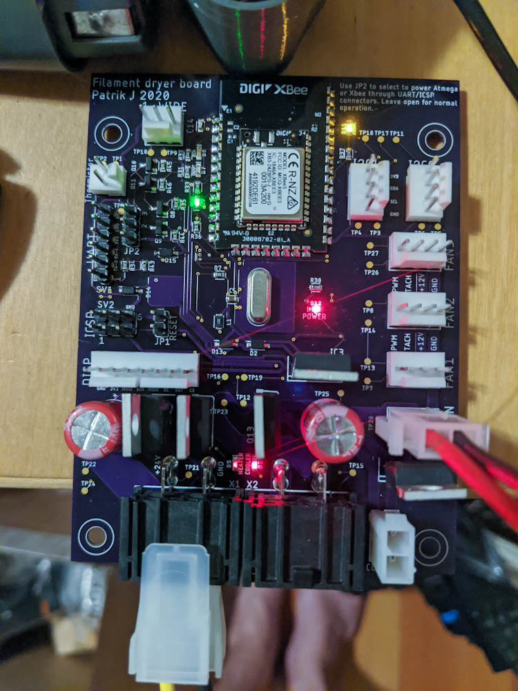
The board powered up for testing. The two red LEDs at the bottom indicate when the heater and the thermoelectric cooler are on, respectively. The red LED in the center is the 12V power indication, the yellow at the top the Xbee association light, and the green in the upper left shows the XBee RSSI (radio received power). There are two more LEDS there that show traffic on the serial send/receive lines.
Everything works so far in that the heater and cooler output LEDs blink when turned on and off, and I can talk to the board over the XBee. I haven’t attempted to hook up any of the peripherals yet, though.
Now I really need to get back to glassing so I can assemble the box and start wiring things up.