I was asked in a comment in the previous post to share the details of the antennas I made, so here we go.
The Franklin antenna was made as described here, made out of #6 gauge copper wire (which is 4.1mm diameter). However, bending 4mm copper wire in sharp angles isn’t so easy if you don’t have special equipment, so it was hard to get the bends to be in the exact right places. For this reason, my measurements are a bit off from that site (the real antenna isn’t even exactly symmetric, but I didn’t include that in the EZNEC model).
The antenna I made has radiator lengths of about 137mm (instead of 133mm) and the folded sections are 66mm long with the wires spaced 6mm apart. The length of the folded center section and the separation between the two wires there is important for impedance matching of the antenna, so I then proceeded to tweak this in EZNEC to get the lowest SWR against the 75ohm cable. This ended up being 70mm long, with the wires 10mm apart and the coaxial feed located 10mm from the end.
The antenna in the link is also shorted in the center. Mine was like that originally, but with the preamp in the coax there is a 12V DC bias between the coax center and shield, so it can’t be shorted. One could decouple the DC with a small capacitor, but when I removed the short, the impedance matching improved, so I didn’t bother.
The plots below show the results of the simulation:
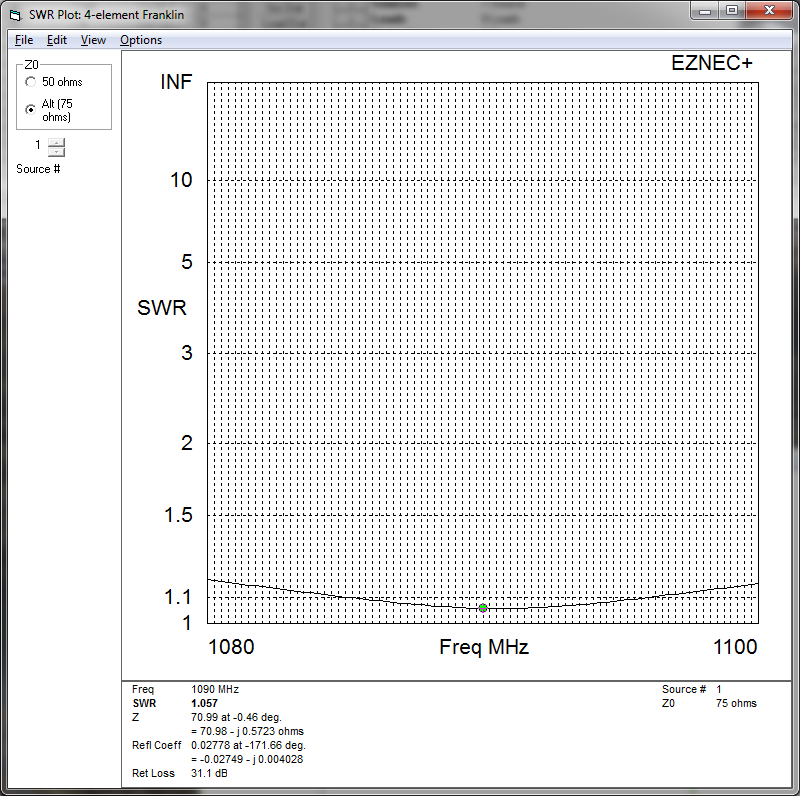
The SWR of the Franklin antenna as described. At 1090MHz, the SWR is 1.06, pretty much as good as it gets.
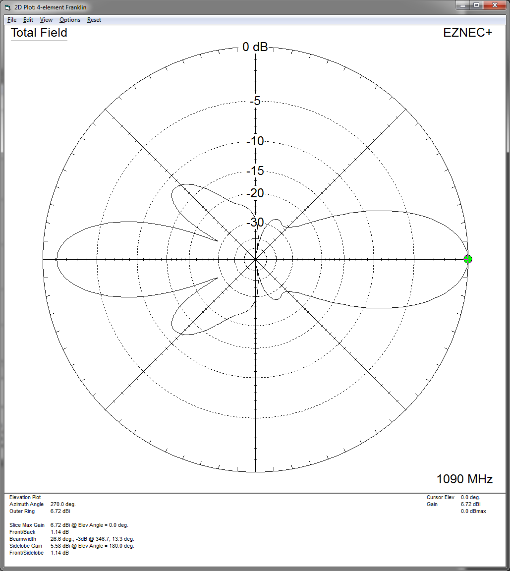
The gain vs elevation plot, with a maximum of 6.7dB. The maximum is in the direction opposite from where the folded sections point, but the front/back difference is only 1.1dB.
I don’t have any equipment to measure the SWR, but that this setup worked well is roughly confirmed by anecdotal evidence from the maximum range I could detect airplanes at (there isn’t enough traffic to get a very good idea, and most planes are concentrated into 3 routes so apart from those 3 I don’t get much data).
However, I wouldn’t overthink the antenna for detecting ADS-B broadcasts. Like I said in the previous post, I got 80% of this range with just a quarter-wave dipole of two short wires attached to the end on the coax. Getting the antenna in a spot that has free line of sight is the most important thing.
Great! Thank you for sharing your valuable work!
The dipole with each leg 1/4 wavelength is the tiniest resonant antenna, impedance 75 ohms, theoretical gain 2.1 dBi. Your 4-element Franklin’s gain is 6.7 dBi. If you compare both WITHOUT amplifier, the difference of range will be much prominent. When compared with 10 dB+ amplifier, the difference is dimmed by the AGC of amplifier, adding more dB to low gain antenna than to high gain antenna output. This is what I have practically observed when comparing tiny 1/4 wavelength legs dipole (my first ever ADS-B antenna), with Franklin & Coaxial Collinear.
This was before I added the amplifier, when I only had the antenna connected to the receiver with a 2-ft stub of coax. I interpret the results as meaning that over open line of sight (like here out over the ocean) there is plenty of signal all the way out to distances of 400+km where the planes get very near the horizon. Only at that point does the extra gain of more directional antennas make a difference. The situation may be different if you’re not looking out over the open water since the signal may then be slightly disturbed by trees or slight diffraction propagation and be weaker already at closer distances.
Put another way: looking at the 1090MHz waterfall on SDR# or something, it was clear that I could see the antenna noise already without the amplifier, because disconnecting the antenna dropped the overall noise level noticeably. At that point, the system should be antenna noise limited (as opposed to receiver limited) and adding the amp shouldn’t make much difference except allowing you to overcome the loss in a longer coax.
I agree with you. Thanks for the detailed explanation.