In the previous spindle post, I talked about replacing the bearings, how I was not very happy with how that had worked out, and how I had ordered angular contact bearings to replace the deep groove ball bearings. Now it was time to do it.
While searching the web for writings about these spindle bearings, I came across the “Benchtop Machine Shop” blog, which has several posts about replacing the spindle bearings in his mini mill with angular contact bearings. Their mill is not exactly the same model as mine, as it has an MT3 spindle, so his bearings are different (his mill has two 7206 bearings while the HiTorque has a 7007 for the lower bearing, because the spindle is 35mm dia at the bottom instead of 30mm) but the procedure and concerns are the same.
They also noted that the standard bearing replacement instructions have you pressing the bearings through the balls, and also damaged a set of bearings that way. They also thought a lot about how to preload the bearings. The procedure they used was to take down the diameter of the seat for the upper bearing enough that it would only be a light press-fit such that the preload could then be set with the nut. This made sense to me, so what I’ll describe below largely follows the same procedure.
The first thing I did was to order a completely new spindle from LittleMachineShop. The old one was worn in the taper and the hole for the spindle lock was rounded, so I figured if I’m going to do this I’ll replace the spindle while I’m at it, since it’s not very expensive.
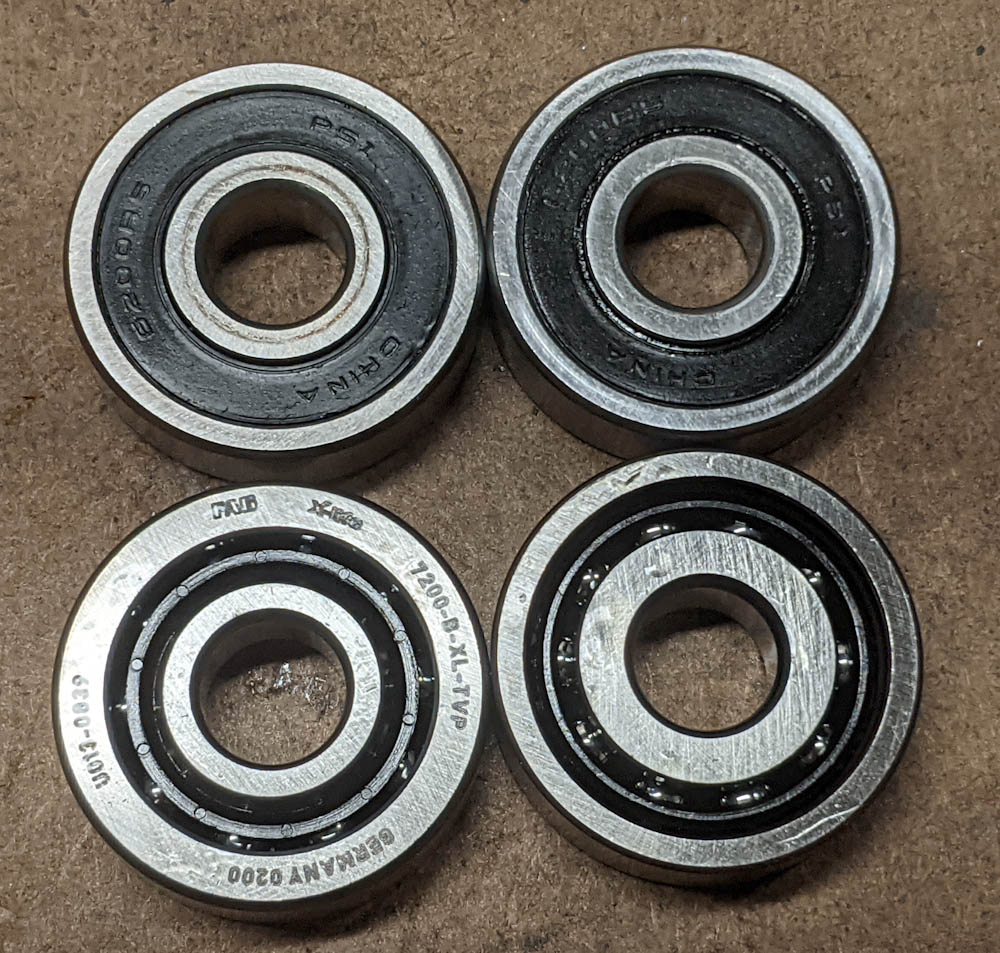
Sealed angular-contact bearings are much more expensive than open ones, so I decided to try using open ones. (Sealed bearings also have lower RPM limits since the friction in the seal heats them up.) If the replacement works but they end up getting contaminated or flinging grease everywhere I can upgrade again.
For the upper bearing, SKF has an angular contact bearing 7206BECBP that has the correct inner and outer diameters but is 16mm wide rather than 14. This is not a problem because the seat for the upper bearing is actually a bit wider than needed for the normal bearings, and I could get it on Amazon for $26.
The lower bearing is a bit more uncommon. SKF only has 7007B size bearings in the “super precision” category at many hundreds of $$$, and that seemed to be the norm for other brands as well. (The “B” means it has a 40-degree contact angle, which is what we want in this application since we will have a large preload. I think “A” is 25 degrees and no letter at all is 15 degrees, which would not be optimal in this application. I did find a “VXB” brand 7007B bearing for $25. I’m not clear on exactly what the quality of these bearings are, but they at least have an American website. They don’t state what the ABEC grade of the bearing is or anything, but I figured it was worth a try.
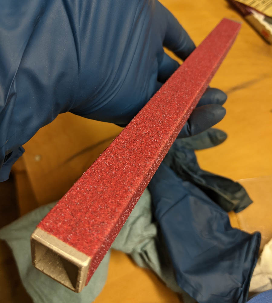
Step one was to carefully sand the upper bearing seat down until its diameter was appropriate for a “transition fit”, which as far as I could decipher the SKF tables was a diameter of 1.1811″-1.1807″. (I dunno why they give diameters in inches for metric bearings, I must have found the table they give to Americans…) The spindle as delivered was 1.1812″ (this gave me an occasion to add a 25-50mm digital micrometer to my metrology stable) but after sanding with strips of 400-grit wet or dry while rotating the spindle, I got it down to 1.1806″-1.1808″ (it appeared to be slightly conical but that’s probably what you get when you try to accomplish tolerances of 10um by hand.) For reference, this is 29.987 – 29.992mm. I don’t have an inside micrometer, so I couldn’t measure the actual diameter of the bearing, but I figured this would be good.
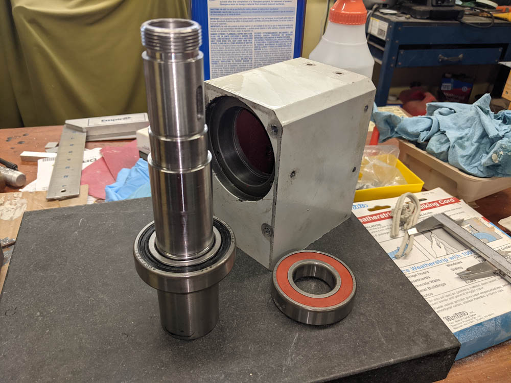
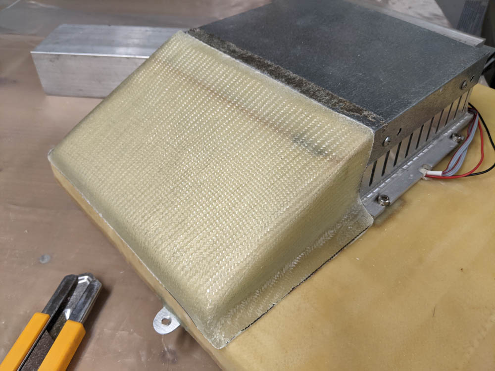
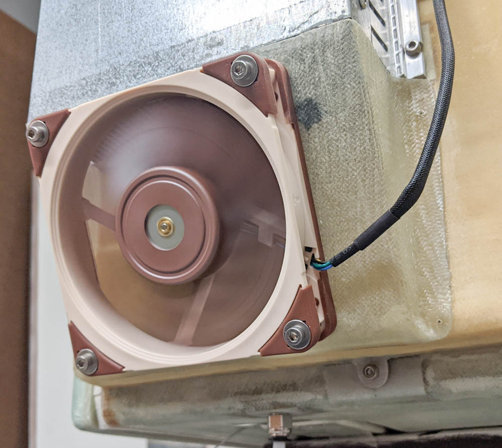
Step two was to get the lower bearing onto the spindle. Rather than pressing it on, I followed the example I linked to above and accomplished this by temperature differential. After keeping the spindle in the freezer for a few hours, and the bearing in the filament drying box while it was heating to 80C (it’s quite convenient to have a little “workshop oven”…) the bearing dropped right into place.
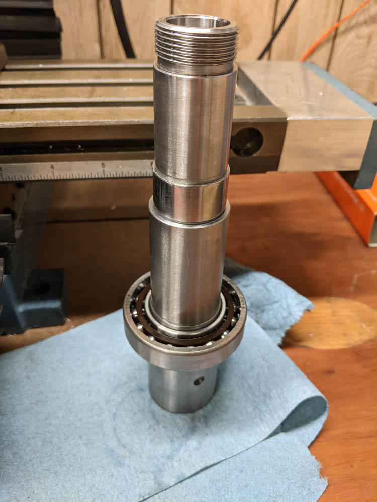
The lower bearing was mounted by putting the spindle in the freezer and heating the bearing to 80C, at which point it just dropped in place.
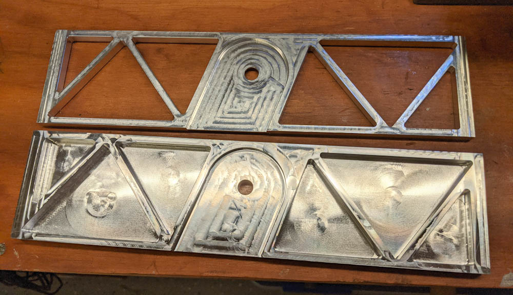
Step three was pressing the upper bearing into its seat in the mill head. While I had the mill together I had made sure to fabricate two collars that would fit over the bearings so they wouldn’t be side loaded in the process.
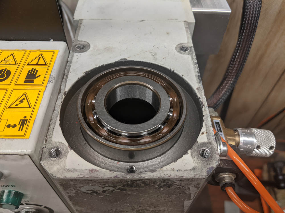
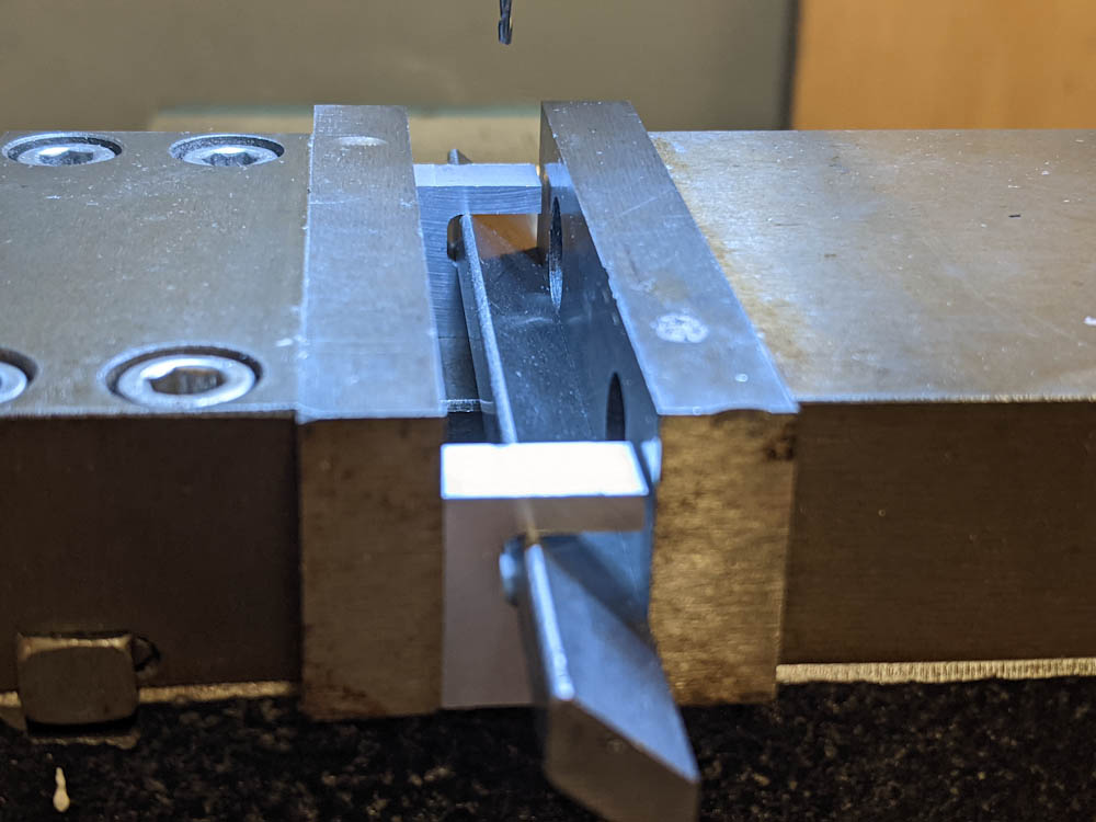
Here the upper bearing has been placed in position, ready for pressing in.
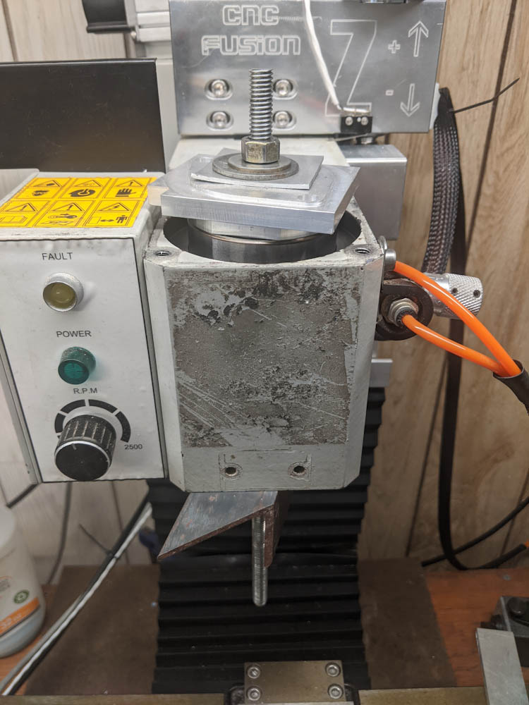
The upper bearing being pressed into place. Note the round aluminum collar fitting over the bearing, and then a random square part used as a space.
Pressing the bearing in worked pretty well. It did initially get cocked so I had to gently tap it on the side to get it to realign itself. After that, it slid right into place.
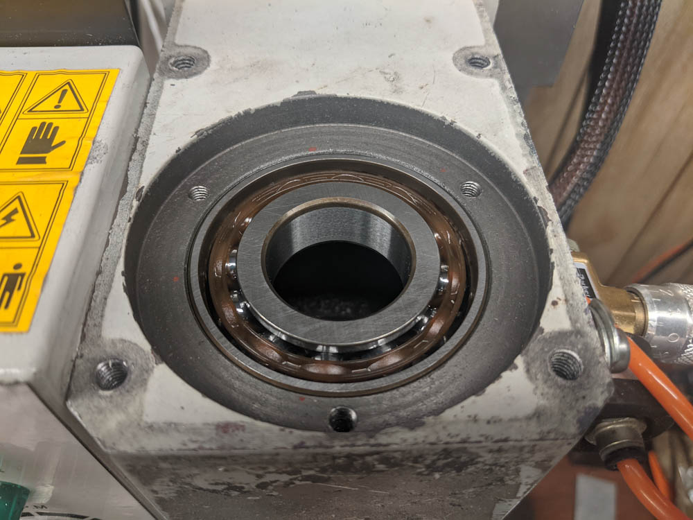
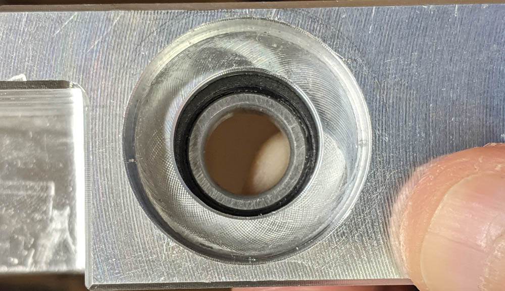
Upper bearing pressed into place. Note that even though this is 2mm wider than the original bearing, it does not protrude above the seat.
Angular contact bearings must be mounted in the right direction. Obviously, since they can only take loads in one direction, the two bearings must be opposite. But that still leaves you with two choices. In this case, since we want to use the spindle nut to preload the bearings, the inner races will be preloaded towards each other. This means the wide part of the inner race must face outwards on both sides.
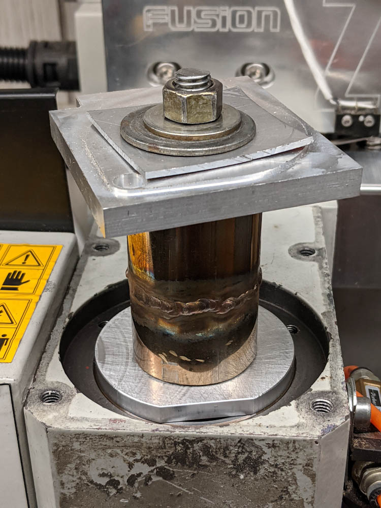
After getting the upper bearing into place, it was time for the the final step four: pressing the spindle and the lower bearing into place. By using the collars on both sides, there was no side loading on the bearings.
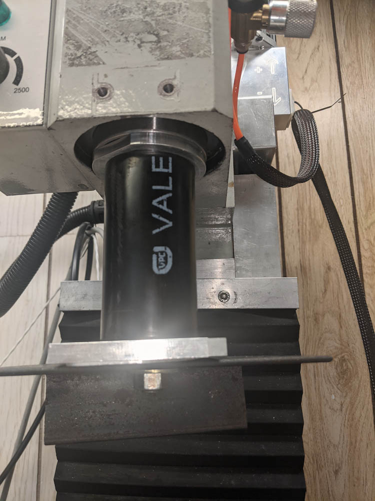
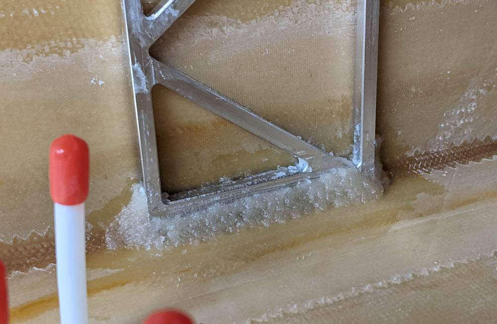
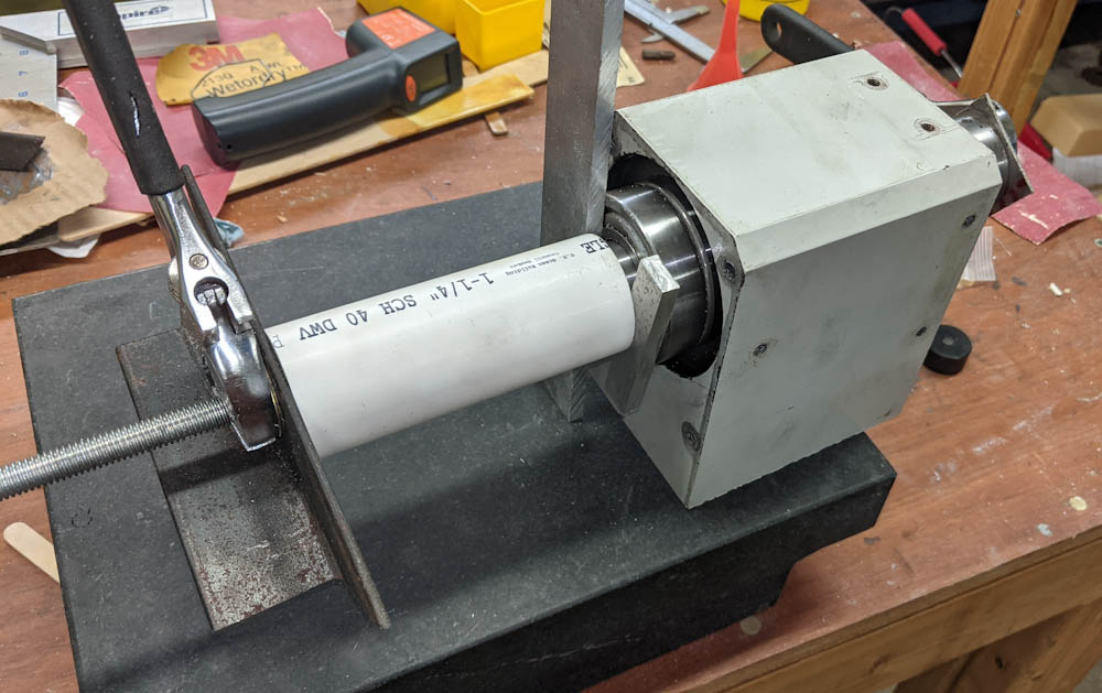
The bottom part of the setup for the final operation. The lower bearing is positioned on its seat, with the collar, a plastic pipe spacer, and the angle against which the nut is tightened.
On top, we have the collar that ensures the bearing is not side loaded, a spacer for the top of the spindle, and then another random part so the nut can bear on the spacer.
The threaded rod used is 3/8″ and I think it would be better to have a larger one, because it’s springy enough that when you tighten the nuts the bearing doesn’t move until you’ve preloaded the rod so much that the bearing then “jumps” once it’s started moving. This isn’t such a big deal if you’re pressing it tight against a stop, but in this case the upper bearing will be “free” on the shaft and we don’t want it to jump such that it preloads itself. The collar should prevent this from happening, but it felt a bit iffy. With a stiffer setup (1/2″ or maybe even a 5/8″ rod), it would probably move a bit more predictably as you tighten it.
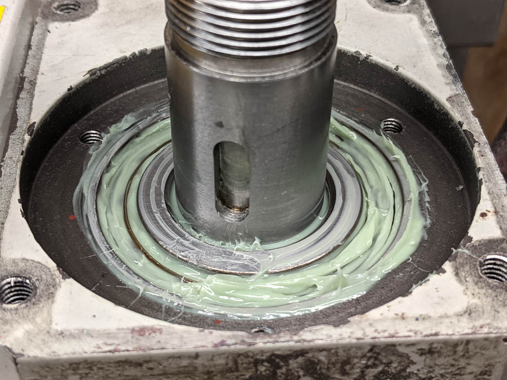
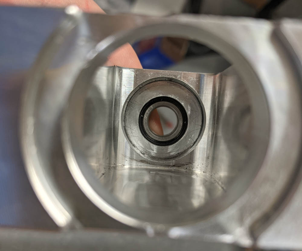
Spindle is in place, the bearing has been greased, and the pulley for the belt is ready to mount.
Once the bearings were in place, there was about 0.2mm radial and 0.15mm axial play at the bottom of the spindle, so at least I had successfully avoided preloading the bearings while pressing them in. Now I just needed to figure out how to set the preload.
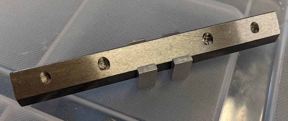
I took an idea from the benchtop machine shop, who cut down a 32mm socket to make a tool with four tangs that could be used to tighten the spindle nut. This took some Dremel work but worked great. I could now tighten the nut with a torque wrench rather than the “C-spanner” that came with the mill.
The remaining problem, though, was how to hold the spindle while tightening the nut. The spindle is obviously round, with only a little hole for the pin used with the spindle lock. This is not very secure and it’s hard to hand-hold the spindle while tightening the nut, too. I wanted a more stable way to hold it.
My first idea was to use the drill chuck to hold a hexagonal Allen socket. I could then put a ratchet handle on the socket and hold the spindle that way. This worked initially, and I managed to take most of the free play out of the bearings this way. Once I needed a bit more torque, however, the drill check spun on its taper.
The setup for tightening the spindle nut. The drill chuck is holding a hex socket with a ratchet handle. On top, the custom-made nut holder socket is used with a torque wrench.
Despite trying a few times, I could not get the drill check tight enough on the taper to hold. My next idea was to mount a large hex socket directly in the 3/4″ R8 collet. The collet can not spin on the spindle because of the locating pin, and I figured with only the hex edges biting into the collet it would not spin either. This turned out to be correct, but I was concerned it would ruin the collet. I don’t really ever use this 3/4″ collet so that wasn’t really a problem.
Using this setup I got the final free play out of the bearings. There was no longer any detectable motion either axially or radially. There was a noticeable amount of friction in the spindle, but most seemed to be because of the grease because when reversing direction there was a short distance with much less friction. And in any case, when measuring the torque needed to turn the spindle by wrapping a string around it and pulling, it took about 1/7 of what it did with the old bearings.
The old bearings required 0.7kg weight as read on a spring scale used to pull the string around the 40mm diameter lower end of the spindle. This works out to 0.7kg*9.82m/s^2*0.02m = 0.14Nm torque. Converted to american units, this is 1.2in*lbf. The Benchtop Machine Shop measured 1.0 on his bearings, so this seemed pretty close. They guessed that a range of 0.6-1.5 was acceptable, although I don’t know what they based that guess on.
With the angular contact bearings, the spring force needed was 0.1kg, which would be far below the range above. This might indicate I need more preload, but since there was no play I decided to run the spindle and see what happened.
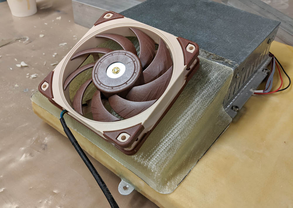
Initial results were mixed, it made what I can only describe as a “gurgling” sound, presumably this was from the grease being moved around. Gradually upping the speed to the full 5000RPM and measuring the temperature using an IR camera, the temperature rose steadily until it peaked at 67C.

IR camera image of the mill head. The temperature peaked at 67C and started coming down.
The sound gradually changed to become less noisy, but every now and then you could hear the spindle bog down a bit. I assume this was blobs of grease being sucked back into the balls. After peaking, the temperature started slowly coming down. This is textbook behavior for new greased bearings, as the grease gets distributed the friction decreases and the temperature comes down from an initial peak.
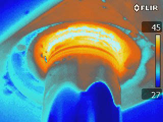
Infrared view of the lower bearing. The metal parts have low emissivity, so look “cold”, but they’re really pretty much the same temperature as the grease in the bearing.
While doing this I periodically stopped the spindle to measure friction and make sure there was no free play. Remember that the preload will have a tendency to decrease as the spindle heats up and moves the inner races further away from each other. This appeared to not be a significant effect, maybe the friction is low enough that the spindle and housing have about the same temperature so there’s little differential expansion.
Once this “run-in” had completed, I measured the torque required to spin the spindle (while at operating temperature). Initially the force needed seemed to be more like 0.05kg, gradually increasing towards 0.1kg. It’s hard to measure with the equipment I have, but it would be expected that the friction would increase if the spindle itself is first hotter than the housing but then as it’s stopped the temperature equilibrates and the preload goes up.
I also attempted to measure the stiffness of the spindle, that is, how much it deflects under load. Using the dial test indicator near the lower bearing and a luggage scale wrapped around the spindle, It seemed to require about 20kg of sideways force to deflect the spindle 0.01mm relative to the head. If we assume this is deflection in the bearings and not in the spindle or mill head, it works out to 22N/um. At some point I found a table by SKF of bearing stiffness as a function of preload, but I can’t find it now. As far as I remember, the numbers were more like 100-300N/um, so this seems to either mean that the bearings aren’t sufficiently preloaded or that something else is flexing.
Unfortunately I never measured the stiffness of the original bearings. It would have been nice to have a reference. Given that the friction in the spindle is so low, I could probably attempt to up the preload a little bit, but I don’t have a lot of confidence in my ability to accurately turn the nut by small amounts. (The nut has an annoyingly coarse pitch thread. Given that it’s the thing that sets the preload, it would have been nice if the thread was as fine as possible…) On the flip side, I decided to try some cuts and it seems to work well, so maybe I shouldn’t “chance um”. If I turn the preload up too high, I’m not sure that backing the nut off will help, since the bearing is still quite tight on the shaft.
Anyway, this was a very long post but I figured it would be nice to describe this is some detail given that I had such a hard time finding anything about it. I’ll post an update once I’ve had some experience with how it runs with these new bearings.