With the sides of the box completed, it was time to glass the top.
The layup itself was pretty straightforward, since it’s just a flat piece of glass that laps onto the sides and back. I added aluminum hardpoints for the screws that will hold the electronics enclosure and another hardpoint that can be used to make some sort of clip for the condenser cover, I haven’t worked that part out yet.
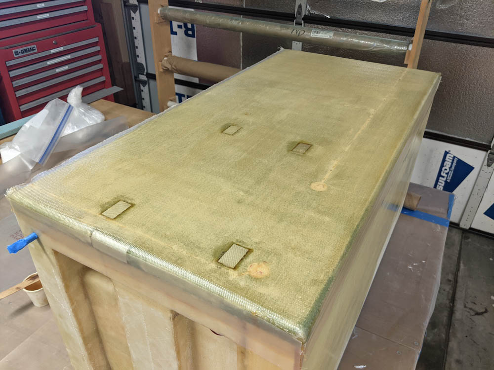
The top surface of the box with the layup done.
The only hard part about these larger layups is that I’m suffering from having too small epoxy cups. For smaller work, my 2.5oz paper cups are pretty good, but when making these larger ones, I have to run over to the hotbox and mix more constantly. I should really get some larger cups, too. (Imagine laying up an entire wing skin using 2.5oz cups. It would take days…) As usual, peel ply was added where the glass laps onto the sides, ensuring a smooth transition.
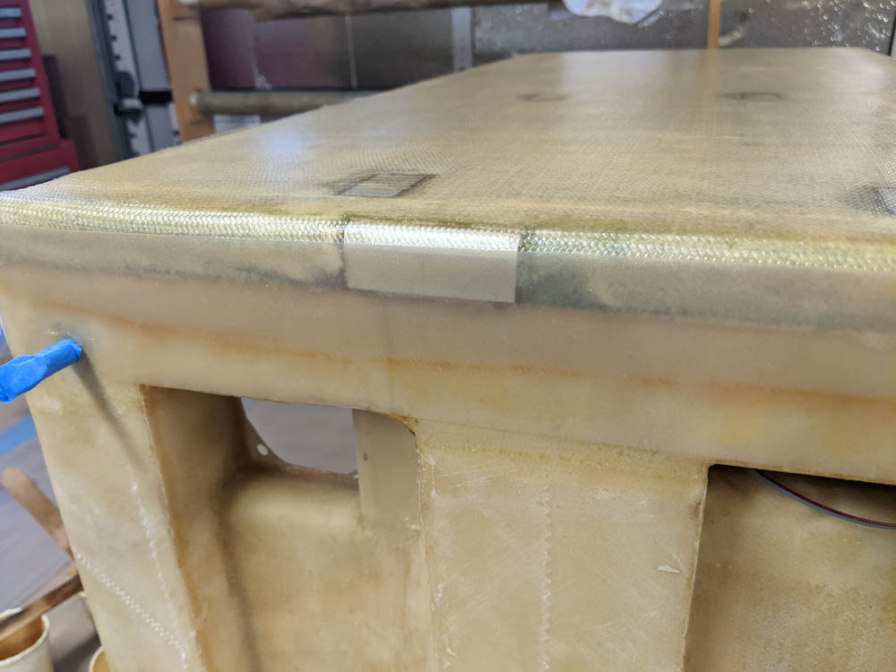
I put in a hardpoint that can be used to hold the right side cover. Not sure exactly how yet, but it’s there if needed.
As an aside, I got new peel ply tapes from Aircraft Spruce. There are two types of these tapes, with smooth or “pinked” edges. “Pinked” means it’s cut in a zig-zag pattern. When I initially ordered the composite supplies back in 2013, I got a roll of “pinked” 2″ tape, and that turns out to be the wrong choice for fiberglass work. The zig-zag pattern leads to lots of little strands getting stuck in the corners. Apparently, when you do fabric covering of tube-and-rag airplanes, you want pinked edges, because it attaches better when you join fabric together. When using it on top of layups, though, that’s exactly what you don’t want. These new tapes, with straight edges, work way better.
Once the epoxy had cured, it was time to attempt to cut out those wire holes. If you remember from earlier, they had been covered with sealant to prevent the epoxy from getting into the holes. That had also covered the 3-conductor wires for the temperature probes that were now enclosed under the glass.
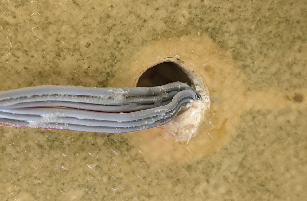
Using a fresh X-Acto blade, I started cutting the glass, trying my best to not cut into the wires. This turned out to be pretty difficult, and before I had gotten the holes cleaned out, two of the three wires had substantial cuts into the top conductor. I checked the probes and they still work, but this was not a good way of doing this. At the very least, I should have added some heat shrink tubing to the wires as they exited into the hole to give them more resistance to errant cuts.
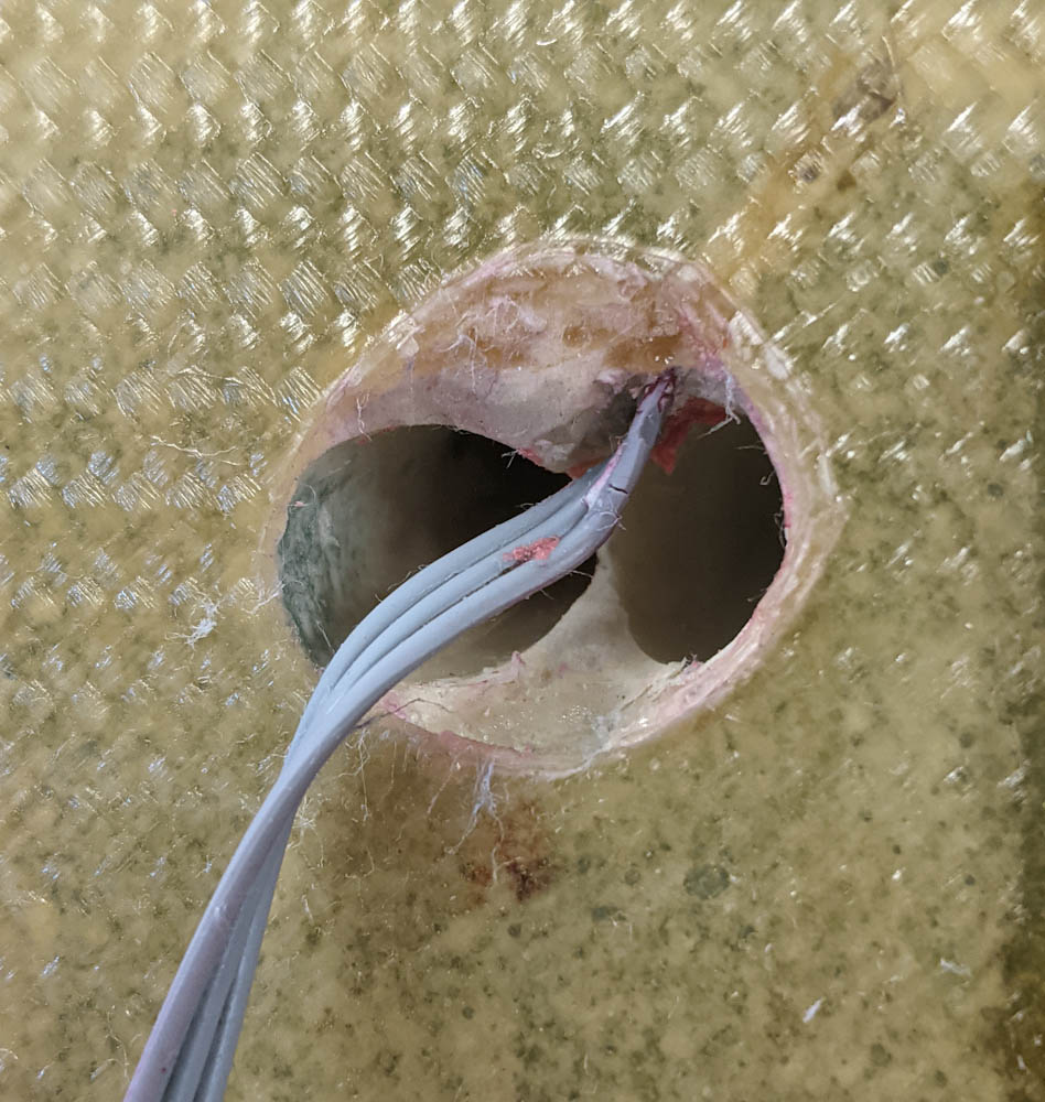
The wire hole cleaned up. The damage to the insulation of the temperature probe wire is clearly visible.
The other hole has two wires coming out of it. Here, too, I managed to cut into the insulation of the top wire.
The hole that had two wires also had had some epoxy run into it. The sealant must not have covered the entire area, or the epoxy entered from the wire trough between the two wires. It wasn’t too bad, the cured epoxy mostly peeled off the wires pretty easily.
With the wires extracted, I drilled and tapped the holes for the electronics enclosure, which completes the top of the box.
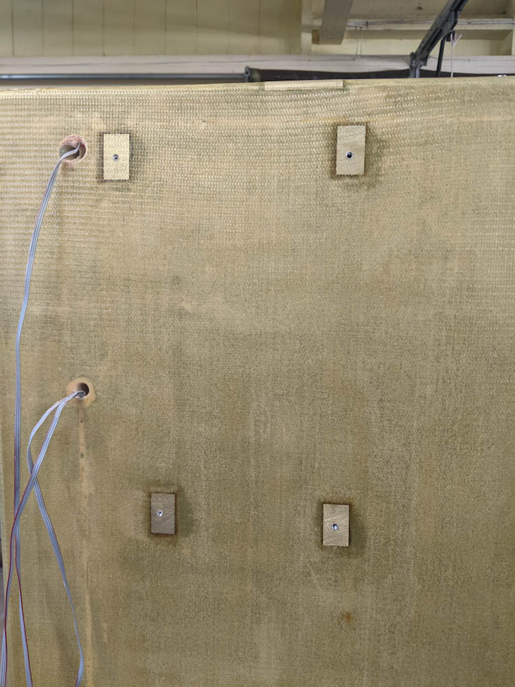
The four hardpoints for the enclosure have been drilled and tapped.
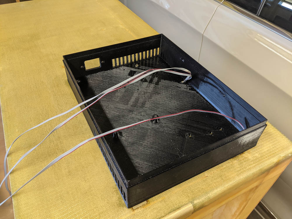
The bottom of the electronics enclosure temporarily screwed in place to test the fit.
Now I can’t put off finishing the bottom any more, so I have to make a decision on what to do with the filament exits. I also have to add a drain hole where the condensed water from the dehumidifier can exit. Here I’ll use the same kind of tube I used for the storage tubes.