The last time the CNC mill got some love was when the steppers were replaced with servos. This was quite a while ago, and the mill hasn’t seen very much use since. However, it was now time to machine the holders for the filament rolls for the storage box so I got started squaring the stock. Then several things went wrong.
First, I noted that the motion controller was losing position under certain conditions. After reporting this on the g2core github page, it became clear that this was a regression and there was a workaround. I was pretty unhappy about this, since this is what a motion controller should absolutely never do.
As a consequence of losing position, I then ran the mill head into the hardstop. This wasn’t the first time, but after this, the z-axis ballscrew started sounding even worse than it usually did. It was bad enough that I considered it unacceptable, and decided it was time to do some servicing on the spindle.
First: clean the ballscrew/ball nut. I wipe the screw with oil every day I use it, but it’s never been cleaned since they were first mounted, since this requires removing the head. While it is shielded from direct debris coming from the spindle, the z-axis ball screw is in the open and small chips will find their way there and stick on the oiled surface. These then get ingested in the ball nut and you get binding.
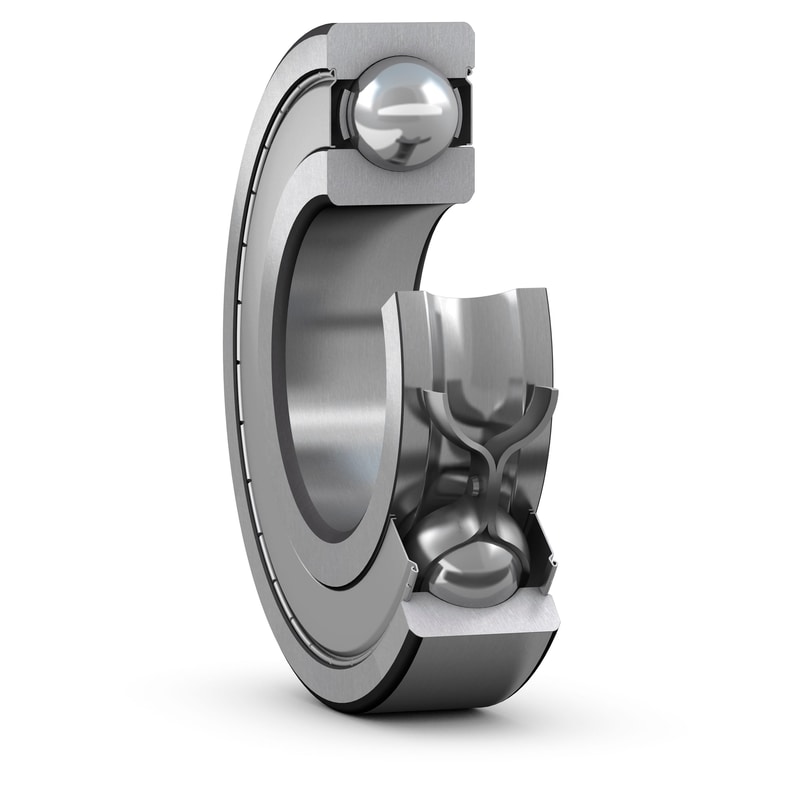
Second, as I took the ballscrew off, I realized that its thrust bearings were in bad shape. They felt very “gritty” as they were turned. These are deep-groove radial ball bearings and the axial loads from the mounting preload and accelerating the heavy mill head up and down are probably higher that what they’re designed for. In any case, they needed replacing. No big deal, they’re cheap (we’ll see if the new ones are better quality…)
Third, I’ve had a kit I got to upgrade the spindle from 2500rpm to 5000rpm for years. Since the spindle is belt driven, this is easy, just change the gearing in the pulleys. However, LittleMachineShop.com also supplied two new spindle bearings since they said the no-name chinese bearings in the spindle can’t handle 5000rpm. I haven’t felt confident about being able to press out the old bearings and, more importantly, in the new ones, since I don’t have a hydraulic press. However, after having gone through the exercise of replacing the swingarm bearings on the NC30 last year (apparently I didn’t post anything about that), I felt a lot more confident about my ability to muddle my way into replacing the bearings!
After having remove the head and taken the ballscrew off, I embarked on the cleaning journey. I started by spraying mineral spirits through the ball nut and running the screw up and down repeatedly. I did this over a bucket and soon there was a bath of mineral spirits with tiny shiny flecks floating around. Clearly something was coming out. The ballscrew would still bind, though, so eventually I overcame my fear of dismantling it, read up about how to service ball nuts, and took it apart.
It’s a very ingenious device. Inside are 70 small (1/8″, 3.2mm) balls which roll between the screw and the nut, kind of like a ball bearing cut up and twisted into a spiral. But then you need a way for the balls to return, so at the end of the ball nut is a small tube that picks up the balls coming out and routes them back to the beginning. All you need to do is take this tube off and turn the screw and all the balls will pop out, one after another, until the ball nut is free.
I managed to not lose any balls, swirled them in mineral spirits; flushed and wiped the track in the ball nut, and did the same with the entire screw, and reassembled it. Success! It now ran smooth as butter all the way from one end to another.
Then it was time for the spindle. I found a related instruction about how to change bearings in the “SX2” mill that the HiTorque mill I have descended from. The spindle isn’t exactly the same, but close enough for the instructions to be useful.
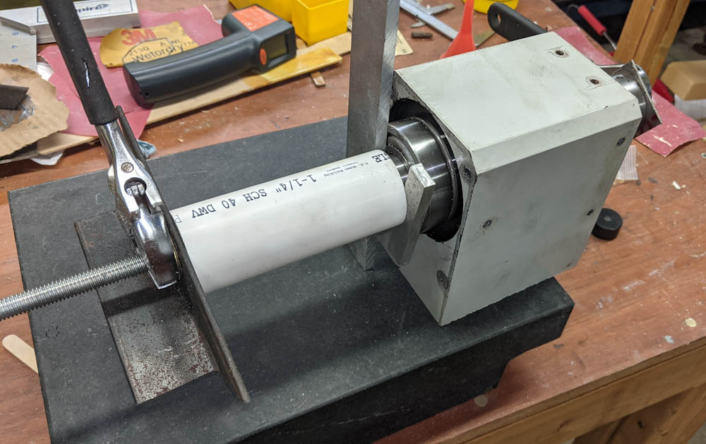
In lieu of a press, the bearings can be pulled off and back on using a threaded rod through the spindle center and some collars so you can bear on the bearing races. The collars can be made from plastic PVC pipes. Getting the bearings off was not a big deal, but it’s easier when you don’t have to worry about damaging them.
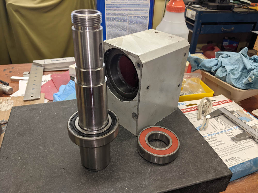
Now for the new bearings. These are higher quality (SKF and Nachi) sealed deep groove ball bearings. The lower bearing is pressed onto the spindle shaft first, then the upper one is simultaneously pressed onto the shaft as the two outer races are pressed into the housing. This felt more iffy, since you shouldn’t side load the bearings. Had I been better prepared for this, I would have fabricated some collars of the right size to fit against both races of the bearings, but as it was, I had to improvise.
One thing you always have that’s the right size is the old bearing. This works as a collar on the side where the new bearing is going in, but not for the old one since there’s a shoulder. I ended up having to press it by its inner race only, which might have damaged it. I did eventually get them into position.
However, the spindle was now very hard to turn. It’s not hard to understand that pressing in this way will preload the bearings axially. Now, some preload is good, because for stiffness you want all the play in the bearings taken up so it can’t move around. Too much preload, however, is bad, as it overloads the bearing, creating too much friction. I attempted to run the spindle like this, but it became very hot, very quickly.
Another consideration is thermal expansion. The preload specification I found for the SKF bearing called for “heavy preload” being around 10um (0.01mm) axial displacement of the race. Disregarding how you’re supposed to control the position to that accuracy given that you’re just pressing the bearing into the housing until it won’t go any further, 10um is also about the expansion of the spindle with every 10C temperature increase. The cast iron housing also heats up, but not nearly to the degree that the spindle does (after running a long job with the old bearings, you could not keep your hand on the spindle without it being painful, while the housing was merely quite warm.
So what does this mean? As far as I can tell, the typical way this is handled is by having one bearing slip fit onto the shaft, and then controlling the preload with a spring washer. As the shaft heats up and expands, the bearing can move and the washer will keep the specified preload. That’s in conflict with the desire to have all surfaces press-fit to maximize rigidity in the case of a machine spindle. What it appears you have to do is arrange the bearings such that the preload is correct at operating temperature, and such that preload goes down as temperature goes up. This means that there will be a lot of friction when the spindle is cold, but as that friction heats it up, the preload, and friction, will go down, thus creating a negative feedback.
What you don’t want to have is a situation where the preload goes up with temperature, since that would mean as the spindle heats up, friction goes up, which makes it heat up more. A positive feedback, which could lead to overheating. The spindle motor is 500W and if you end up turning all that into heat in the bearings, they won’t last very long (and you won’t have any power left to cut metal with, either.)
Anyway, after fiddling with pressing the bearings slightly back out and trying a couple of times, I ended up with a reasonable preload where the spindle is not too hard to turn and does not get harder to turn as it heats up, at least not significantly. The price for that success was that I damaged the shield on one of them, so it was rubbing and I had to rip it off entirely. So now I have an unshielded bearing. I don’t think this is a big deal, there is a cover plate over the bearing and I 3d-printed a new one that leaves very little clearance to the spindle. It seems very unlikely chips will get in there. More likely, the grease will seep out of the bearing. But from what I could conclude from SKF’s documentation, an open bearing on a vertical shaft at these sizes and speeds will need to be relubricated only every 250 hours. Given how much use the mill sees, that seems like an acceptable tradeoff for having a 5000 rpm spindle.
From what I can conclude, though, this is not an application where deep groove radial ball bearings are a good fit. There is too much axial preload. What higher quality spindles seem to use are angular contact ball bearings, which are ball bearings where the races are tilted about 45 degrees. This gives them excellent ability to handle both radial and axial load, but only in one direction. That’s fine, since you always use them in pairs anyway. They also have less friction for a given preload.
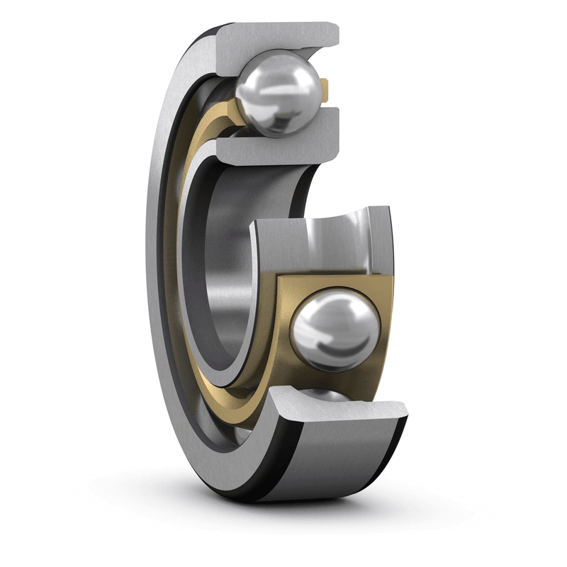
Being able to only take axial loads in one dimension is actually a plus in this context, too, because you can unambiguously know which direction will give higher preload. This means that not only is it clear how to mount them to ensure preload goes down as temperature goes up, you also always know in which direction to move the bearing to get more preload.
Sealed angular contact bearings are quite expensive (like $100+) but open bearings are about the same price as the deep groove ones I use now. Given that I’ve likely damaged at least one of the bearings, I’m going to try replacing them with angular contact bearings and see how that works out.
In any case, I’ve learned more than I ever knew about ball bearings from this exercise. As the homebuilt aircraft community say, it’s all done for “recreation and education”!
Pingback: CNC mill upgrade: Z-axis – Patrik's projects
Pingback: CNC mill upgrade: Spindle part 2 – Patrik's projects
Pingback: Filament storage part 20 – Patrik's projects