In the previous post I talked about how the mount for the X-axis stepper motor in the CNCFusion kit didn’t line up the motor with the ballscrew axis. I realized that the clearest way of showing this was to bolt the motor mount directly to the thrust bearing mount. Any misalignment should then be obvious.
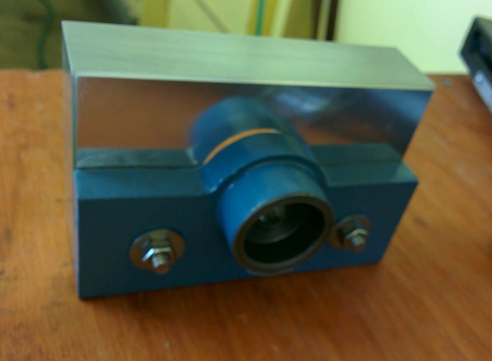
This is the blue thrust bearing plate screwed directly onto the aluminum stepper motor mounting plate. Apologies for the out of focus picture.
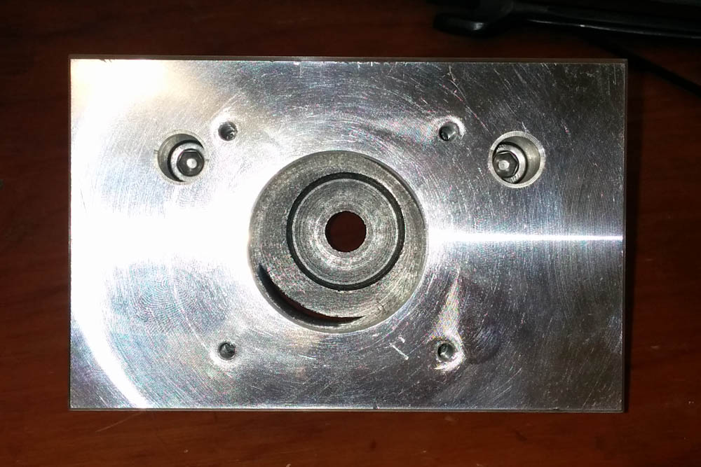
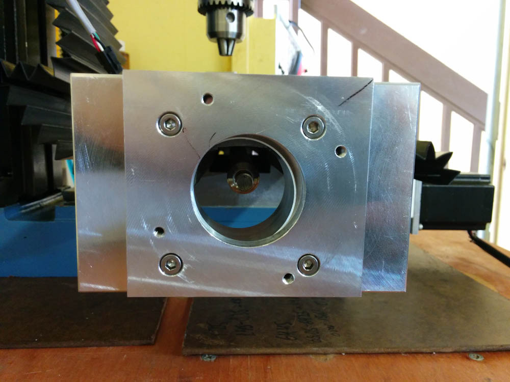
This is the view from the opposite end, down the ballscrew axis. It’s obvious that the location of the thrust bearing in the back is not concentric with the stepper motor cutout in the front piece.
As is obvious from the above view, there is a considerable misalignment. The CNCFusion plate mounts the motor too far to the back (left in the picture) and too far down. By measuring the location of the ballscrew axis relative to the bolt holes in the two pieces, I ended up with a mismatch of 2.6mm horizontally and 1.8mm vertically. Machining a new mount from scratch would be a big deal, it’s made out of a large chunk of solid aluminum. Instead, I designed a plate that would bolt onto the CNCFusion plate and move the motor the required amount. (Luckily the ballscrew is long enough that moving the motor back by up to ~10mm isn’t a problem, in the normal position both the motor shaft and the ballscrew are mounted very far into the coupler.)
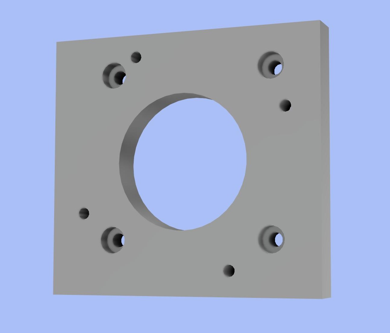
This is the motor adapter plate design in Fusion360. The countersunk screws bolt into the holes for the motor in the original plate. The rotated set of holes, concentric with the machined hole, are threaded and for holding the motor in its new position. To avoid interference between the sets of holes, the new holes are rotated by 20 degrees.
So, the first real machining project would be this plate. It’s made out of 3/8″ aluminum, and nothing too advanced. The external dimensions don’t really matter, so I faced the bar stock and squared the sides “manually” by typing G-code. Then I could clamp the piece and do all the holes in one shot, so there wouldn’t be any mismatch in their locations.
It all went pretty well, although it was a learning experience. I had to rerun the code for the countersunk holes a second time because the first time didn’t go well. First, I had designed them too small. Second, the 1/8″ endmill I used the first time didn’t sound good, so the second time I used a 3/16″ one instead. It’s possible I just pushed it too hard.
Drilling the holes was also an interesting experience. When you program the drill cycles, you have to specify how fast the mill should lower the drill. When you drill manually, you just sort of add a certain amount of pressure and the drill goes as fast as it wants, and I didn’t really have any reference for how fast to make the move. I think I made it too fast, because I ended up pushing the drill bit into the chuck, so the holes gradually became shallower and shallower. I had to manually drill them out at the end.
But the end result was a very usable piece. I made a short video of the process:
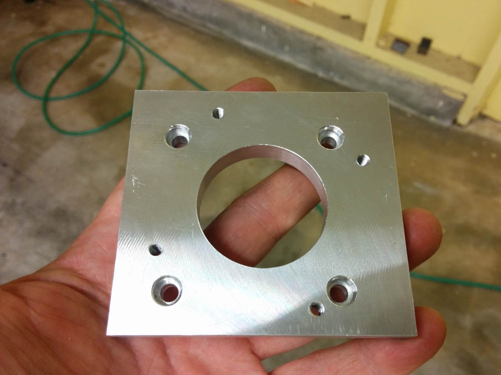
This is the finished product. It actually looks like the design!
Apart from finishing up drilling the holes and tapping the holes for the four screws holding the motor, I also had to enlarge the large hole for the motor flange a bit. I’m still a novice at this, so when I looked up the dimensions of a NEMA23 stepper motor, I input the size of the motor flange. Of course, the hole needs to be a bit larger than this for the pieces to fit together without interference, but I didn’t think of this. After a little sanding, though, the motor slipped into place.
The adapter plate mounted on the X-axis. It’s hard to see in the picture, but the motor mount is now much more concentric with the ball screw.
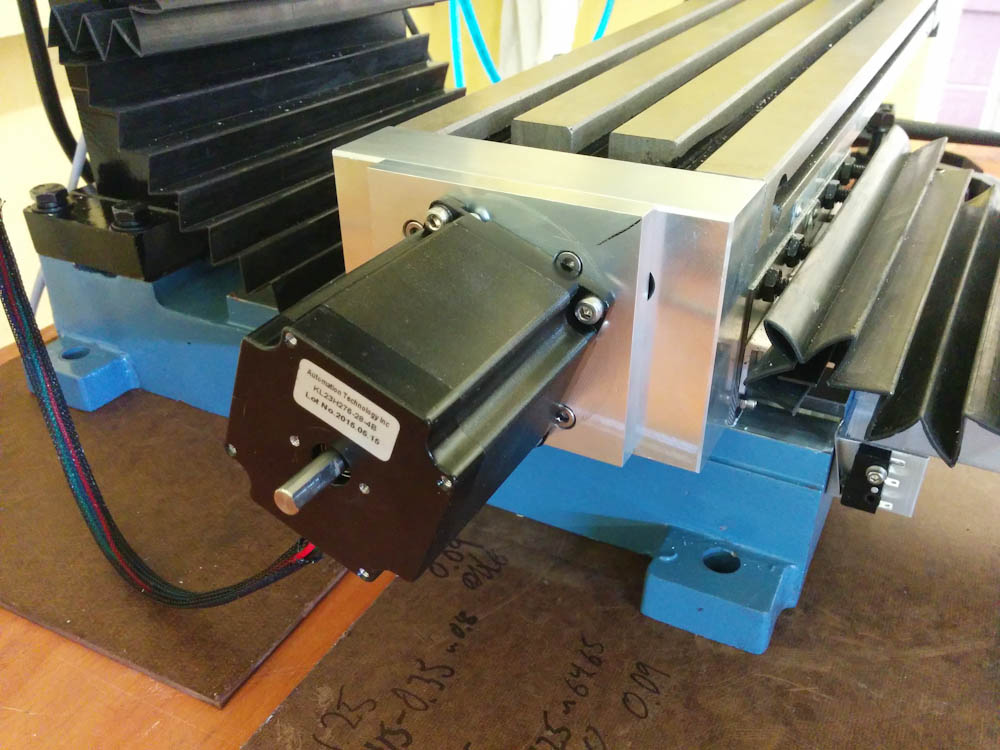
The motor mounted on the new plate. Unlike before, the motor shaft now slipped right on the coupler and the flange slid into the hole, indicating that there’s now very little side force.
With the motor mounted on the new plate, I could slide it right onto the coupling. I then loosened the thrust bearing and re-tightened it, so the ballscrew was aligned with the line from thrust bearing to motor. Unlike before however, I could now spin the ballscrew without getting any wobble in the ball nut.
After readjusting the gibs and tightening the ballnut down to the table, I can now run the X-axis back and forth without feeling any binding at all. I think this fix was a success!
(I still haven’t heard back from CNCFusion about whether they agree this is a mistake in their kit.)
Great solution! I am going through a lot of the same things you are on my CNC conversion. I have been YouTubing the process. Check out Part 4 Problems with the X, what I ran into as my primary issue was the thrust bearing washers. I’m going to take another look at the motor mount though. Good stuff.
https://www.youtube.com/channel/UC564D7x_yFfBjQRrflN00Jg
Pingback: CNC mill upgrade: Z-axis – Patrik's projects