The previous post ended with test running the upgraded spindle bearings. This testing dragged on a bit because I found the bearings loosened up. I would run up the spindle to temperature, take a few cuts, and it would start making a horrible racket. Upon inspection, it turned out there was free play in the bearings. Since I marked the nut, I knew it had not backed off, so the only possibility was that one of the bearings were not fully seated.
This happened several times, so eventually I decided to tighten the nut not just until there was no free play but until the turning torque went up. It turned significantly, so hopefully that took out whatever play there was. I then backed out the nut and just snugged it up. This should give the bearings a chance to back off the preload a bit.
I also realized that a much more convenient way of estimating the running friction of the spindle is to measure the power at the plug. I put my trusty old Kill-A-Watt on it and it works really well. When turning the spindle on, you can see the power go up and then slowly drop back towards an equilibrium as it turns up. The power needed to run the spindle scales pretty closely to rpm^2, which is what you’d expect from a friction that scales with speed, like a viscous drag. At 5000 rpm, the spindle motor uses 100W (with little preload) to 140W (with high preload) just to turn itself. Taking a heavy roughing cut, I saw about 350W.
This way it was also readily apparent when the bearings had backed off preload, and retightening the nut had an immediate effect on the running power. Pretty neat.
After a while I found I could also tell how tight the bearings were from the sound of the spindle. With high preload, they make a “tight”, high-pitched whine. When the preload is low, it sounds much more loud and “rattly”, with wider frequency content.
Once things seemed stable, I attempted to machine the second of the spool holders for the filament storage box. As I was running the program, the Y-axis Clearpath motor faulted. This has never happened during a run unless it’s crashed, so was pretty weird. I attempted to restart, but it refused to move. Eventually I realized that the coupler that attaches the motor to the ball screw had snapped.
The couplers are aluminum beam couplings, made by sawing an aluminum cylinder into a spiral. This means they have no backlash and can take up a lot of misalignment, but they are quite “springy” and, being made of aluminum, they also fatigue and break. I had already noted that the Z-axis coupler was broken back when I upgraded the steppers with servos, so I knew this was an issue. Having had this happen again, I decided to replace them it with a Ruland “jaw” coupling where a plastic hub sits between two spiders. These are less prone to fatigue and have better damping, but can have backlash if the hub has free play. The Ruland couplings are specified to have zero backlash up to a certain torque, so by selecting models whose torque limit is above the peak torque of the motors, backlash should not be an issue.
As I disassembled the Y-axis, I also noted that the bearings had quite a lot of friction in them. These are some cheap deep groove ball bearings, not really designed for a lot of preload, so while I was redoing this I also decided to replace these with proper angular contact bearings.
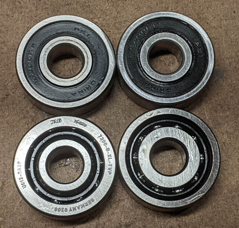
The bearings on top are the old Y-axis deep groove ball bearings, on the bottom are the new FAG angular-contact bearings. They aren’t sealed, but the Y-axis bearing is very well protected.
To better be able to apply a reasonable preload to these ballscrew bearings, I also added a pair of Belleville disc springs. These are conical washers that flatten out as you tighten them. By adding a pair with the OD facing toward each other, you can put them on the shaft and by measuring how much you’ve flattened them as you tighten the nuts, you can also estimate how much axial preload there is in the bearing. This worked quite well.
The drawback of using these springs is that, well, now you have an axial spring. This means that if the motors apply enough axial force on the ballscrew, these springs can compress which translates to uncommanded motion of the table. The X- and Y-axis motors have a peak torque of “290 oz-in”, which in reasonable units is 2.0Nm. The pitch of the ballscrew is 5mm per turn, so assuming perfect efficiency, this corresponds to a peak axial force of 2.0*2*pi/0.005 = 2.5kN. Based on the specification of the belleville washers, I estimate the preload to be about 1 kN, so it seems it is possible for the motor to compress the washers. (On the other hand, the table weighs about 14kg, so to apply that force would mean an acceleration of about 7G. We never get even near that, so the question is whether the cutting forces ever come close to a kN. I could test this by hooking up the USB cable to the servo and reading out the peak torque while running a heavy cut. I haven’t tried that, it would be an interesting exercise to perform. Anyway, I’m digressing.
After assembling the mill with the new bearings and coupler, I was playing with the servo settings, crashed the X-axis into the hardstop, and promptly broke the X-axis coupler, too. Sigh. I only ordered one since I didn’t know how well they would work, but since they seem fine I ordered similar ones for the X- and Z-axes, too. I assume it’s just a matter of time until the Z-axis coupler breaks, as well…
Another thing I noticed after taking the mill apart was that the Y-axis gib seemed to only contact the way along the edge. I suspect this is because of the way the set screws contact it. A while ago, I modified the X-axis gib by milling bona fide flats in it where the gib screws could contact. This not only provides a flat surface for the screw to bear on, but also positively locates the gib so it can’t move around. Since I still had the fixtures I fabricated for that modification, I decided to go ahead and do the same for the Y-axis.
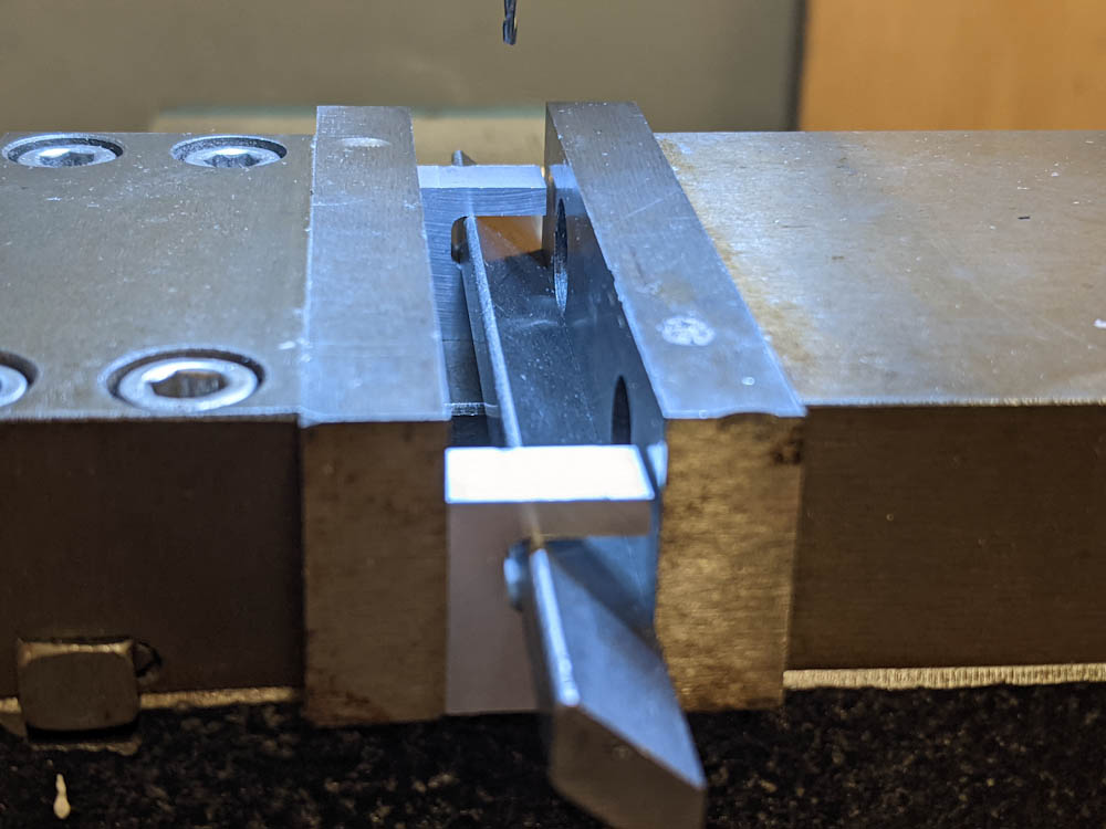
The Y-axis gib fiixtured in the vise using the custom-milled holders that make sure the gib is rotated the correct angle. Note that the holders do not contact the movable vise jaw on the right, it only pushes the gib itself.
This was pretty quick work since I just had to update the X-axis design in Fusion360. I also had to modify the CAM because I used a 3/32″ endmill originally but I no longer have any of that size. I had to use a 1/16″ instead.

The flats have been milled. They look pretty ratty in the picture but they’re fine.
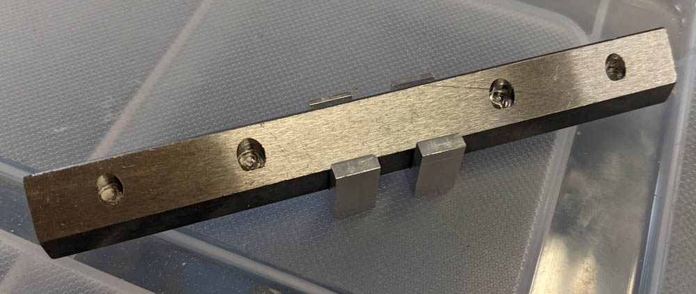
The completed Y-axis gib.
The holes in the new gib matched the position of the screws perfectly. The height of the flats could be changed a little bit to better center the gib on the dovetail, but it should still contact the flat instead of along the edge. We’ll see if this makes it easier to adjust the gib to be tighter without having it bind. There was a very noticeable play in the Y-axis before.