Since the last post, the fan bracket for the heat sink has been completed.
Since it had to fit quite precisely in place below the heat sink on the side lid, I glued a piece of urethane foam in place and cut it to the correct shape and rounded the corners a bit. Then I covered this in plastic film and made the layup over it, wrapped the whole thing in plastic film, and applied vacuum.
I initially only used a single ply, but this didn’t work at all, the vacuum squeezed it and got rid of so much resin there were holes right through the weave. It was also way too flimsy. It had to be redone with two more plies to get it reasonably stiff.
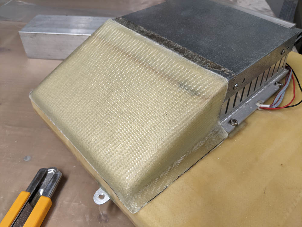
Test fitting the fan holder for the dehumidifier heat sink.
After curing, it fit very nicely to the shape of the heat sink and the side lid, not surprisingly since it was shaped to it. Then the holes for the fan screws and the air passage had to be drilled and cut.
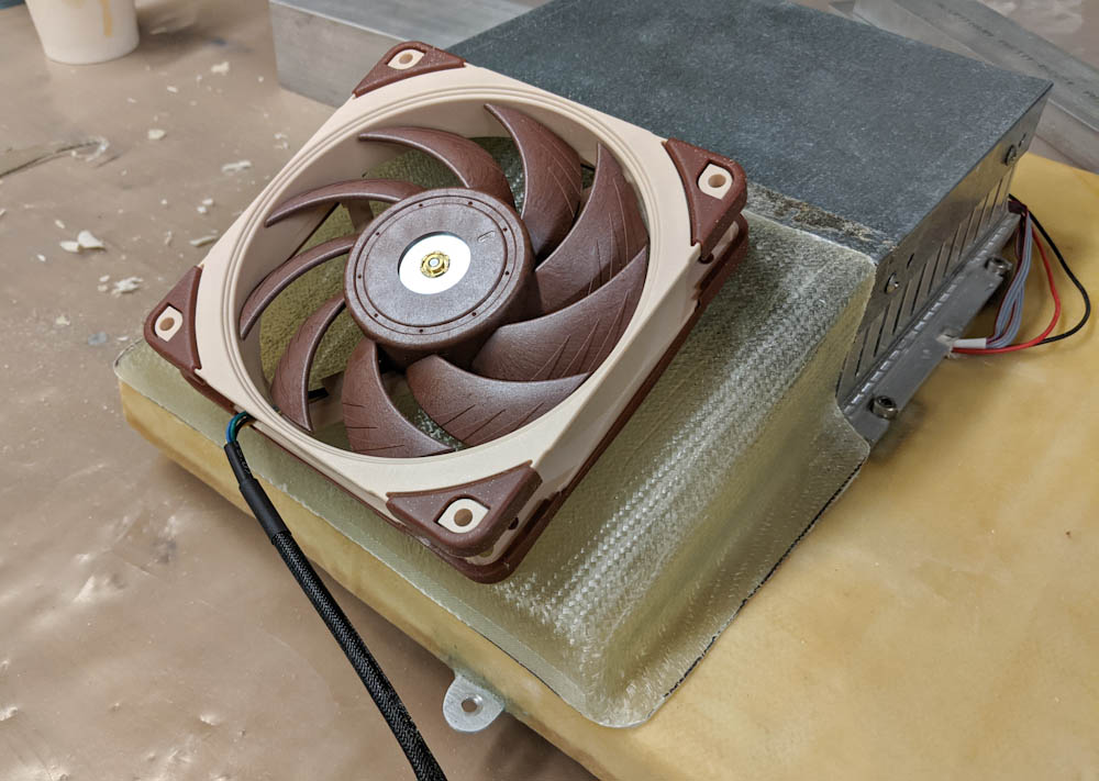
Marking out the position of the fan for cutting the holes.
I realized that it was not going to be possible to use nuts to attach the fan since you can’t get to the inside when the fan is mounted. Instead, I covered the fan in plastic, screwed it in place, and then applied flox around the nuts to stick them in place.
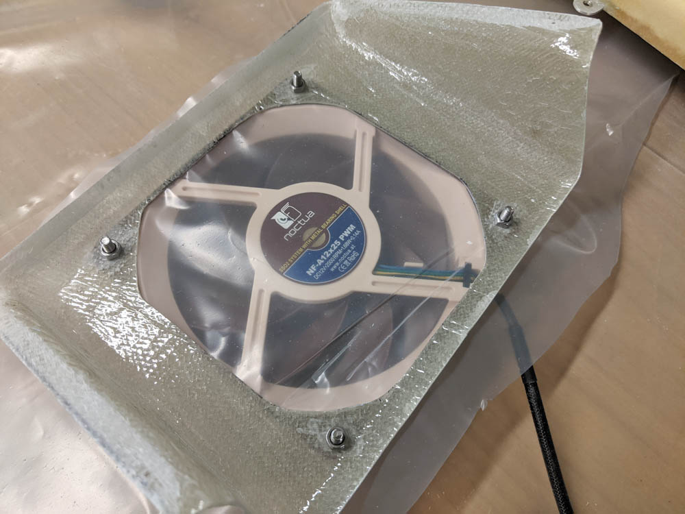
To make it easier to mount the fan, I screwed it to the bracket and then covered the nuts in flox (carefully so nothing got on the screws.)
Once the flox had cured, it was time to mount it by the heat sink. This was done by applying a generous coat of flox around the flange and weighting it in place. I had also drilled 4 holes for nails that ensured that it ended up in the right position.
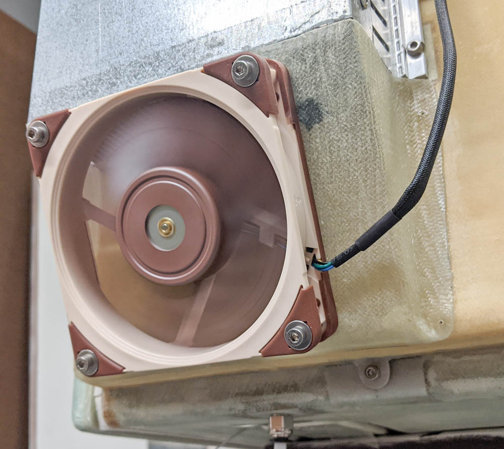
The bracket has been floxed in place below the heat sink. Here it’s running during a drying cycle. This worked out very nicely.
This ended up working really well. The fan fits perfectly, there’s a tiny gap between the heat sink and the fan holder that can be covered up in tape. You can feel a little air escaping through the gap but I don’t think it does much to the cooling efficiency.
With that, the glass work was done. Since then, I’ve been working on the software. It’s been quite tricky to figure out the best way to get moisture out, but things are converging. I’ll have more to say about that in the next post, but as a sneak peek, this graph shows the current temperatures and humidities:

Pingback: CNC mill upgrade: Spindle – Patrik's projects
Pingback: CNC mill upgrades: Couplers and gibs – Patrik's projects
Pingback: Filament storage part 20 – Patrik's projects