For my compressed air needs, I’ve so far used this 8-gallon Husky air compressor I bought back in Torrance, and while it’s been adequate, it can’t really keep up with really any use of air tools. Even just running the mister for the CNC mill, which doesn’t use a lot of air at all, it cycles very often. It’s also really loud, which is annoying to us and also apparently to the neighbors because we got a notice that someone’s lodged a complaint about “excessive noise from construction equipment”. I don’t know if it’s the air compressor or the long hours of sanding that was the culprit, but since the compressor was inadequate to begin with I decided to make some upgrades.
The only real step up, compressor wise, is to go to a 60-gallon one. These typically have 3-4hp motors and a capacity that’s about 4x that of my previous one. They’re still loud, but because they are belt driven and run at lower rpm, the noise is less bothersome. They also weight over 200lbs, so the only practicable way of getting one is from Home Depot. (For some reason, Amazon refuses to ship one Prime here…) Luckily HD had a 60gallon, 3.7hp Husky in stock.
To minimize noise, I decided this should go in the garage closet where the PV inverter is mounted. This is an internal closet so has no direct noise route to the outside except a few vents.
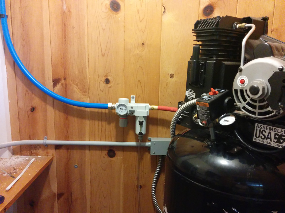
This is the 60-gallon Husky in its closet, with a new, larger filter/regulator.
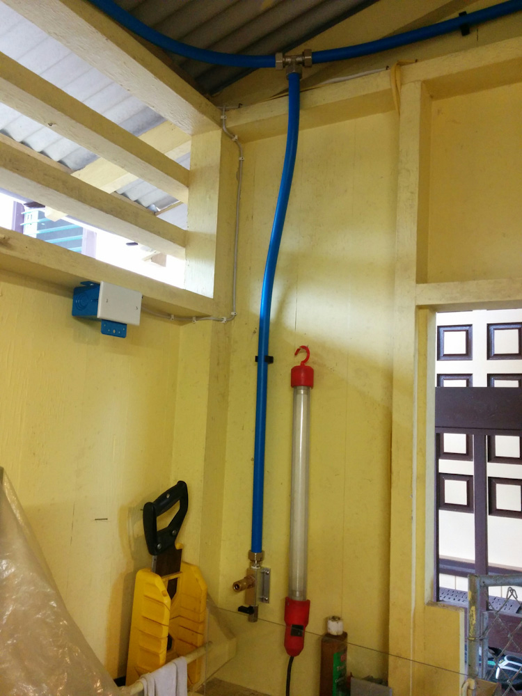
I’ve also gotten rather tired sneaking long air hoses around the garage, so I decided to invest in fixed air lines. There are various ways of doing this, you can use iron pipe, copper pipe, or other options. Since running iron pipe is a gigantic hassle, even if it’s cheap, I ordered a “Maxline” kit on Amazon. This is thin aluminum tubing with plastic cladding on the inside and outside, which means it’s bendable and goes together with compression fittings. The kit comes with pretty much all you need for a small installation, and even if the 3/4″ tubing isn’t super easy to bend, it went together pretty quickly. It took me a few hours across two evenings to install the kit, and I had absolutely no leaks.
This is going to be so much better than sneaking the long hoses around. If you use air a lot in your shop, I can totally recommend this kit (or the 1/2″ equivalent; The kits are the same price, and since I want to, at some point, run an air line into the basement, too, I went with the larger tubing.)
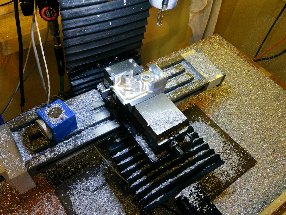
The kit comes with 3 of these Tees and outlets. This is the dedicated CNC mill outlet.
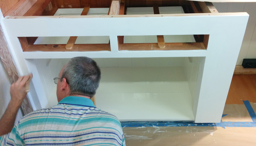
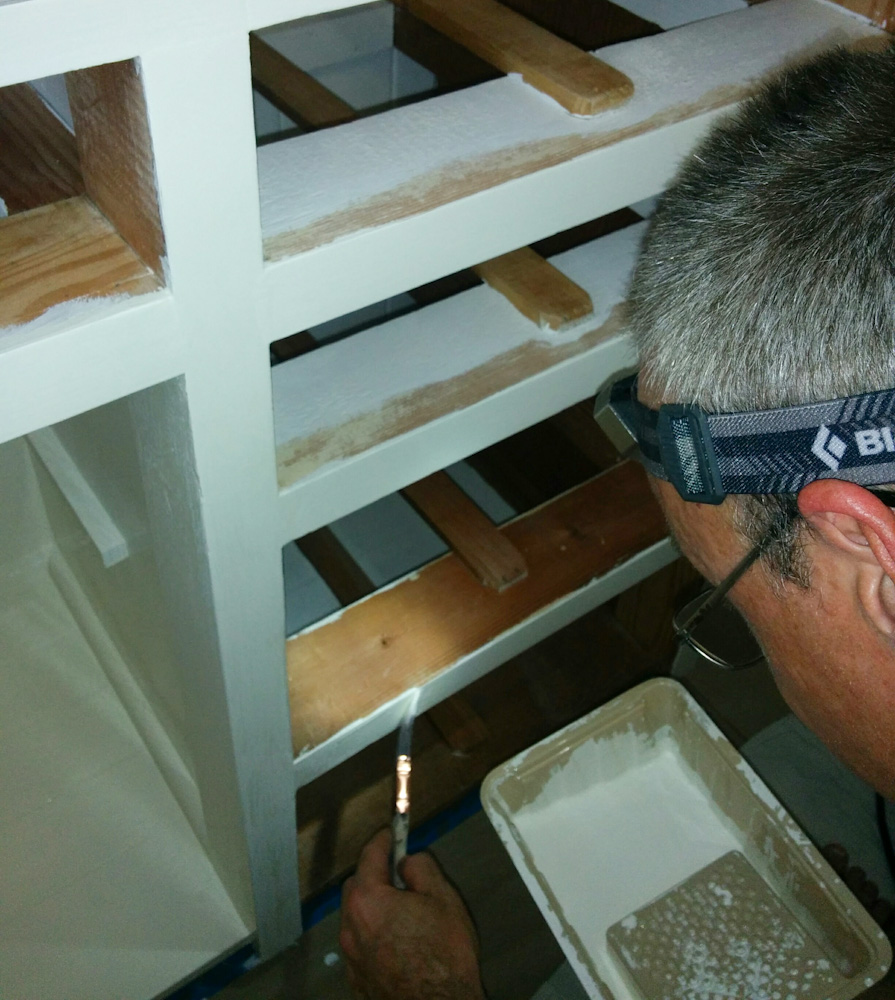
To further cut down on the compressor noise, I built a “box” around the motor and pump from 20mm MDF. It’s not enclosed, since the compressor needs air flow (it gets pretty hot even in free air, something about p-dV work I believe…) but it should prevent direct noise paths.
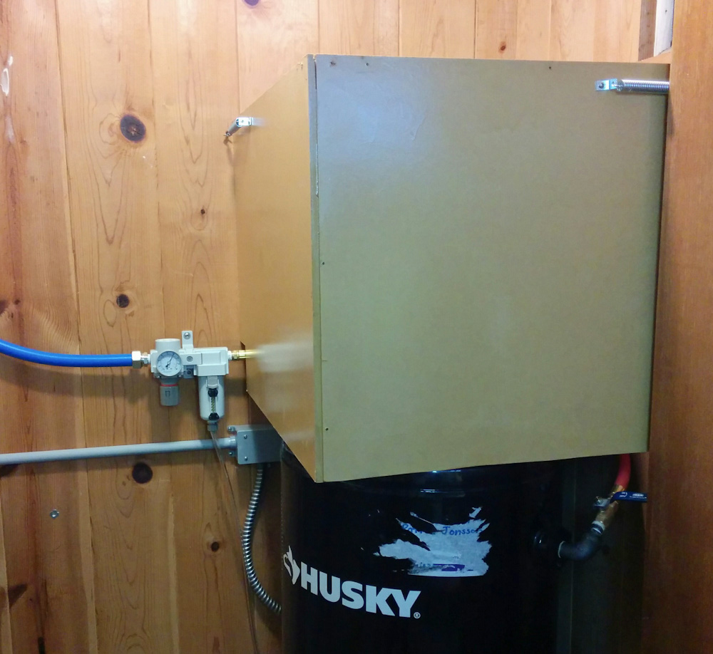
The noise suppression box doesn’t touch the compressor at all, it hangs on the wall and is open-bottomed. There’s also a large hole in the top where the heated air from the compressor fan can get out.
The box didn’t have any noticeable effect on the noise level in the garage as measured with the sound meter app on my phone. However, those are not very accurate. The noise did have a more muffled quality to me, so I suspect the higher frequencies are attenuated but the low-frequency rumble is not. I’m still going to line the inside of the box and the walls of the closet with fiberglass insulation to further try to attenuate reflections, so we’ll see if that makes a difference.
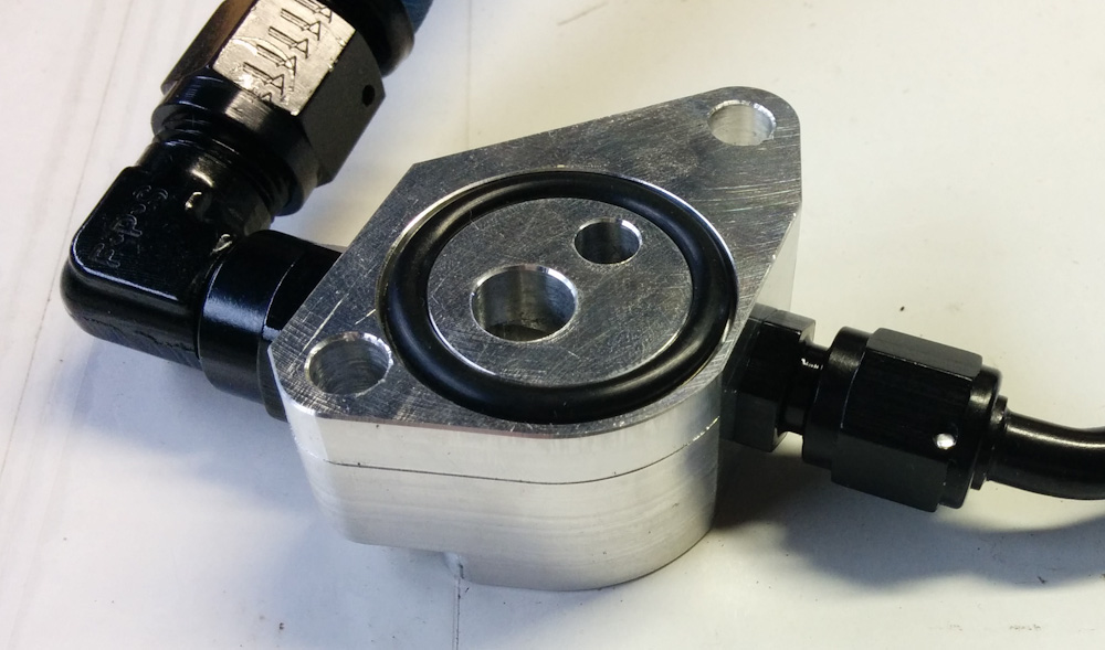
The other thing I’m going to do is replace the tiny foam filter for the pump inlet with a large Solberg filter. This should cut down on the intake noise which I think is a large factor. That however requires machining an adapter so it’ll be a few days until I can mount that.
So how much is it going to run? I’m not sure yet, but I measured that 4 minutes of the mister will drop the tank pressure by 10psi. Since the compressor pumps the tank to 150psi and the mister only uses 50, I could in theory run it for 40 minutes without needing to start the compressor. However, I’m not sure at what pressure the compressor cycles, so it remains to be seen how long it can go without kicking in. I’m sure it’ll be a whole lot less than the old one, which could only go for about a minute before starting up again.