With the fuel rail parts completed, it was time to assemble it and see if it worked.
Step one was to replace the seals on the injectors. I’d ordered a replacement seal kit from “Mr Injector” a while ago but didn’t want to replace the existing O-rings until I was mostly done with all the test fitting. I can’t make that excuse any more.
Before replacing the O-rings, I actually hooked them up to the “test port” that I used for leak checking and flushed some carb cleaner through each of them. Since there’s some volume inside the part, I could undo the air hose, fill the injector holder with carb cleaner, reattach the air hose and then pulse the injectors to spray the cleaner through. A couple of them did not particularly want to do anything for short pulses, but after blowing a couple of loads through them they all seemed to behave better. I hope I’m not going to have sticky injectors after going through all this…
Replacing the seals was mostly painless except to get the fuel strainer cups out I had to screw in a sheet metal screw and pull it against a pile of washers. According to the instructions, it should work to just pull them out by hand, but mine did not budge when I tried that.
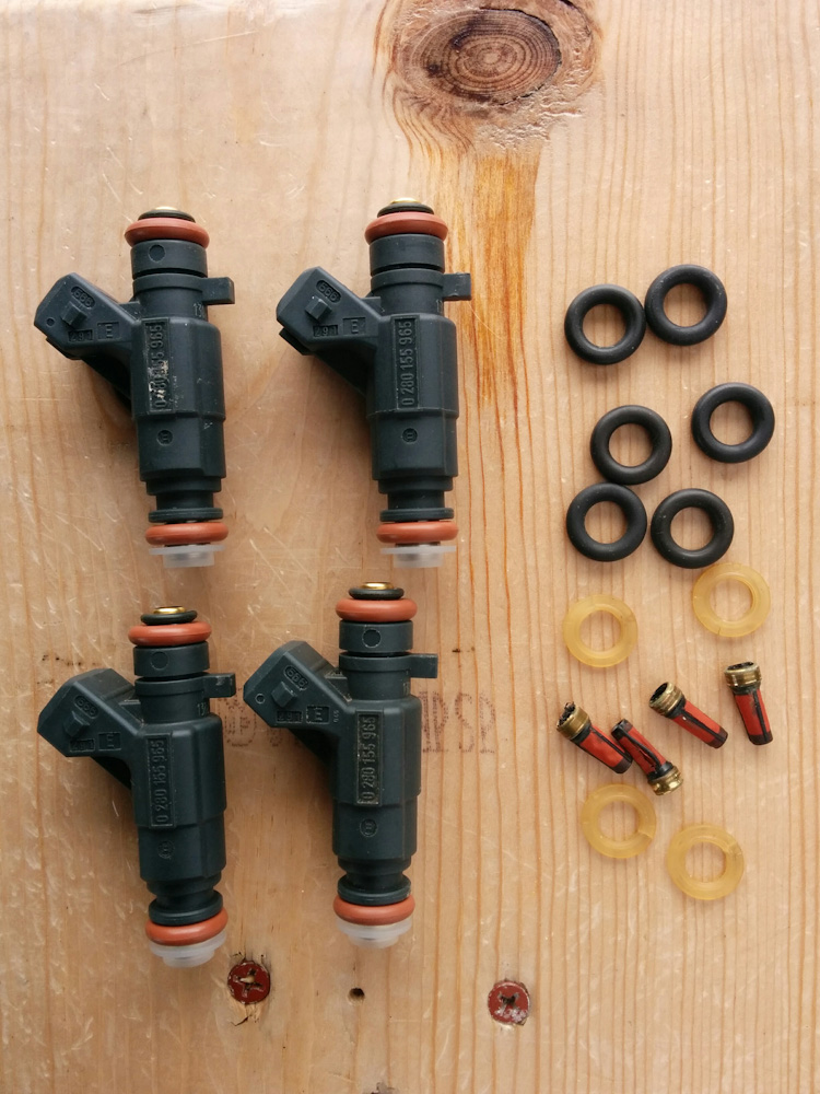
Here are the injectors, complete with new Viton O-rings, filters and retainers.
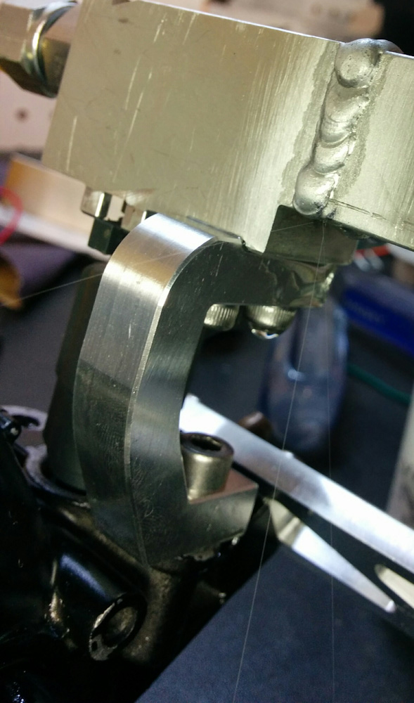
Step two was to hook up the compressed air hose that I used to leak-test the O-ring ports to the entire fuel rail and see what happened. One thing I noticed was that I have a tad too much space between the fuel rail and the throttle bodies. It looks good when first put together, but when you pressurize the fuel rail, the injectors are pushed downward and actually move far enough that the “tab” (on the top right in the picture above) almost ends up below the guides I machined into the fuel rail. The space between the throttle body and the fuel rail is what is recommended in the data sheet, but they also assume that the injectors will be held in with little clips. It doesn’t leak, but it’s far enough out that you might be able to rotate the injectors which isn’t supposed to be possible.
In hindsight, I could have machined slots for those clips into the fuel rail, and then the injectors could have been locked into the fuel rail. That would have precluded them moving, and it would also have been easier to test them than now when I have to tie them up with wire to prevent them from shooting out when the rail is pressurized. Oh well… I’ll think of that on my next EFI conversion.
The other thing that was immediately obvious when the fuel rail was pressurized was a hissing sound. A leak… now what could be leaking, the injector O-rings, the AN-port O-rings, or my welds?
If you guessed the welds, you were correct. There was a corner in the weld to the square tubing that looked a bit low and incompletely fused and, sure enough, that’s where the air was coming from. After dismantling everything again, I added a few quick beads there and after reassembling the hissing sound was gone.
Step three, I now decided, was to go ahead and attempt to pump gasoline through and see what would happen. Alongside all of this I’ve been attempting to find a good spot for the fuel pump. Because there is just no space near the tank, I had settled on the tool kit pocket on the right side of the tail. I knew this wasn’t optimal, but it was just very difficult to fit the inline fuel pump, with inlet and outlet on opposite sides, in the battery area; there’s a fair amount of space there but it’s not long enough in any of the dimensions to easily fit the pump.
The problem with putting it under the tail is that the fuel line from the tank has to do a 180 (because the fuel tap outlet is in the forward direction) then go back to the pump, and then make another 180 before getting into the pump. This is uneven enough that there’s air trapped there, and it turns out that while the pump can get enough suction to suck the air through and fill the line with fuel when there is no back pressure, when it attempts to do that against the fuel pressure regulator it doesn’t work. It just sits there and spins air. This will require a wholesale redesign, but I’m leaving that for another post.
To make progress now, I manually primed the pump by disconnecting the hose going to the fuel rail and running the pump until it had filled it with fuel. Then I reattached it and restarted the fuel pump, and now it did build pressure.
I was now greeted with numerous small puddles of gasoline forming on the table. Apparently there were more pinholes in the welds; too small to hear air coming out but apparently not too small for fuel to go through. It was actually pretty cool, in one area there were numerous super-tiny streams of fuel escaping.
See the three tiny streams of fuel coming from the lower corner of the injector block?
On the other rail, there were no streams of fuel but gas was seeping out and gradually covering the top surface. It was hard to see where it came from, but I was pretty sure I knew which weld was the offending one.
Ok, time to dismantle again, although now everything had gasoline in it, so that was a messy ordeal. After wiping everything up as best as possible, flushing alcohol through the rails and blowing it out with compressed air, I left the garage overnight to air out and to deal with my gasoline-induced headache…
The next day I ground the welds down, cleaned them as best I could, and gave them another pass. This time I tried to make them on the hot side to make sure the welds penetrated.
I wasn’t about to try to reassemble the whole thing again, so now I just put the injectors and the fuel pressure regulator back, hooked up the compressed air line, and dunked the whole thing in a bucket of water.
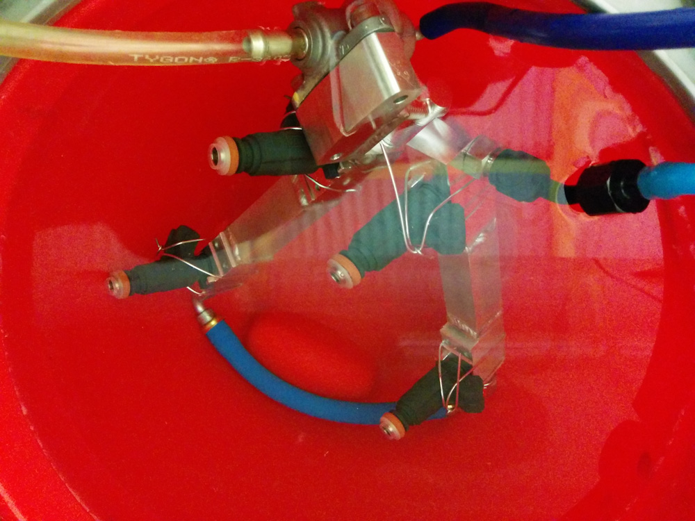
Now, with the whole shebang hooked up and underwater, I’m pretty sure there aren’t any leaks. Except maybe from one of the injectors…
It’s apparent from this exercise that you have to tighten the steel AN flared fittings quite a lot to get them to seal. They warn to not tighten aluminum ones too much, for obvious reasons, but there the sealing surfaces are softer and you probably also don’t need to. In the end, I could pressurize the whole thing to 3.5bar, when the pressure regulator starts to open, and it was all tight except occasional bubbles coming from the end of one of the injectors. Maybe I need to squirt some more carb cleaner through them…
While I’m thinking about how to redo the fuel tank plumbing, I’m going to hook up the injectors again and measure their flow rates and dead times (how long it takes the injector to open after the current is turned on). While I know what the flow rate is supposed to be, knowing these quantities accurately is necessary to be able to calibrate the fuel delivery in the Microsquirt.
Doing these measurements should be a simple albeit perhaps tedious exercise. I’ll squirt a number of pulses of various lengths into a container and weigh how much fuel is delivered. It’ll be just like a physics lab, complete with plots, except with flammable liquids and noxious fumes! Stay tuned
You made the comment about pressurizing the fuel rail to 3.5 bar (50psi) for testing and also mentioned that this is the pressure at which your pressure regulator opens. Are you planning to run the bike at 50psi?
Also, regarding your concerns about fuel pump location, I went through a very similar series of realizations while working on my GSF400: space issues, where to put it so that gravity could flow fuel from the tank to the pump, how to route the fuel plumbing (as efficient and as short as possible, with as few connectors as possible). In the end I decided to move a bunch of things around to allow fuel pump placement in an optimal position. The main item in this relocation process was the bike’s battery which occupied a large piece of the prime real estate just aft of the airbox. This was the obvious position for the fuel pump to occupy.
I moved the bike’s battery into the tail (under the rear seat solo cowl), also moved the fuse box into the tail, moved the radiator overflow bottle rearward into the space previously occupied by the fuse box and moved the starter solenoid off to one side (mounted on the side of the new fuel pump bracket).
The fuel pump I’m using is the Honda TRX500 Rancher unit. The good and bad: The good side of this pump is that it has all of its connections on top, also it contains a good-sized volume of space inside the housing to act as a “swirl pot” and inside that space is a built-in (but replaceable) sock-type fuel filter and a pressure regulator and this fuel pump is readily available from parts suppliers for about $100 (amazingly cheap). The bad side is that this pump is a bit on the large side (approximately equal to the size of the bike’s battery).
I used a high pressure fuel filter from the GMC Envoy SUV. It also has its connections located on one end (I mounted it vertically, just behind the fuel pump, right next to the relocated position of the radiator overflow bottle).
Yeah, this appears to be the pressure setting on the regulator (it’s from an F4i, I believe).
I can’t move the battery back, there’s no room under the tail (already taken up by the Microsquirt, fusebox, and the wideband controllers) but I’m going to switch to a lithium battery that’s a lot smaller, so there’s some room in the battery box even without moving it. On the VFR, everything is super tight, the radiator bottle is molded to curve around the subframe, I don’t think there’s any way to move that.
I think I looked at that fuel pump unit, it would be nice to have the little “surge tank”, but there’s just not enough space for it. The filter I’m using is a small Wix 14 micron filter, it’s small enough to not be a problem. An SUV filter sounds like it would be huge?
Here’s a recent “walk around” video of the GSF400, the GMC Envoy fuel high pressure fuel filter makes a couple of appearances.
http://vid679.photobucket.com/albums/vv158/EWflyer/GSF400%20video%20library/GSF400%20project%20tour%20-%20April%2016-16_zpsnyukevn5.mp4
Cool! But OMG, look at all that space. You can see right through the engine! 🙂
Pingback: Microsquirting the NC30, part #21: Injector characterization – Patrik's projects
Pingback: Microsquirting the NC30, part #23: Fuel pump housing – Patrik's projects