- In the previous post I talked about making the antenna for the weather station. Now, what’s that antenna connected to?
An XBee-only solution?
The initial iteration, that I talked about in the first post, was to just hook up analog humidity and temperature sensors to the XBee’s analog inputs. However, I had trouble getting the readings to be reliable. Even after adding an opamp buffer to the humidity sensor output, it would show weird shifts where the reading would look OK for several hours and then, all of a sudden, drop by tens of percent.
The other problem was that I wanted to add more sensors, like pressure and light, that only were available with I2C connections. I2C is a simple digital communications bus that uses two wires, clock and data. The XBee can’t speak I2C, but you can emulate it by sending commands to switch the digital outputs and read the digital inputs. I wrote some Python code that would talk I2C through the Xbee in this way, and it actually worked. The problem is that it’s agonizingly slow. A common speed for real I2C connections is 100kHz, with the Xbee I managed at best 5Hz! At that rate, it took 30s just to measure the light from the TSL2561 light meter I got. Apart from taking forever, this would also totally kill the battery life, because the Xbee not only would have to be awake but even be transmitting and receiving constantly. While an idle XBee uses 15mA, an XBee with the receiver on uses at least 35mA. This solution was not acceptable.
An Arduino+XBee solution?
If we instead offloaded all the measurement functionality onto an Arduino, we could let the XBee sleep for most of the time. A sleeping XBee uses less than 1uA (that’s micro amp), so that would save a bunch of power. Of course, instead we’d need to power an ATmega 328, but an active ATmega 328 running at 3.3V, 8MHz, only uses about 4mA, and it can quickly go idle and only use less than 1mA. From a power consumption standpoint, this is a far superior alternative.
Further advantages are that an Arduino talks I2C natively, so talking to I2C sensors is quick (and reliable), and things like the wind meter, which requires measuring how many times per second it closes its switch, can be done efficiently by letting the microcontroller sleep for most of the time.
Finally, a reliable I2C connection meant that I could get rid of most of the flaky analog sensors and not have to worry about analog noise, buffering the sensor outputs, etc. On top of that, I’d already bought a few 3.3V Arduino Pro Minis from Sparkfun for $9 when they were on sale. This was the way to go!
Sensor inputs
Now that I could easily interface with many different sensors, I could go to town. These are the sensors I used:
- Temperature and humidity, using an HTU21D I2C sensor.
- Barometric pressure, using a BMP180 I2C sensor.
- Ambient light, using a TSL2561 I2C sensor.
- UV light, using a ML8511 analog sensor.
- Rain and wind with Sparkfun’s weather meter kit. The rain is measured by counting the number of flips of a tipping bucket, each generating a momentary closure of a switch. The wind speed is measured by measuring the rate of closure of a switch connected to the anemometer, and the wind diection by measuring a resistance.
In addition, I’m monitoring the battery voltage and the supply voltage to the Arduino. The 1000mAh Li-ion battery is charged using a solar cell and Sparkfun’s “Sunny Buddy” Li-ion charger. The charger has two outputs, “charge” and “fault”, and those are also monitored.
The hardware
Rather than go through all the iterations, I’m just going to present the final product. It looks like this:
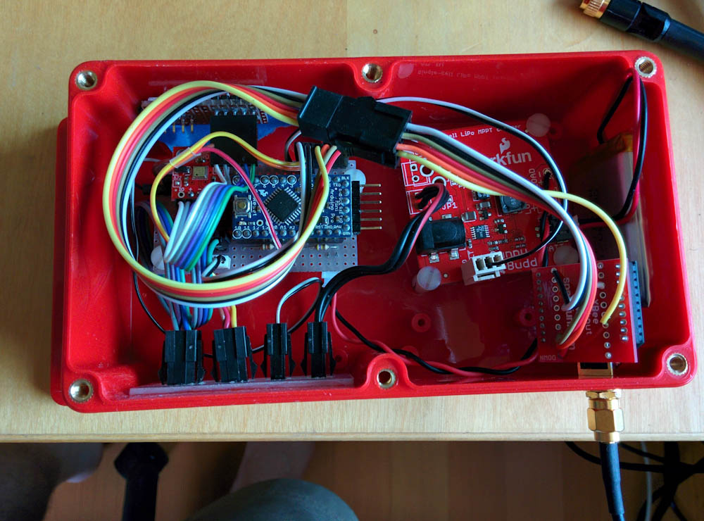
Here’s the weatherstation hardware, mounted in the watertight box. The Arduino Pro Mini, mounted on a little stripboard, is on the left, the solar battery charger on the right, and the XBee attached on the bottom right with the RP-SMA antenna connector coming out through the box.
Since the Arduino Pro Mini is a tiny board, I used a piece of stripboard that I had lying around to make connections. A JST connector connects the battery charger to the board, and the 3.3V regulator on the Arduino board also supplies the XBee and the sensors with 3.3V power
There are 3 connections to the I2C sensors, the pressure sensor (visible as a little red breakout board to the left of the Arduino in the picture), the light sensor (mounted at a little window cut in the top wall of the box), and the temperature/humidity sensors, which are mounted in an external housing and connected to the box with one of the black micro-fit connectors.
The two digital inputs, charge and fault, from the battery charger are connected with the “computer fan” connector along the lower end of the battery charger board. These are open-drain outputs, so the built-in Arduino pull-up resistors are used to convert them to high or low inputs.
The analog inputs require a bit more circuitry. Since the A/D converter measures voltages relative to a reference, we need a known voltage to compare to. Luckily the Arduino has a built-in 1.1V voltage reference that can be used for this purpose, but the hitch then is that all voltages must be converted to be no higher than 1.1V, since that’s the largest voltage that can be measured. The supply voltage measured through a voltage divider of 100k/470k ohm, which gives us a max measured voltage of 6.3V which is plenty since the Li-ion battery maxes out at about 4.3V.
The UV sensor, which is mounted along with the light sensor in the window of the box, also outputs a voltage that’s higher than 1.1V, so it’s also connected through a voltage divider, 100k/220k ohm.
The wind direction meter also is read with the ADC. Depending on the wind direction, there are 8 different switches that can be closed, each connected to a different resistor. By using this unknown resistor as one part of a voltage divider, we can measure the voltage and calculate the resistance. However, the resistance of this divider is fairly low, it’s a fixed 10k resistor and a variable one that can be even lower. Hence, the divider would consume quite a bit of current if it was always powered. Instead of connecting it to the supply voltage, it’s connected to one of the Arduino digital outputs, so it can be turned on when making a measurement and kept low when not. That way, it’s only consuming power when needed.
Finally, the wind speed and rain meters are just switches, so they are connected between a digital input and ground, using the internal Arduino pullup resistor. Thus, when the contact closes, the input will go low, and this can be detected. I’ll have more to say about this in the software post, but the Arduino has interrupts that can detect when an input changes, and even at what time, so this makes it possible to keep monitoring these even when the Arduino is sleeping.
That’s pretty much it for the hardware. It’s all mounted in a weatherproof enclosure out in the yard, with the wind meters on a tall pole to get above the trees:
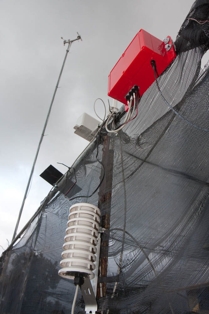
Here’s the weatherstation hardware. The temperature and humidity sensors are in the shielded enclosure at the bottom and the wind meters on top of the tall mast. The solar cell, rain bucket, enclosure, and the antenna are all mounted on the frame of our “greenhouse”.
I’ll write more about the software later, but it’s working. This is nice, because we’re getting hit by a hurricane later today, so it’ll be interesting to see the data (and see if anything blows away).
To wet your appetite, here’s the real-time measured wind and rain:


The link to all the plots is here. I’ll write more about the software once the hurricane has passed — assuming the house still stands!
Jiiisus, lots and lots of work! 10 years ago we bought things like this at Clas Ohlsson, but these days we just download an app! 😉
I don’t want to leave my phone out in the rain mounted to a pole though… 😉
Pingback: The fight against water continues | Patrik's projects
Pingback: A Weatherstation Update – Patrik's projects