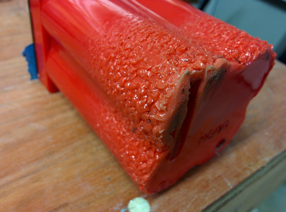
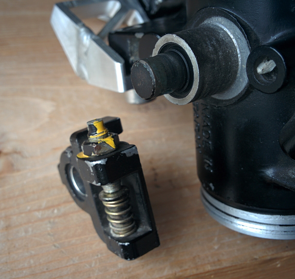
As the last post ended, I had to pull out the welder and fix the leak in the fuel pump housing. Even though it’s been a while since I welded aluminum last, the corner weld worked OK. There were a few little snags but after letting it cool down I put the housing under water and pressurized it again and the leak was fixed.
At least the hole I had welded up was fixed… but when I blew into the inlet as hard as I could, I noticed a tiny, tiny stream of bubbles coming from another spot (another one of the trouble spots from welding it together.) That was not an inside corner, though, so it was a quick fix and then I could not get any bubbles no matter how hard I blew. Calling that good!
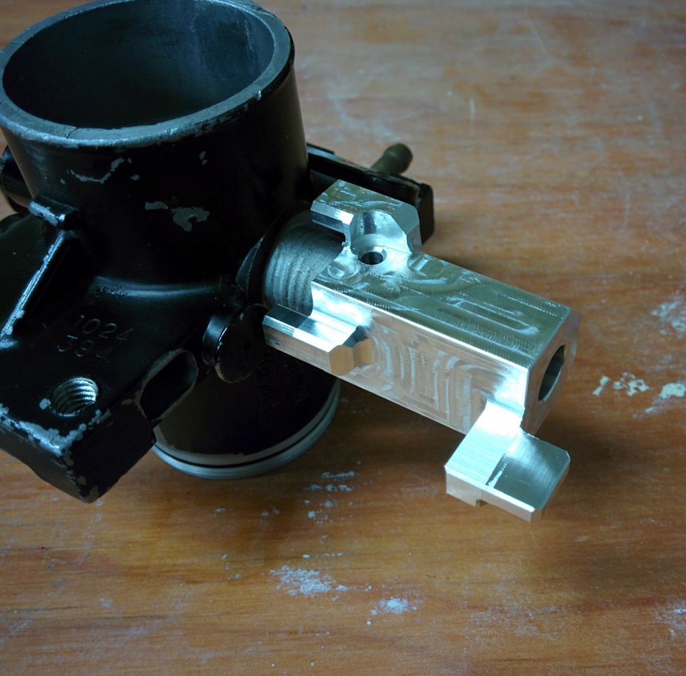
After putting the pump housing back together, there was one more thing I wanted to take care of. I have been meaning to fabricate a bracket to hold the inline fuel filter in place. I didn’t bother with it for just getting the motor to run, but it’s only held in place by the hoses and it has been vibrating against the top of the cylinder head cover so that definitely needed to get done.
Emulating the approach used to hold the wire harness on the other side of the crankcase breather, I meant to make a bracket out of stainless sheet metal. I had some ~1mm thick stainless (probably 18ga), but I wasn’t sure how to cut it to shape. After reading answers to similar questions, I decided to try to superglue the sheet metal to an aluminum base.
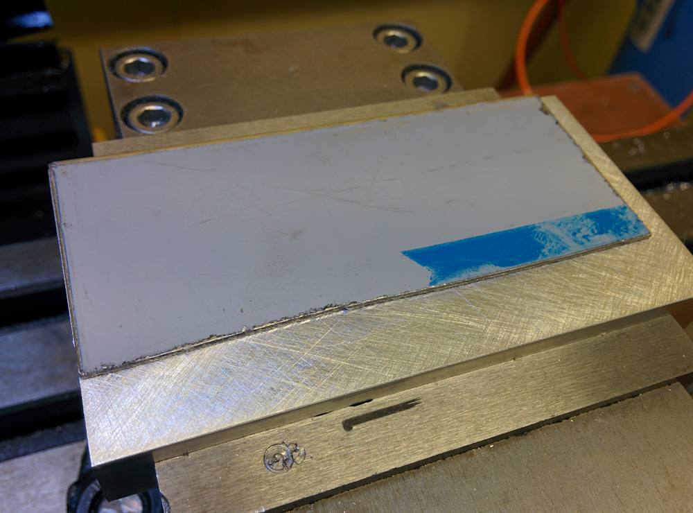
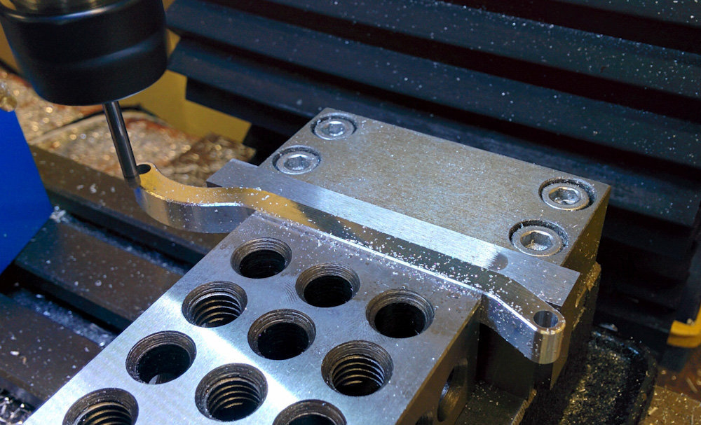
The starting point was to fix the stainless sheet to the aluminum base using superglue. After clamping it for an hour, it seemed to be stuck.
The first thing to do was to drill the mounting holes. That way, if the superglue didn’t hold, I could at least screw the sheet to the base using those holes.
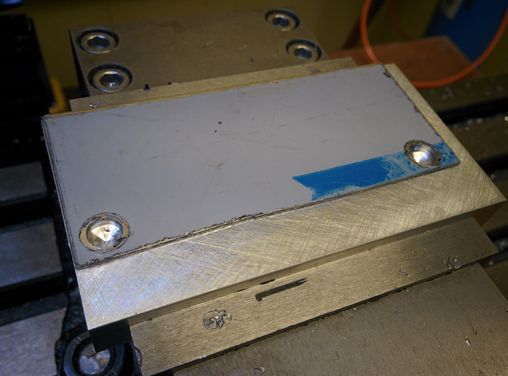
The superglue held up for drilling the screw holes, but when the endmill started clearing the material off the side it didn’t last more than 20s.
This would be the first time the mini mill would cut stainless steel. I was using a 1/8″, 5 flute, carbide endmill from Lakeshore Carbide that’s specially designed for stainless. I’d picked this up a long time ago because I figured it would come in handy at some point. Cutting stainless is kind of hard, because it work hardens and if your endmill isn’t sharp things can go downhill rapidly. (Check out this NYC CNC video, for example.)
Turns out it was good I drilled those holes first, because the endmill didn’t get more than a few cm into the first cut before the sheet popped off. Oh well. I put it back and bolted it down and tried again. I wasn’t entirely happy with this because the two holes are even both on one side so I was afraid the cutting action would lift the sheet.
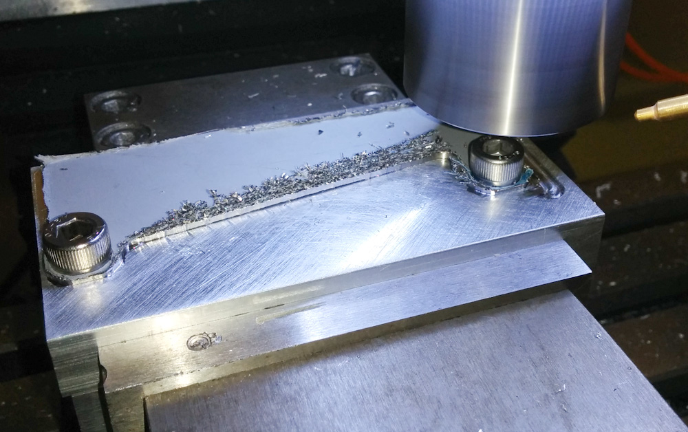
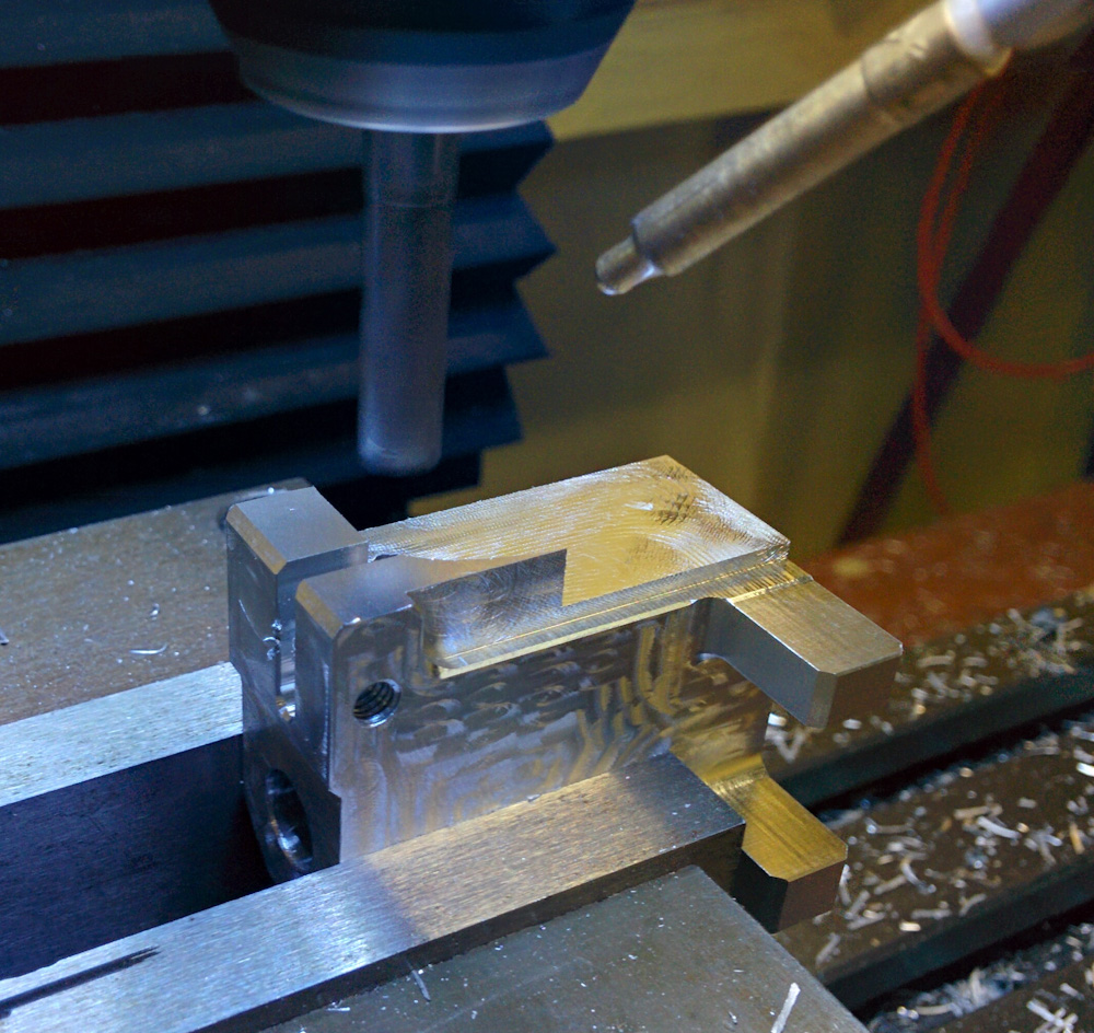
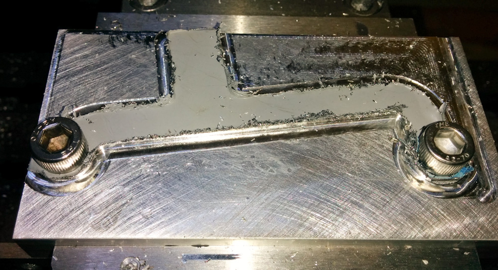
Halfway through the job. Having the piece bolted down in those two holes turned out to work fine.
Turns out it worked fine. I should have removed the plastic backing before starting, though, because it ended up catching the chips and holding them near the cut. No big deal, but I think it lead to some recutting. The end result wasn’t bad given that this was the first time I’ve cut stainless, but the piece definitely needed deburring.
Job done. Given that it was the first time I’ve cut stainless I think it came out fine, although the piece needed a fair amount of deburring.
I didn’t drill the hole in the tab where the clamp that holds the filter will go at this point, because I wanted to test fit it first. The position doesn’t have to be very accurate, so I mounted the bracket on the engine, held the clamp in position, and marked the spot with a marker. Then I bolted it back on the mill and manually moved it to that spot and drilled another hole.
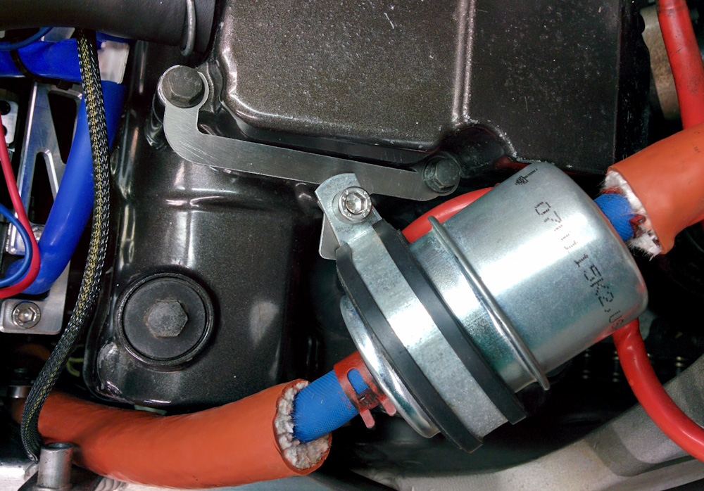
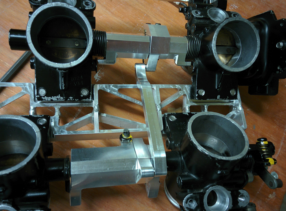
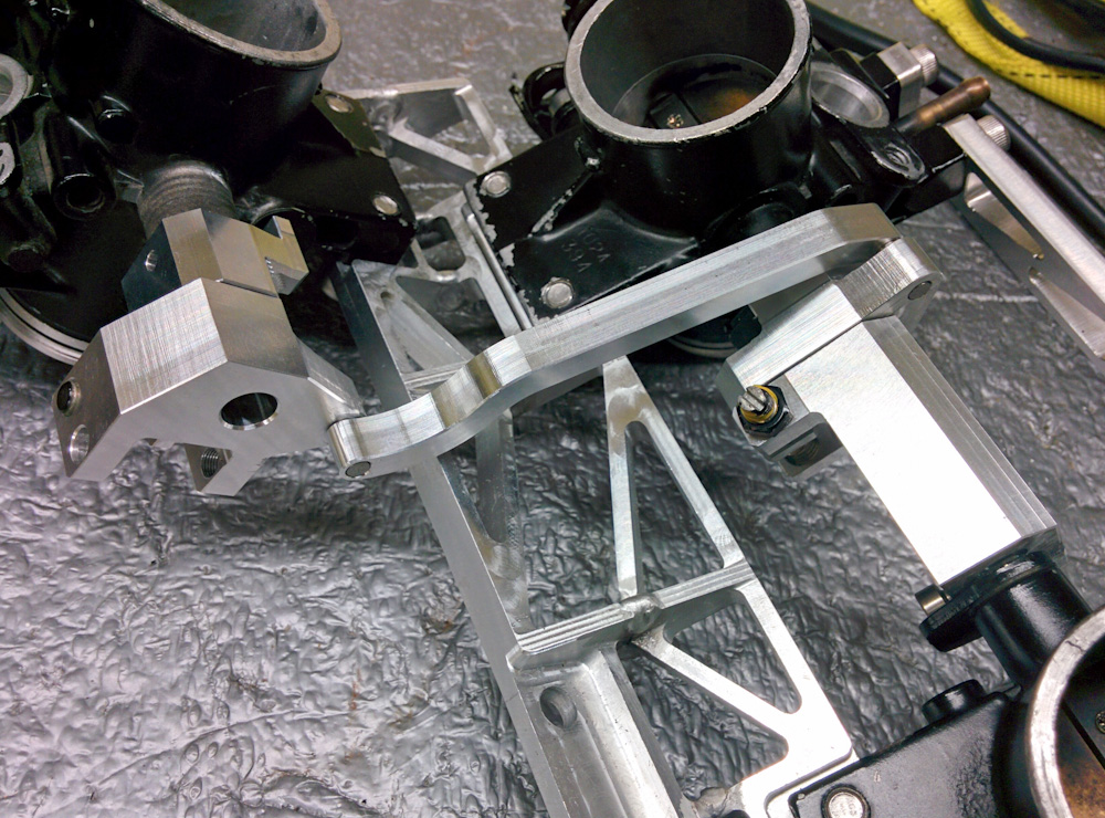
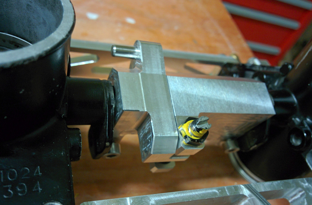
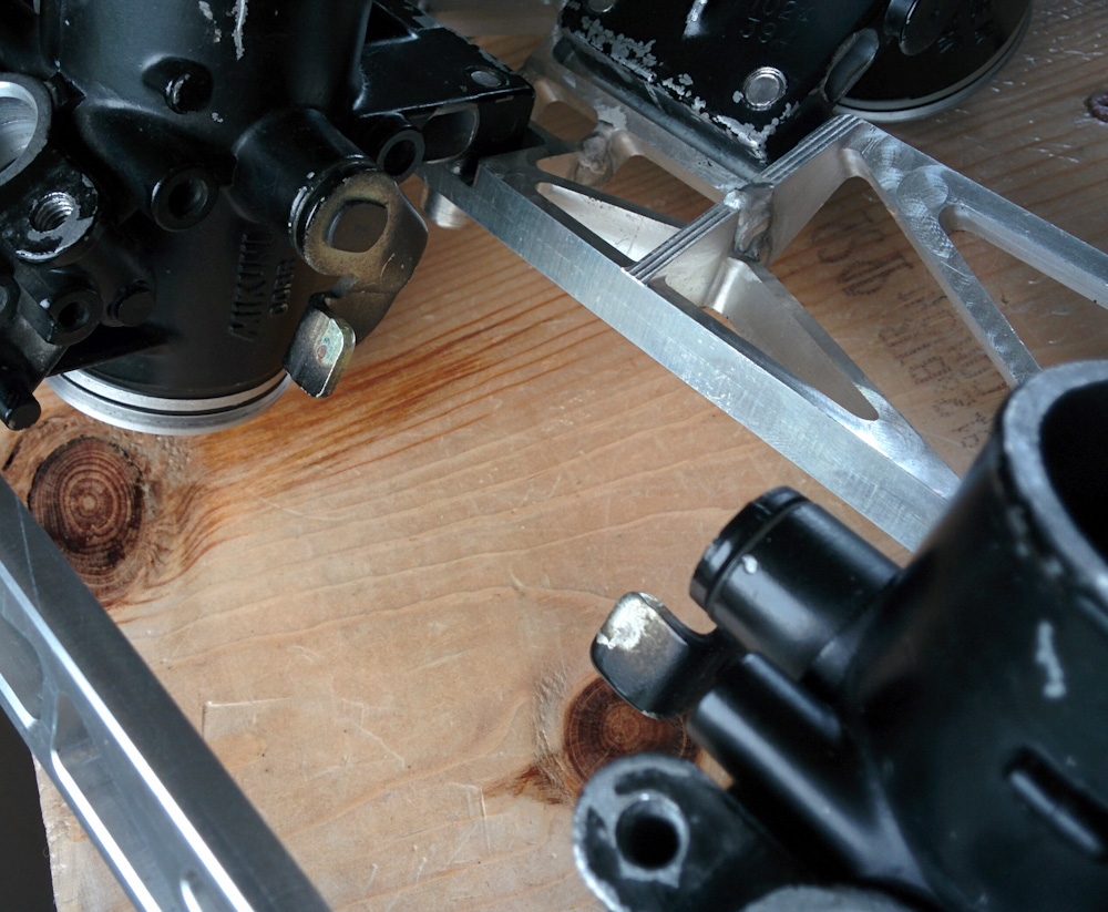
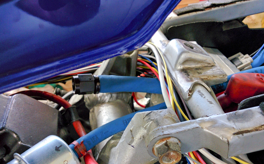
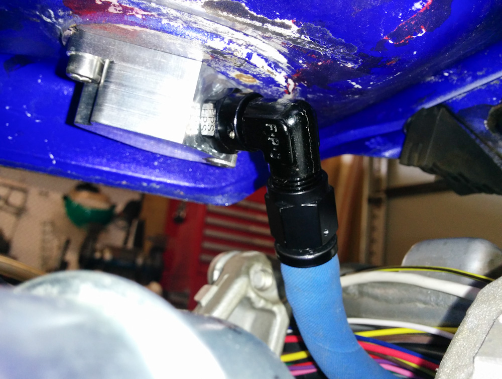
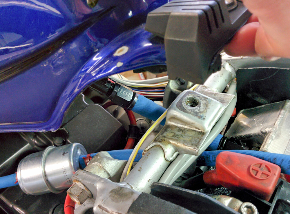
The final result: the fuel filter held in place with the bracket and the rubber-covered clamp. It’s not super tight, but all we want is to not have it vibrate around. I could have shortened the tab that the clamp attaches to since the hole ended up pretty far in from the edge, but it’s not a big deal.
The clamp had to be twisted a bit to point the filter in the right direction, but this is pretty good. The filter can’t really move front or back (left or right in the picture) due to the hoses, and the clamp holds it maybe 5mm away from the top of the head cover (right above the arrow on the filter.)
So now the filter can’t vibrate around any longer. Nothing fancy, but it should do the job. Time to put the bike back together and get back to tuning!