After fixing the fuel supply line, I finally got the fittings needed to hook up the fuel pump outlet line, too. With a 150-degree fitting after the fuel pump, it routed perfectly between the fuel pump housing and the battery.
Routing the return line was a little bit trickier. As shown in part 19 of this series, the fuel pressure regulator outlet faces downward, while the return inlet to the tank faces rearward. I had loosely assumed that it would be possible to make the hose do a 270-degree loop front, up, and then rearward, and come out reasonably aligned with the fitting on the tank. That turned out to be true, but the vacuum line to the FPR, which awkwardly faces straight out the side, runs right where the hose wants to go. It required a bit of jiggling while lowering the tank to not kink the vacuum hose, but it worked. It might be good to attach the hose somewhere to avoid it vibrating against the vacuum line, but for now it’ll work.
That completed all the required parts needed to start it the bike! First, however, I fixed a few small things.
The connection between the rear cylinder headers and the exhaust (the bent plate from the first exhaust post) had to be fixed. I straightened the plate in the vise, which wasn’t perfect but enough that it was possible to tighten. Then I replaced the rusted out flange nuts with brand new stainless ones, new gasket rings, and tightened it all up.
Another little fix was the heat shield between the rear headers and the rear brake cylinder. This had obviously been bent at some point, it was only attached at two out of the three bolt holes, and was also rubbing on the exhaust pipe. Some mild encouragement got this back in good enough shape to use all three bolts and not rub.
Now it was finally time to run it. I’m happy to say it started almost immediately when I was ready to try it, which was around 9pm on New Years Eve. I figured this would be the one day when no one would mind the noise…
The idle air valve seems to work as intended, and at full open it has plenty of air to idle the bike at around 1800 rpm even when cold. I’m going to call that a success!
The QuadraMap also works perfectly. Using the MAP logger on the Megasquirt tuning software you can sample the MAP value just as if you’d hooked it up to an oscilloscope, and you get four very nice dips from the four cylinders.
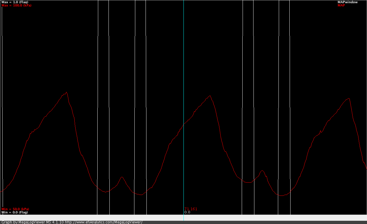
This is the manifold pressure log from the Microsquirt. The red is the manifold pressure, and the white lines represent the MAP sample windows when a measurement is taken. The graph has a MAP range of 50 – 100 kPa. For some reason, the #1 cylinder (the third dip on the plot) does not pull as low a vacuum as the others.
I had to play around with the injection settings a bit. This deserves a post all by itself, because it’s not very well documented exactly how the settings work, but I eventually got the bike running fairly well on “semi-sequential” injection. This means that the injection events are timed to the crankshaft position on the cylinders being injected, but that injection happens every crankshaft revolution. This means that one injection happens on the intake stroke and the other happens 360 degrees off, on the combustion stroke.
Since the front and rear injector pairs use share injector outputs, that’s the best we can do, but it fits quite nicely because the front cylinder pair is 360 degrees offset in the engine cycle. That means each of the two injections are appropriate for one of the two cylinders.
I captured a video of it starting and warming up. It’s not exactly riveting, but it shows how the Megasquirt tuning software works and gives you a chance to listen to a few minutes of V-4 idling…
As I mention in the video, the #1 cylinder had a tendency to not want to start and would die if the idle was lowered below something like 1500 rpm (1300 is factory idle). There are a few things that could cause this, basically bad compression or fouled plugs. It’s perhaps not coincidental that the #1 cylinder also can be seen to not have as good a vacuum on the MAP plot above.
I can’t check compression without taking the tank off, but I could get to all four plugs.
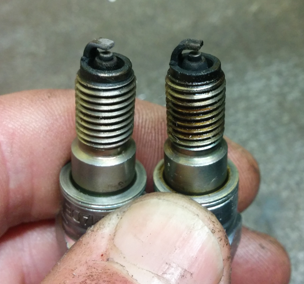
This is what the plugs looked like. Yeah, that’s pretty bad.
It turns out they all had a very dark appearance that strongly looks like carbon fouling. Since the bike has been running pig rich at least since I got it, that’s not too surprising. Luckily I had acquired four spares (the NC30 spark plugs are tiny 8mm ones that aren’t that easy to find) so I could swap them all out.
It seems that did the trick, it will now idle on all four cylinders, and I even got it to idle as low as 900 rpm without stalling. It’s not very happy doing that, but before one or even two cylinders would have dropped out and it would have stalled if I tried that.
I also had some problems with the communication to the wideband oxygen sensors dropping out. I was also seeing a lot of corrupted reads. Communication with the wideband controllers is handled by an Arduino that talks to them over I2C and sends the lambda values to the Microsquirt over the CAN bus. This was one of the first things done on this project and has worked solidly since then.
However, when I added the idle air control, I did a big cleanup of the Arduino code, and as part of that also changed the reading frequency from 10Hz to 100Hz, since that’s the frequency that the Microsquirt uses to read the value over the CAN bus. Maybe that was responsible?
Looking at the bus signals with the scope, it was clear that my 10k I2C pull-up resistors were on the large side. The size of those pullups are basically a compromise between signal integrity and power consumption but, with 10k resistors and the 100kHz I2C bus frequency, the signals barely had time to come up to full level. Changing those resistors to 3.6k made the signals look much better, and that’s still just over 1mA per line so there are no worries there.
I also noted that Alan To, the designer of the Sigma Lambda Controller I used, recommended a maximum polling frequency of 25Hz. I lowered it from 100Hz to 25Hz and with those two changes I have not seen any more hangs or corrupted reads.
I could play around more to tune the idle, but at this point it’s been proven to work so it seems to make more sense to take the throttle bodies off again and figure out how to set up the throttle linkages, which is the one remaining thing that needs to be done. Hopefully that won’t take too long to figure out.
Pingback: Microsquirting the NC30, part #37: Throttle linkage geometry – Patrik's projects