In the last post, the first half of the fuel rail, for cylinders 2 & 4, was made. Now it’s time to complete the other half. This will hold the injectors for cylinders 1 & 3 (the rear ones), plus the fuel pressure regulator.
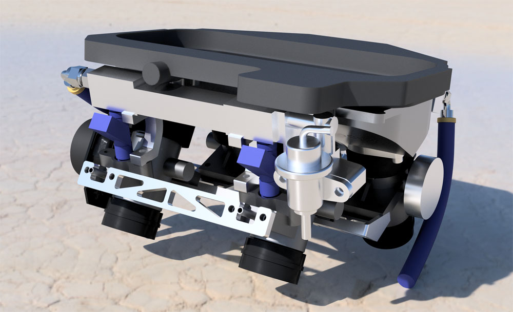
A rendering of the fuel rail for cylinders 1 & 3, with the fuel pressure regulator on the right.
I fiddled a lot with the fuel pressure regulator to get it to fit. As you can see in the rendering above, I settled on mounting it to the rear, with the fuel return going basically straight down and the manifold pressure port going out to the right. This fits, but forces the fuel return line to go down between the cylinders and then probably come back up between the two rubber boots. There’s just no way the hose can make the >90 degree turn needed to go immediately toward the rear. The manifold pressure line is just a small silicone hose that’s very flexible, so it should be able to handle the quite small radius turn it will need to do to avoid running into the tank.
Unlike the fuel rail on the other side, which only consisted of two pieces welded to the square tubing connecting them, the need to mount the pressure regulator (FPR) further down than the fuel rail itself necessitated making that side of 3 separate pieces: one for the injector mount, one for the FPR mount, and one little piece connecting the two, with holes crossing at 90 degrees for the fuel connection.
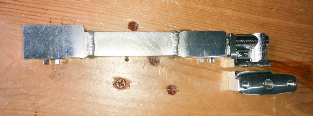
I’ve already welded the injector mounts to the square tubing in the middle here, so now it’s time to weld the two pieces on the right.
Given my welding skills, I wanted to avoid welding inside corners, because I know from past experience that those rarely come out pretty. For that reason, I made sure to make the “seams” between the pieces on sections that were straight. It also seemed like a lot of mass with those big pieces hanging out on the right side, so I had some fun designing the 90-degree piece to be as light as possible. It’s basically just a skin around the two holes, with a thin layer of material in the center. It looks pretty cool, but the CAM work is certainly not perfect.
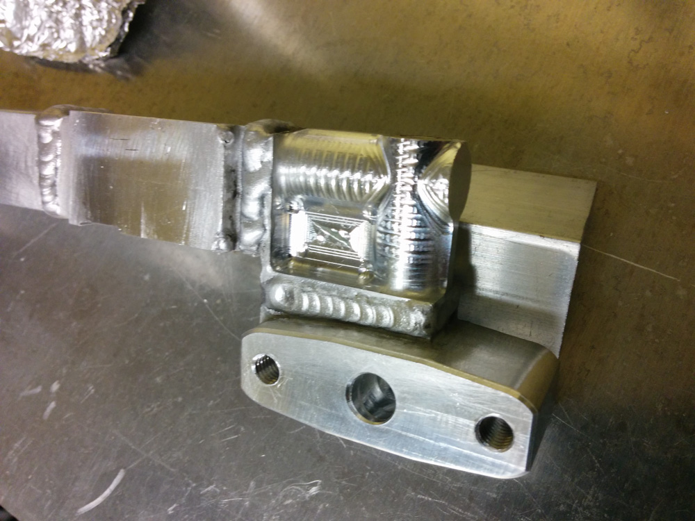
Here’s the welded piece. Most of the welds came out OK, but the weld on the left in this picture was close enough to the corner that I couldn’t prevent the arc from occasionally wandering off to the other side.
Since welding the other rail, I went through and tightened all the Argon gas connections on the welder, which actually seems to have helped. There seems to be less black junk in the welds now, but it’s certainly not anywhere near perfect yet.
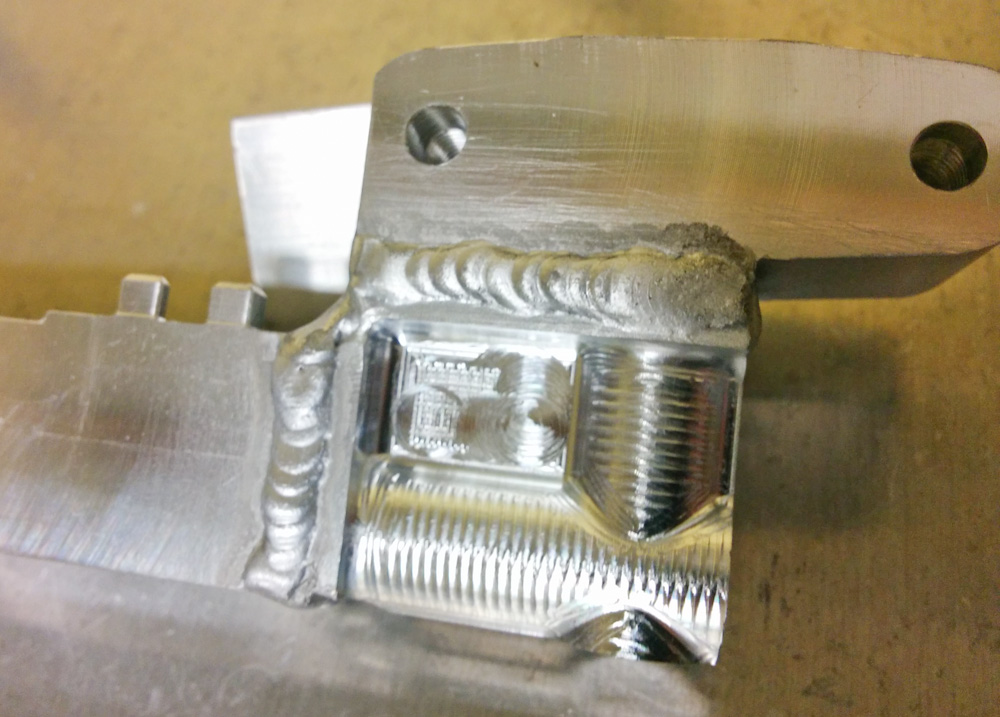
The back side was flatter, which is always easier to weld. These don’t look too bad.
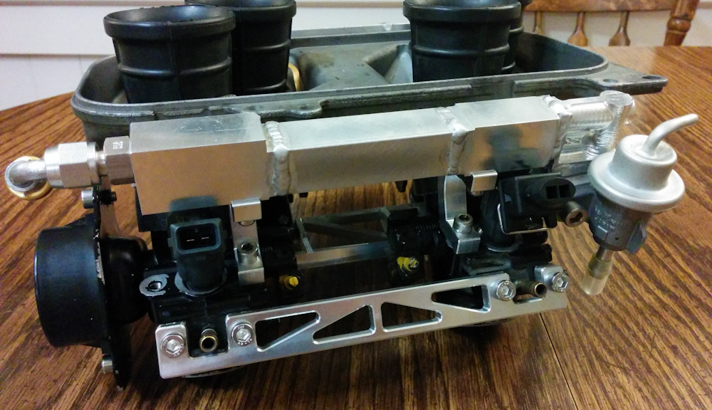
The final result, with injectors and fuel pressure regulator mounted.
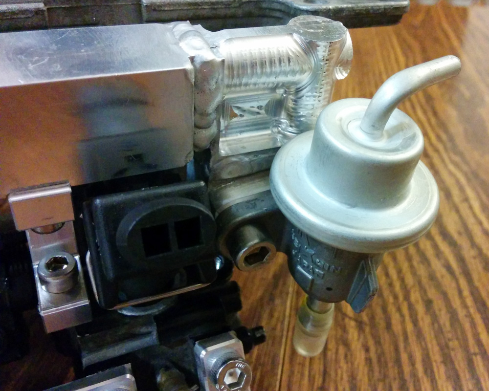
A closeup of the fuel pressure regulator and the injector for cylinder 3. It’s tight, but everything should fit.
The end result came out pretty nice. Apart from one little interference between the crankcase vent connector on the airbox (the black round thing just above the fuel rail in the rendering above) and the square tubing in the middle, it all fits. When you tighten the screws holding the rail, it’s very solidly held.
I also mounted the AN O-ring ports and made up the short piece of Aeroquip hose that connects the two fuel rails.
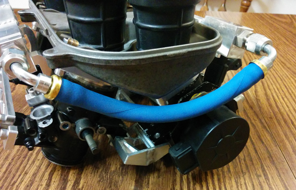
This is the short piece of hose that connects the two fuel rails to each other. It fits pretty much exactly like the CAD drawing says it would. It does touch the screw holding the throttle position sensor, but I don’t think this short piece will vibrate very much.
So that’s pretty much the fuel delivery hardware. It would now be possible to mount all the injectors, hook up the fuel pump, and test that there are no leaks. Before I do that, though, I want to clean the injectors and replace their O-rings and filters, so that’s what’s going to be next.
Pingback: Microsquirting the NC30, part #20: Leaks… – Patrik's projects
Pingback: Microsquirting the NC30, part #36: Idle tuning – Patrik's projects