As mentioned in the last post, it’s time to start working on the throttle linkage for the NC30. The requirements for this setup is that it needs to be possible to adjust the throttles of cylinders 1,3, and 4 against the cylinder 2 throttle, which is attached to the throttle cable.
Since the GPz throttle bodies I’m using originally were designed for an inline-4, they have links between each other. These won’t work for my application, not only because of the need to link the front and back cylinders, but even the two throttle bodies that line up with each other are much farther apart on the NC30 (because the gears driving the camshafts are between the cylinders.)
It so happens that the back pair of throttle bodies have their “adjustment screws” on their now-inside sides. These are mounted on the 8mm butterfly shafts with spring pins and can be removed. This makes it possible to manufacture new parts and fix them to the shafts.
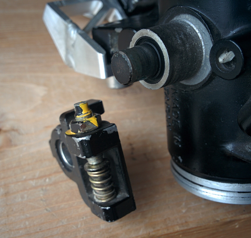
These are the existing adjustment screws on the throttle bodies, which mount to their 8mm shafts. By removing them, I can make new, longer parts and mount them on the existing shafts. The adjustment screw and the spring-loaded backer can be reused.
They also contain an M5 fine threaded adjustment screw and a spring-loaded backer that I can reuse for the new adjustment mechanisms.
The front pair unfortunately only have the mating adjustment “tab” ends of the throttle shafts facing each other. This makes it harder to mount something and ensure it is on the center axis.
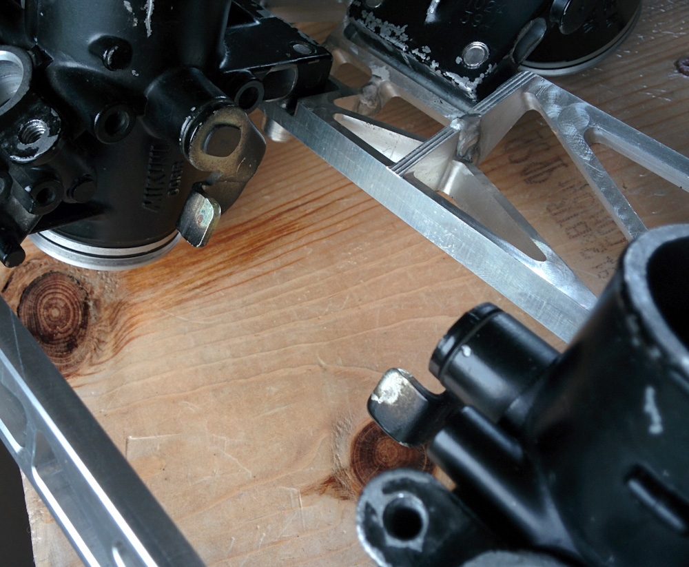
The front throttles have the “tab” ends of their shafts facing inwards. These can not be removed and are a lot harder to mount something to securely.
There are a few tricky things about making this work. The first is that, because the throttle bodies are so far apart, a simple lever mechanism like the existing one won’t work well. The long lever arm means it’s much more likely to be pushed to the side than rotate. For that reason, I’m going with a linkage that will both have a side tab and a center pin. That way the links will always be on center. The potential drawback is that if the shafts aren’t lined up well, the mechanism may bind.
The second tricky thing is that the front and rear throttle bodies are turned 180 degrees relative to each other. This means the direction of rotation of the shaft when opening the throttle is opposite, meaning the linkage has to not just transmit the rotation but also reverse its direction. In practical terms, it means the pins pushing on the linkage have to be one on the top and one on the bottom of the respective axes. See the image below.
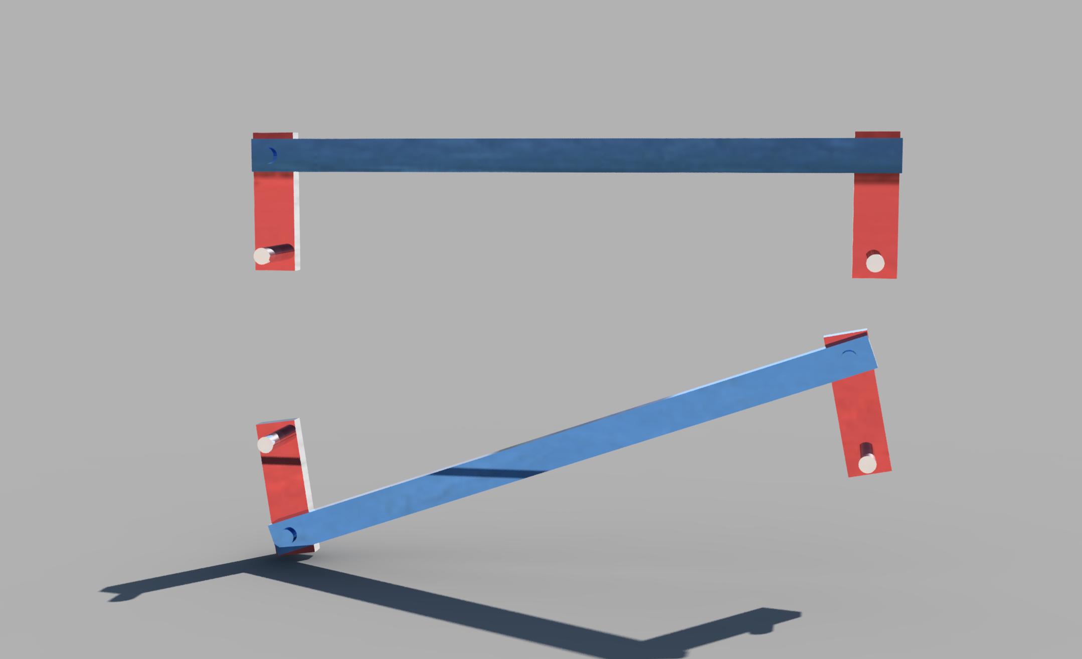
The linkage on top is not reversing and is completely linear; the two pins will rotate by the same amount. The linkage on the bottom, on the other hand, is reversing and nonlinear. Unless the two pins are infinitely far away, the rotation of two pins will not be exactly the same.
So what’s the problem? A linkage that translates rotation in the same sense can be made perfectly linear, such that a given rotation of the first axis translates to the exact same rotation of the second axis. A reversing linkage can not, it is always nonlinear to some extent. Since it is important that all four throttles open the exact same amount, at least when they are mostly closed, this is not good.
I was sufficiently puzzled by this effect that I had to pull out a notepad and do some trigonometry. The degree of nonlinearity depends on two dimensionless quantities, basically how the distance between the two axes of rotation and the length of the link relate to the length of the pins. It’s not that hard to write down the equation and solve it numerically. When you do this, you get something like this:
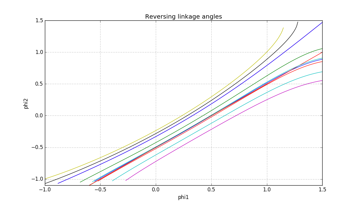
Plot of the linkage angle calculation. The x-axis is phi1, the angle of the first axis, and the y-axis phi2, the angle of the second axis, both in radians. The ideal is to have a 1:1 movement of the two axes. For a reversing linkage, this is only possible when the axes are infinitely far away. For any real linkage, phi2 will be a somewhat nonlinear replica of phi1. The cyan line in the center represents the geometry of the NC30 carburetor linkage, which is almost linear (compare to the ideal straight line in red) over most of the range. The throttle movement range is close to 90 degrees, so about 1.5 radians.
It turns out those guys at Honda apparently knew what they were doing! When I input the parameters of the NC30 carburetor linkage (which is that the distance between the axes is 6.17 times, and the length of the link is 6.00 times, the length of the pins, respectively) you get a linkage that is almost completely linear over the 90 degree motion.
Rather than reinvent the wheel, I decided to copy this geometry into my design. After a day of fiddling in Fusion 360 I now have something that clears any interference and looks like it works correctly. It will reuse the adjustment screws from the throttle bodies, use 8mm dowel pins to hold the links on the throttle shaft centerline, and 4mm dowel pins to attach the front-back link arm.
When you add all the joints in Fusion, you actually get something that looks like it’s going to work. I made a video of it moving:
Now I just have to fabricate it. It consists of 6 quite intricate parts, with reamed holes for the dowel pins that need to be lined up right, so it might be a bit of work. More on that later.
Pingback: Microsquirting the NC30, part #38: Fabricating the throttle linkage – Patrik's projects
Pingback: Microsquirting the NC30, part #40: Finishing up the throttle linkage – Patrik's projects
Hi mate. Is there any chance that you can share fusion project. I stated on my nc24 and if there is a opition I prefer to ask than start from the scratch. Plan is to print it in abs and check how is going to work as nc24 firing order is bit hard to set up and might fail before even start. Thanks
Yeah, see the comments on part #13, there are links there. Good luck!
Thanks Mate. Really appreciate 🙏. BTW you got awesome 🏍 🙂