When the last post finished up, I had the link piece for cylinder 3 left. Since it’s basically just a longer version of the one for cylinder 1, it was pretty quick to get that done.
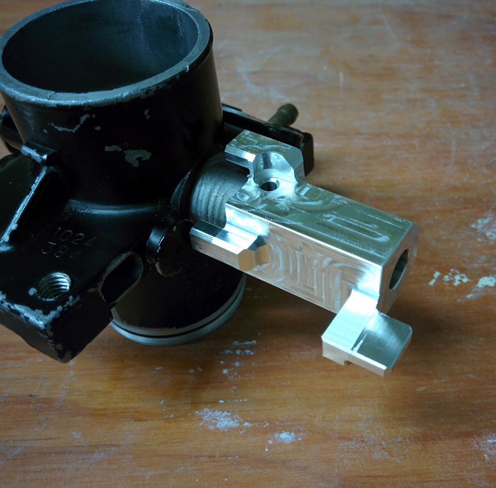
Here’s the link for cylinder #3. The spring isn’t attached at this point.
With that completed, it was time to put it all together and see if it worked.
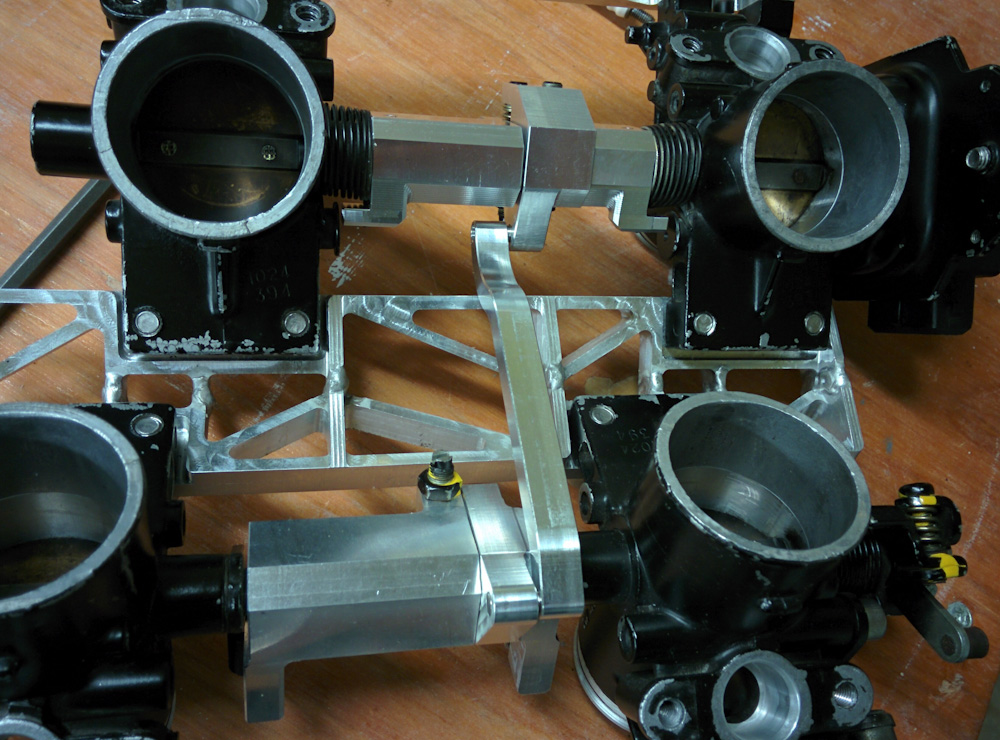
Finally, the complete throttle linkage assembly. The #1 cylinder is in the upper right, then going clockwise is #2, #4, and #3.
Testing revealed a few problems. Most seriously, the axes of the two throttle bodies were not exactly collinear. Not surprisingly, the central bracket that holds them had warped slighly when its two halves were welded together. This is a problem because the cylinder 1/3 linkages are slid onto the shafts and then linked together with a dowel pin around which the central part (the part with the adjustment screws in the top center of the picture above) can rotate. If these aren’t aligned, the shaft will bind, which it did.
To overcome this, I measured which way the bracket was warped and with a couple precisely placed squeezes in the vise managed to get the two much more aligned. I also decided that rather than having the dowel pin link both cylinder #1 and #3’s pieces, it would suffice to only let the center piece rotate around the #1 piece and let #3 be free.
The idea behind linking all of them with one long pin would be to ensure that, when the linkage moved, the throttles actually rotate rather than get pushed to the side slightly. Since the motion is transmitted between the pieces with the offset tabs, when the linkage rotates, these tabs transmit torque through an off-center force on the linkage. Unless they are securely held, this force will cause them to bend rather than rotate and not faithfully transmit the rotation angle to the next part.
However, it turns out that the parts mounted onto the shafts of the throttle bodies are very secure, so this is not necessary. Without a pin running through the entire linkage, it can accept the small misalignment better, so I used a smaller dowel pin to line up the center part with the #1 link and let #3 be free. That got rid of the binding.
Another small issue was the mounting of the links for the front (#2 and #4) cylinders. Unlike the rear ones, these throttle bodies don’t have shafts I can slide the links on (see pictures in the initial design post) but have tabs. I machined slots in the links to slide onto these tabs and fix them with a screw, but when I actually tried to mount them it turned out I didn’t have the geometry quite right. The slots weren’t deep enough and their plane wasn’t quite right to get the centerline of the linkage to line up with the centerline of the throttle bodies. This doesn’t matter so much for the motion of the front cylinders (as long as the link is parallel to the shafts it will rotate ok) but it meant that the attachment for the front-back link was not the right distance from the rotational axis. This would upset the precisely designed linkage geometry, since the front-back link has to be attached the same distance from the rotational axes at both ends.
Once diagnosed, this defect was pretty easy to fix. Since it required removing more material, I put them back in the mill and manually took off another mm from the slots.
The third issue has to do with the return springs. When I fixed the initial backward design that had the springs going in the wrong direction, I did this by mirroring the parts. The parts can be attached to the shafts in two directions, differing by 180 degrees (since they are held with the spring pin) but only one of those put the links in the correct orientation. Unfortunately, for both the rear cylinder links, this means I have the choice of the springs having barely any tension at all in the closed position or winding them up 360 degrees more which puts quite a lot of tension on them.
I first tried the less tightly would configuration, but then the springs did not have enough tension to firmly push the throttles closed. To avoid play in the front-back link, it’s important that it always be under compression. With the springs set up like this, they didn’t have enough tension when the throttle was completely closed to avoid the link going into tension. This play meant the front throttles had to open a bit before the back ones did, which was no good.
Winding the springs up another 360 degrees makes them quite tight. It solves the problem with the play, but now the throttle requires substantially more force to operate than the stock carbs do. I think it will be tiring for my weak wrists to handle, but it works well enough to give it a try. If it turns out to be a problem, I’ll remake the parts with the spring holding tab shifted 180 degrees to take half a revolution of tension out of the springs.
With all that, I now have a linkage that works! It’s going to be practically impossible to get to the adjustment screws once it’s mounted, so I’m doing my best to synchronize the four throttles before mounting it on the bike. Then it’s time to put it all together and see if it’ll run.
I’ll leave you with a live demo:
nice to meet you! My name is Watanabe and I make carbon parts such as MotoGP in Japan. I’ve always been interested in your throttle unit. This time, a friend made software for NC30 with injection, but I was worried because it was difficult to make a hard throttle unit. That reminded me of your throttle body unit. I think it’s a wonderful thing that you can operate the butterfly with one accelerator wire. I praised it when I showed my friends the video. If possible, I would like you to manufacture and sell a throttle body unit. Fuel lines and injectors can be prepared here. GPZ body is also available, but how about it? We look forward to hearing from you.