In the last post, I described the electronics used to talk to the wideband oxygen sensor controllers. What remained to do was to physically mount the sensors themselves in the exhaust pipes.
The sensors themselves are quite large, so I struggled a bit with finding a good place to mount them on the famously cramped NC30. The exhaust system is a 4-2-1 type, and the final merge collector is so far back that with one sensor it would be out on the side, basically just in front of the muffler. This location is fully visible, hard to route the wire to, and perfectly positioned for getting whacked by the rider’s left foot. Not too good.
As mentioned in the previous post, I wanted to run 2 sensors anyway. The factory carb jetting differs between the front and rear cylinders, so it seems prudent to measure their air/fuel ratios independently since they apparently require different tuning. This also had the advantage that I could locate the sensors where the exhaust pipes wrap under the bike, which is less visible and (hopefully) less susceptible to getting hit by stuff, since it’s somewhat protected by the lower fairing.
The only tricky thing is that the pipes are very nearly side by side, so there’s not much room. The sensors also must be mounted with the sensor element pointing downward by at least 10 degrees. This prevents condensation from collecting in the sensor. There was no way to fit the sensors if they were mounted 90 degrees to the pipes, but luckily there are also angled bungs. Angling them mean they take less space and you can also fine-tune the position by rotating the bungs. After some fiddling, I arrived at locations that seemed to work.
Once the locations had been determined, the next step obviously was to make holes in the pipes. This turned out to be more of a chore than expected. I knew that stainless steel work hardens, so unless your drill bits are very sharp and keep cutting, it will quickly become impossible to get through. I had new drills, but it still took me forever to make a 2mm hole, and when I stepped up to a larger drill, the edge quickly cracked. Maybe the pipes already are work hardened from manufacture?
In the end, I had to resort to the Dremel’s cutoff wheel and carbide end mill. (This end mill is amazing, it cuts anything like butter, but in the process it also produces clouds of tiny metal needles that love to embed themselves in your skin. I constantly have to remind myself to only use it on a clean work table that can be meticulously vacuumed afterwards.)
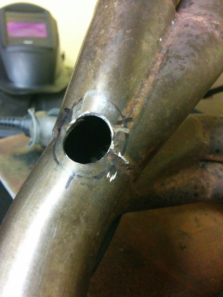
The hole is mostly done. Getting through the stainless was a chore.
To get the bungs to fit on the curved pipe, they also had to be ground into a concave shape. This was done on the bench grinder. I also had to add some material with the welder to avoid grinding into the threaded part. Once that was done, they were tack welded onto the pipe.
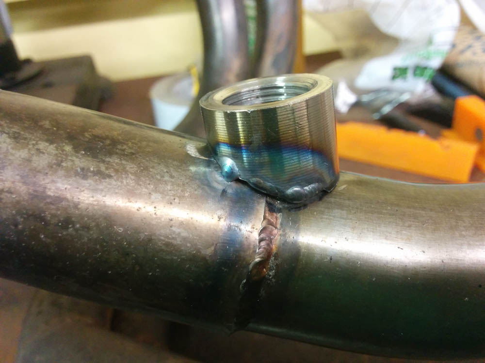
The first bung is tacked in place. I also had to weld on some material where it was initially too short.
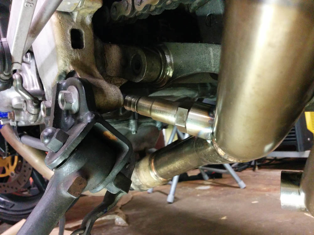
With the bungs tacked on, I put the exhaust pipe back on to check the fit. Unfortunately, the sensor to the front cylinder pair was uncomfortably close to the bracket holding the suspension linkage, so it had to be moved a bit.
Time to check the fitment. The top sensor ended up a bit too close to the suspension bracket for comfort.
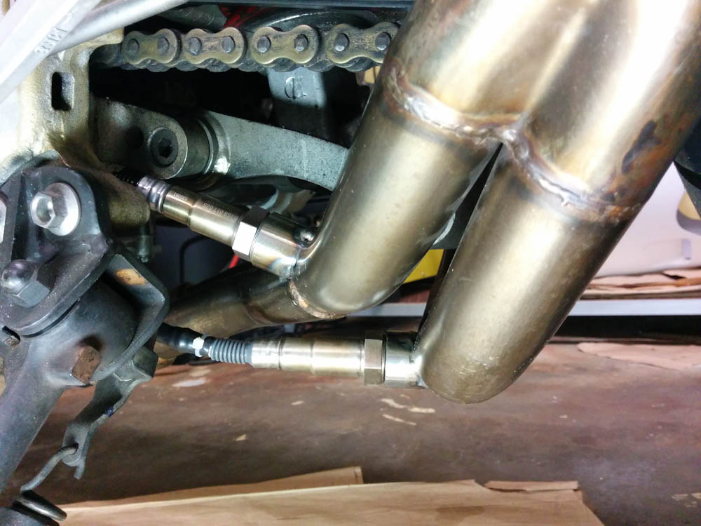
After grinding off the tack welds and moving it slightly further down, it fit much better.
After moving the bung down a bit, both sensors fit without interference. It might look like the bottom sensor doesn’t have the requisite 10-degree down angle, but I measured it with the digital level and it’s fine. (The bike also now sits on the center stand so taking it off will lower the rear end a bit more and improve the angle further.)
Then it was time for the welding. I was quite nervous about this, since I’ve never welded stainless before and an NC30 exhaust system is pretty much “unobtainium” in Hawaii. When welding stainless pipes, you also have to use a purge gas on the inside of the pipe, otherwise the weld will oxidize on the back side and lead to premature cracking. To do this, you cover the ends of the pipe and route another Argon bottle into it.
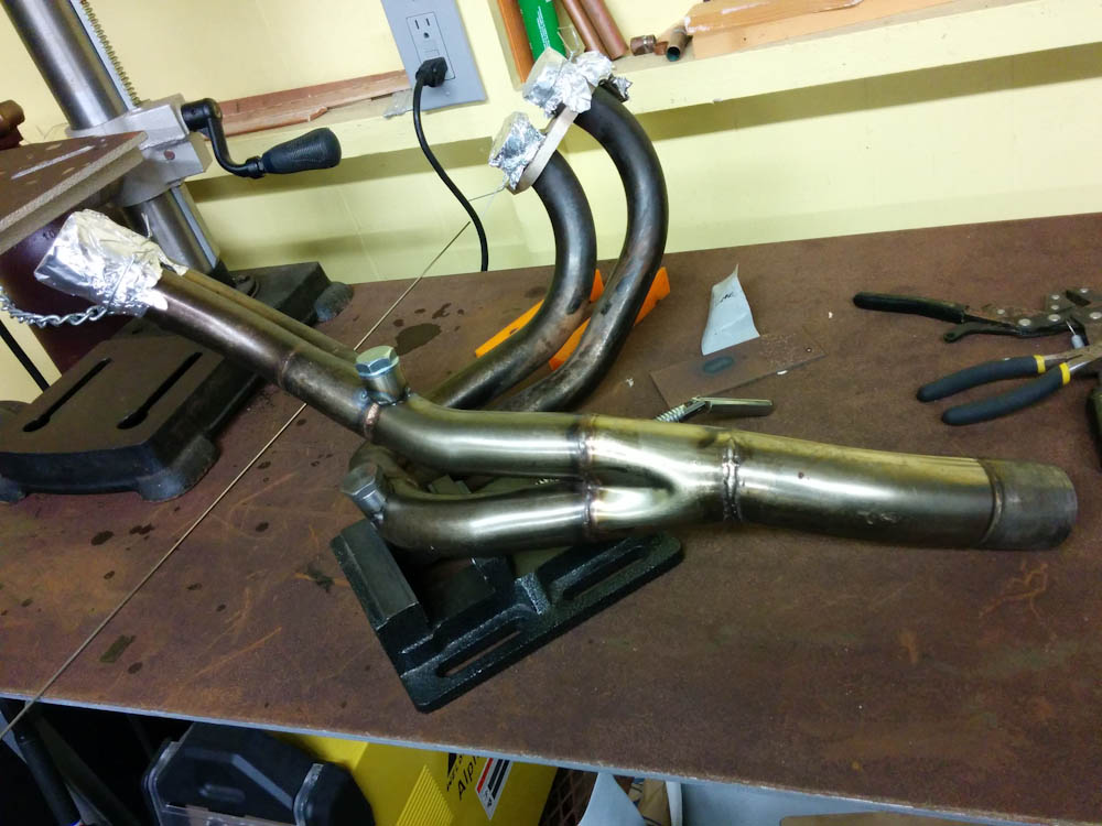
The exhaust system is ready for welding. The aluminum foil is to keep the purge gas contained. The Argon hose was mounted at the muffler end and that side taped off. A couple small holes in the aluminum foil give the existing air a place to exit.
I’m happy to report the welding worked fine. It was a bit awkward to access the side of the lower bung that faces the other pipe, but the weld wetted out easily and I didn’t burn any holes in the pipe! I think it looks pretty good for a first attempt!
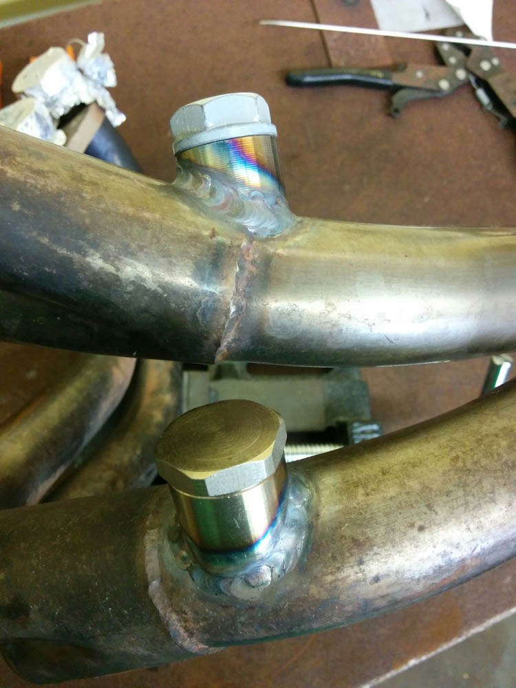
The welds are done. Not too bad for the first time welding stainless!
I’ve been anxious about this welding step since I first started thinking about the project, so I’m happy that’s done. Now I can proceed with routing the wires to the sensors and then it’s finally time to do all the wiring between the fuse box, the Microsquirt, and the electronics box.
Duktigt!
Very nice work, can’t wait to see your solution to the throttlebody.
Pingback: Microsquirting the NC30, part #4: Wiring up the fusebox | Patrik's projects
Pingback: Microsquirting the NC30, part #34: Finishing up the exhaust – Patrik's projects