As described in the first post in this series, I’m working on converting the NC30 to fuel injection. That post was 2 months ago, since then I’ve mostly been working on a box of electronics that aren’t exactly required but that I think will make things a lot better.
When designing the whole Microsquirt system, there are a couple of loose ends that need to get tied up:
- Pressure sensors for barometric and manifold pressure need wiring up, with dedicated analog lines. You can use automotive sensors for this, but they’re a lot more expensive than the ones you can get from Mouser.
- For tuning, you need to connect the ECU to a computer. Normally this is done over RS232, but I wasn’t psyched about having a serial connector somewhere on the bike exposed to the weather. Instead, you can use a Bluetooth serial bridge and connect to the bluetooth on the laptop. However, you need to put the Bluetooth modem in some protected location.
- Finally, you need to hook up wideband oxygen sensors. Most consumer-grade ones output an analog voltage, which means you have to be very careful about signal interference. However, there’s a DIY one you can buy as a kit from 14point7 that can also be read digitally over I2C. You can then send this data to the Microsquirt over the CAN-bus connection, eliminating any analog part from this very important signal. This seemed like an obvious use for an Arduino…
At first, I meant to accomplish this in an as simple as possible way, using a breadboard and breakout boards and DIP chips. However, it quickly became clear that this would not be much easier and would be really clunky. Instead, I decided to design a small breakout board with surface-mount Atmega microcontroller and the CAN-bus controller/transceiver. I’ve never used any of the on-demand circuit board businesses, but it turns out that small boards are really cheap. I used OshPark, and the small double-sided board ended up costing $6 for 3, including shipping! And they’re purple!
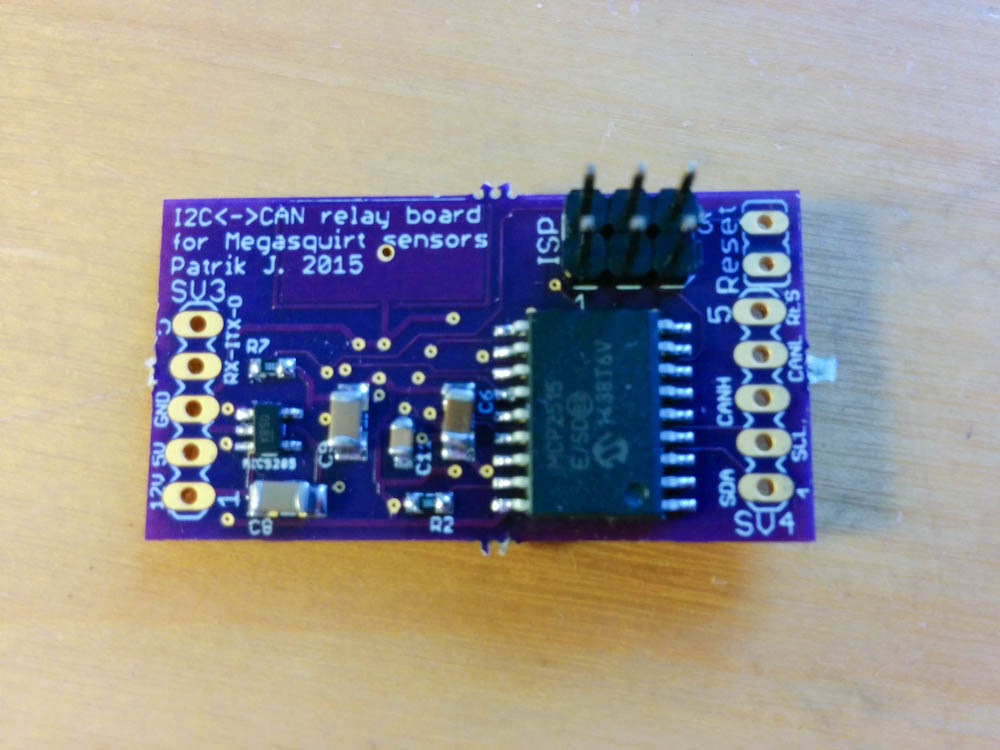
The front side of thee OshPark board after soldering on the SMT components. The large chip is the CAN-bus controller.
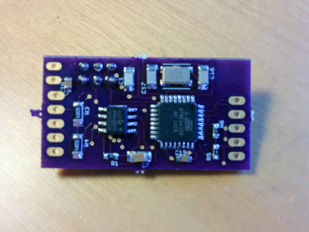
The back side of the relay board. The large chip is the Atmega 328 and the small one the CAN-bus transceiver.
I had already tested this with an Arduino and DIP versions of the CAN-bus components, so I knew I could send data to the Microsquirt and have it show up as fuel/air ratios.
With the complicated circuiry out of the way, I just needed a simple board to mount the pressure sensors, the Bluetooth modem, and connect to the wideband controllers. This was sufficiently simple that I decided to make a single-sided board myself using toner transfer.
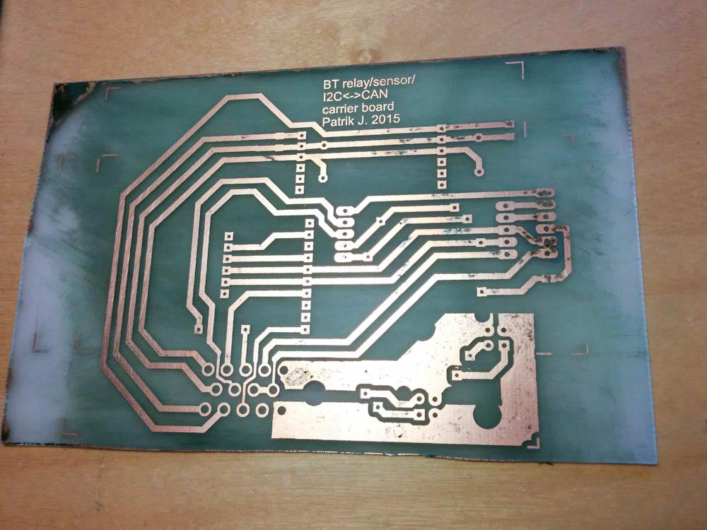
Here’s the single-sided carrier board after etching. Not perfect, by any means, but it’ll work. The super-wide traces in the lower right is for the power supply to the wideband oxygen sensor controllers. Since the sensor has a heater, they actually use up to 5A per sensor.
I haven’t done any etching since the wine refrigerator project back at the beginning of this blog, so it took a while to remember all the subtleties. And while this worked fine, when you take into account time spent doing transfers, etching, drilling, etc, it’s not at all clear that it’s cost effective compared to ordering from OshPark. This board has a lot of area, so it would have been about $30, but it also took me quite a few hours to do by hand.
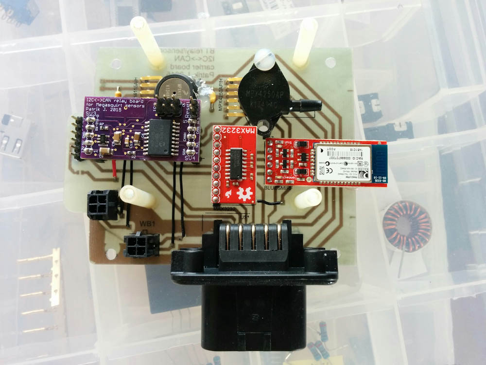
This is the fully assembled carrier board. The pressure sensors are at the top (the MAP sensor is the one with a barb, the barometric pressure one obviously doesn’t need one.) The red boards are breakout boards from Sparkfun with the Bluetooth modem and RS232 level converter. The two MicroFit connectors in the lower left are the power and I2C connections to the wideband sensors. The large connector is the external Ampseal connector.
The plan was to stack this board and the two wideband controller boards and mount them in a weatherproof enclosure. The stacking worked out quite well and everything fit perfectly into the Hammond enclosure.
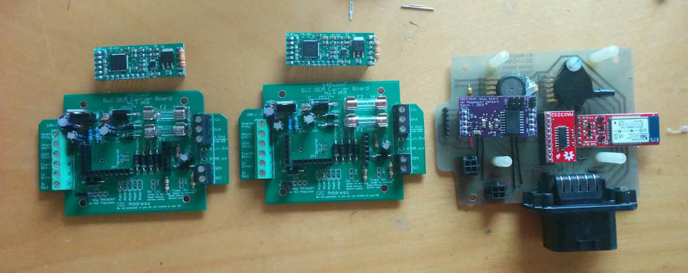
The two Sigma Lambda OEM wideband oxygen sensor controller boards from 14point7.com along with my board, ready for stacking.
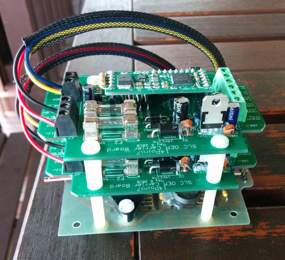
This is the assembled board stack, ready to go in the box.
Getting the boards into the enclosure turned out to be a bit more work than expected. The problem is that the enclosure is quite deep, and the Ampseal connector quite large.
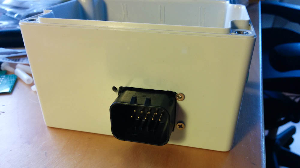
The Ampseal connector has a seal on the inside that will seal against the inside wall of the enclouser, so the hole in can’t be too large. This means it’s tricky to get the board in.
After careful filing I managed to make a hole large enough that the connector can be jammed through, with only a little flexing of the circuit board, while keeping it smaller than the seal on the flange. As you can see in the picture above, I failed a bit on locating the screw holes, but they are all on the “external” side of the seal so it’s only a cosmetic matter.
In the end, the enclosure is quite large, so there’s really only one place on the bike where it fits: in the tail along with the other electronics. There’s not really any extra space, but it works.
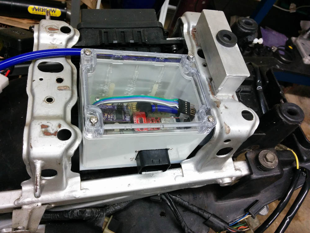
This shows how the enclosure fits perfectly between the two metal bars in the tail. The blue silicone hose is the MAP sensor connection. The connector fits outward because it would be really tight against the back of the fuse box on the other side if it fit the other way. The tail fairing is plenty wide there to accommodate the connector.
So that’s where it’s at right now. I’m currently in the process of welding bungs for the oxygen sensors onto the exhaust pipes, once that’s done and I know how long those wires need to be, I can mount this box permanently and start the job of wiring everything up.
You definitely have the skills necessary to make this project happen. I will thoroughly enjoy watching as you work.
Greg
Pingback: Microsquirting the NC30, part #3: Mounting the Oxygen sensors | Patrik's projects
Pingback: Microsquirting the NC30, part #3: Mounting the Oxygen sensors – Patrik's projects